1
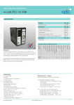
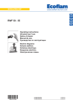
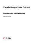
7 Compact universal controllers 866 RWF50... The RWF50 is used mainly for controlling the temperature or pressure in oil- or gas-fired heating plants. If the relevant parameters are set, the RWF50 can be switched to cooling mode and then controls in reverse operation. The RWF50 and this Data Sheet are intended for use by OEMs which integrate the controllers in their products! Use The RWF50 is used either as a 3-position controller without angular positioning feedback or a continuous controller with analog output depending on the version. An external switch can be used to change to a 2-position controller for controlling 2-stage burners. The integrated thermostat function switches the burner on and off. LED symbols on the front indicate the following operating states: Burner release Control pulses OPEN or CLOSED for driving the burner’s air damper when using a modulating burner control, or stage I / stage II when using 2-stage burner control 2-stage operation During operation, the digital displays above the keys shows the setpoint (green), the actual value (red) and – when making parameter settings – the relevant parameters. CC1N7866en 25.07.2014 Building Technologies Division Infrastructure & Cities Sector Supplementary documentation User Manual RWF50 ............................................................................................. U7866 Environmental Declaration RWF50 ........................................................................ E7866 Warning notes To avoid injury to persons, damage to property or the environment, the following warning notes must be observed! Do not open, interfere with or modify the unit! All activities (mounting, installation and service work, etc.) must be performed by qualified staff Before making any wiring changes in the connection area, completely isolate the plant from mains supply (all-polar disconnection). Ensure that the plant cannot be inadvertently switched on again and that it is indeed dead. If not observed, there is a risk of electric shock hazard Ensure protection against electric shock hazard by providing adequate protection for the connection terminals When selecting the cable material, during installation and when creating the electrical connections, observe the regulations of VDE 0100 Erection of power installations with rated voltages below AC 1000 V and the relevant national regulations Disconnect the device from the mains supply if there is a risk of touching live parts while work is carried out Each time work has been carried out (mounting, installation, service work, etc.), check to ensure that wiring is in an orderly state Fall or shock can adversely affect the safety functions. Such units must not be put into operation, even if they do not exhibit any damage. Caution! The safety, warning and technical notes given in the User Manual on the RWF50 (U7866) apply fully to the present document also! Mounting notes Ensure that the relevant national safety regulations are complied with. Standards and certificates Conformity to EEC directives - Electromagnetic compatibility EMC (immunity) - Low-voltage directive, to DIN EN 60730-1 ISO 9001: 2008 Cert. 00739 2004/108/EC 2006/95/EC ISO 14001: 2004 Cert. 38233 2/11 Building Technologies Division Infrastructure & Cities Sector CC1N7866en 25.07.2014 Service notes For service purposes, the controller can be removed from its housing. This can however lead to damage of the housing The electrical connections are made via the fixing terminals on the rear of the housing Disposal notes The unit contains electrical and electronic components and must not be disposed of together with domestic waste. Local and currently valid legislation must be observed. Type summary Compact universal controller Basic version 3-position output Housing Fixing frame and seal User Manual Single pack RWF50.20A9 Compact universal controller Basic version Analog output Housing Fixing frame and seal User Manual Single pack RWF50.30A9 Packaging variants (30 pieces, without User Manual) RWF50.21A9 RWF50.31A9 PC software ACS411 3/11 Building Technologies Division Infrastructure & Cities Sector CC1N7866en 25.07.2014 Technical Data Inputs Resistance thermometers Type Measuring range Measuring accuracy a Pt100; DIN EN 60751 -200...850 °C (-328...1562 °F) -200...850 °C (-328...1562 °F) -50...+160 °C (-58...320 °F) 0.1% Impact of ambient temperature 50 ppm/K 0.1% 50 ppm/K 0.1% 50 ppm/K 0.25% 50 ppm/K Pt1000; DIN EN 60751 LG-Ni1000 0...135 a Accuracies relate to the maximum measuring range. Input signals Line resistance Line balancing Max. 30 per line with 3-wire circuit Not required with 3-wire circuits. With 2-wire circuits, line balancing can be performed by making an actual value correction Measuring range Measuring accuracy a 0.1% Impact of ambient temperature 100 ppm/K 0.2% 200 ppm/K 0.1% 100 ppm/K Voltage DC 0...10 V Input resistance RE >2 M Voltage DC 0(1)...5 V Input resistance RE >2 M Current 0(4)...20 mA Voltage drop 2 V a Accuracies relate to the maximum measuring range. Binary input D1 Potentialfree contact for the following functions, depending on the configuration: No function Setpoint readjustment Setpoint changeover Operating mode changeover Monitoring the measuring circuit In the event of error, the outputs assume defined states (configurable). Measuring transducer Resistance thermometer Voltage 1...5 V 0...5 V, 0...10 V Current 4...20 mA 0...20 mA Measured value crossed limit Sensor/line has short-circuit Sensor/line interrupted ● ● ● ● (●) ● (●) ● --● --- ● --● --- ● = detected (●) = detected only if measuring range is exceeded - = not detected 4/11 Building Technologies Division Infrastructure & Cities Sector CC1N7866en 25.07.2014 Technical Data (cont'd) Controller outputs OutP Relay K1 (NO) 1P, 1N (burner release) Contact rating Contact life Contact protection Power supply for transducer G+, G- Max. 1 A at AC 250 V at cosφ >0.6 100,000 switching cycles at high-fire Varistor DC 24 V 10%/max. 25 mA short-circuitproof The following relay data are those specified by the supplier. Only RWF50.2 Relay K2, KQ (controlling element OPEN) Contact rating Contact life Contact protection Relay K3, KQ (controlling element CLOSE) Contact rating Contact life Contact protection Max. 1 A at AC 250 V and cosφ >0.6 100,000 switching cycles at high-fire RC combination Max. 1 A at AC 250 V at cosφ >0.6 100,000 switching cycles at high-fire RC unit Relay data are those specified by the supplier. Only RWF50.3 Controller Electrical data Analog output A+, AVoltage Load resistance Accuracy Current Load resistance Accuracy DC 0...10 V short-circuit-proof RLast ≥500 0.25%, 50 ppm/K 0...20 mA/4...20 mA RLast 500 0.25%, 50 ppm/K Type of controller - RWF50.2 - RWF50.3 Controller structure Sampling time Modulating controller Continuous controller P/PI/PD/PID 250 ms Power supply (switching network section) Electrical safety Power consumption Data backup Electrical connection - Cross-sectional area - Stranded wire with With UL applications Tightening torque Electromagnetic compatibility Emitted interference Immunity AC 110...240 V +10/-15% 48...63 Hz To DIN EN 60730, part 1 Overvoltage category II Degree of contamination 2 Max. 16 VA EEPROM At the rear via screw terminals 0.25...1.5 mm² fine-wired - Ferrules to DIN 46228 - Pin-type cable socket to DIN 46231 - Crimp-type cable socket in fork-form for M3 thread (dimensions to DIN 46237) Use of the cable lug or ferrules to UL486A-B (UL listed or recognized) 0.5 Nm DIN EN 61326-1 Class B Meeting industrial requirements 5/11 Building Technologies Division Infrastructure & Cities Sector CC1N7866en 25.07.2014 Technical Data (cont'd) Housing Type of housing Weight - RWF50.2 - RWF50.3 Made of Makrolon for control panel mounting to DIN IEC 61554 (use in indoor) Light-grey RAL7035 92 mm Optional To DIN EN 60529 Front side IP66 Rear IP20 (Fully equipped) Approx. 170 g Approx. 168 g Storage Climatic conditions Mechanical conditions Temperature range Humidity Transport Climatic conditions Mechanical conditions Temperature range Humidity Operation Climatic conditions Mechanical conditions Temperature range Humidity Installation altitude DIN IEC 60721-3-1 Class 1K3 Class 1M2 -40...70 °C <95% r.h. DIN IEC 60721-3-2 Class 2K2 Class 2M2 -40...70 °C <95% r.h. DIN IEC 60721-3-3 Class 3K3 Class 3M3 -20...50 °C <95% r.h. Max. 2,000 m above sea level Color Mounting depth Mounting position Degree of protection Environmental conditions Attention! Condensation, formation of ice and ingress of water are not permitted! Segment display Height of numerals - Upper display - Lower display Color - Upper display - Lower display Digits Range of display 10 mm 7 mm Red Green 4 (including 0, 1 or 2 decimal places, configurable) -1999...9999 6/11 Building Technologies Division Infrastructure & Cities Sector CC1N7866en 25.07.2014 Function The following functions are included in the RWF50: Digital PID controller with a 3-position or analog output of the calculated output level The controller can be switched to a 2-position controller for controlling 2-stage burners Automatic thermostat (or pressure controller) function in low-fire operation Minimum limiter and maximum limiter for the boiler temperature or boiler pressure Manual operating mode Self-setting function Parameterization and visualization via USB interface and PC software ACS411 Ramp functions (cold start/thermal shock protection) Heating/cooling Block structure Only RWF50.2: Air damper control Only RWF50.3: 7/11 Building Technologies Division Infrastructure & Cities Sector CC1N7866en 25.07.2014 Function of the controller when used for burner control Low-fire operation Low-fire operation means that only small amounts of energy are drawn from the boiler. With the relay 1 burner release, the 2-position controller controls the set setpoint by switching the burner on and off like a thermostat. An adjustable switching differential ensures that the burner’s switching frequency can be selected to help protect the material. High-fire operation High-fire operation means that large amounts of energy are drawn from the boiler with the burner running continuously. The RWF50 controls the required output using the 3position or analog output. Operation The RWF50 is operated and programmed with 4 buttons on the front of the unit. During operation and programming, the 7-segment displays show the parameter value and parameter name. Analog input To acquire the actual value, a number of sensors can be connected to the RWF50. Measuring range Resistance thermometer Pt100 -200...+850°C (-328...+1562 °F) in 2-wire or Pt1000 -200...+850°C (-328...+1562 °F) 3-wire technology LG-Ni1000 -50...+160°C (-58...+320 °F) Linearized 0...135 Ohm scalable -1999...+9999 standard signals 0...20 mA scalable -1999...+9999 4...20 mA scalable -1999...+9999 DC 0...10 V scalable -1999...+9999 DC 0...5 V scalable -1999...+9999 DC 1...5 V scalable -1999...+9999 The power provided for the measuring transducers is DC 24 V ±10% / max. 25 mA. 8/11 Building Technologies Division Infrastructure & Cities Sector CC1N7866en 25.07.2014 Connection diagram 3-position output 7866a12e/0912 RWF50.2 Rx Ux P Ix – Binary input S Burner release + Analog input + Rx AC 110... 240 V +10%/-15% 48...63 Hz DC 24 V ±10% Max. 25 mA Measuring transducer supply Legend The RWF50 contains these components Ix Current input K2 Relay: Controlling element OPEN K3 Relay: Controlling element CLOSED KQ common pole 1N Relay K1: NO-contact S NO-contact P Pole 1P Relay K1: Pole Rx Resistance Ux Power supply input 9/11 Building Technologies Division Infrastructure & Cities Sector CC1N7866en 25.07.2014 Connection diagram (cont'd) Rx + Ux P Ix – S Binary input Analog input + Rx Burner release DC 0(4)...20 mA DC 0...10 V 7866a13e/0912 Analog output RWF50.3 AC 110... 240 V +10%/-15% 48...63 Hz DC 24 V ±10% Max. 25 mA Measuring transducer supply Legend A+ AIx The RWF50 contains these components Analog output (+) Analog output (-) Current input 1N Relay K1: NO-contact S NO-contact P Pole Rx Resistance 1P Relay K1: Pole Ux Power supply input 10/11 Building Technologies Division Infrastructure & Cities Sector CC1N7866en 25.07.2014 Dimensions 50 Dimensions in mm 104 7866m02/0714 2014 Siemens AG Infrastructure & Cities Sector Building Technologies Division Subject to change! Building Technologies Division Infrastructure & Cities Sector 11/11 CC1N7866en 25.07.2014