1
ITALFARAD S.p .A. via IV novembre n.1 Minerbio (BO) It aly
I
Istruzioni per l’uso
I
GB
Operating instructions
GB
ITALFARAD S.p .A. via IV novembre n.1 Minerbio (BO) It aly
ITALFARAD S.p .A. via IV novembre n.1 Minerbio (BO) It aly
2
ITALFARAD S.p .A. via IV novembre n.1 Minerbio (BO) It aly
Italiano
4
English
11
3
I
ITALFARAD S.p .A. via IV novembre n.1 Minerbio (BO) It aly
Italiano
Un solo modulo per la misura trifase e la protezione dei quadri elettrici
5
Visualizzazioni e tasti
5
Modalità di funzionamento
6
Messa in servizio e predisposizioni dei parametri di funzionamento
8
Caratteristiche tecniche
9
4
I
ITALFARAD S.p .A. via IV novembre n.1 Minerbio (BO) It aly
SPC2
STRUMENTO DI CONTROLLO E PROTEZIONE TRIFASE
Un solo modulo per la misura trifase e la protezione dei quadri elettrici
Il dispositivo SPC2 è finalizzato alla protezione e controllo dei quadri e degli impianti
elettrici, in particolare dei sistemi di rifasamento automatici e di filtro, attraverso il
monitoraggio continuo delle tensioni di linea,
delle correnti capacitive (ampiezza e contenuto armonico) e della temperatura di impianto.
Il valore di tensione di ogni fase viene confrontato con un valore di soglia impostato, generando un allarme al perdurare del supero.
Il segnale di corrente di ogni fase viene elaborato per calcolarne l’ampiezza totale ed il
contenuto armonico totale THD (Total Harmonic Distortion): al superamento di una soglia di
corto circuito o di distorsione massima programmata viene generata una segnalazione di
allarme.
Il valore di temperatura viene monitorato per
comandare l’inserzione di dispositivi di raffreddamento al superamento di una soglia di
preallarme e generare un allarme qualora
sia superata la temperatura massima impostata.
Tutte le misure e le segnalazioni effettuate dal dispositivo sono visualizzate tramite display sul
pannello frontale. La programmazione dei parametri di funzionamento è realizzata tramite 4 tasti
funzionali.
Le ridotte dimensioni (DIN 96x96 mm) ed il costo contenuto rendono il dispositivo idoneo
all’impiego in tutti gli impianti industriali e civili.
Visualizzazioni e tasti
LED MISURE
V, I, THD%,
Iharm, Hz, °T
Indicano la misura correntemente visualizzata sul display a 3 digit: tensione
concatenata, corrente di fase, distorsione armonica totale di corrente di
fase, corrente armonica di fase, frequenza di rete, temperatura del quadro.
L1, L2, L3
Indicano la fase cui si riferisce la misura correntemente visualizzata. Per le
tensioni, l’accensione contemporanea di due led indica le fasi cui si riferisce
la tensione concatenata (es. L1-L2 indica la tensione V12).
x 1000
Moltiplicatore x 1000 della misura correntemente visualizzata.
LED DI STATO
FAN
Indica il supero della prima soglia di temperatura e la attivazione del relè di
comando dispositivo di raffreddamento.
MANUAL
RESET
Acceso: è selezionata la modalità manuale di reset allarmi.
Spento: è selezionata la modalità automatica di reset allarmi, allo scomparire della condizione di allarme (escluso allarme di sovratemperatura).
ALARM
Lampeggia unitamente alla grandezza in allarme per indicare una condizione di allarme raggiunta da una o più grandezze.
5
I
ITALFARAD S.p .A. via IV novembre n.1 Minerbio (BO) It aly
TASTI
RESET/PHASE
+/MAX
-/MIN
SCROLL
In visualizzazione seleziona la fase di misura da visualizzare a display se
premuto per breve tempo oppure azzera gli allarmi presenti ed i valori min/
max. se premuto per 5 secondi.
In programmazione forza il valore di default del parametro corrente.
Se premuto durante l'accensione del dispositivo, forza la programmazione di
default.
In visualizzazione mostra il valore massimo della misura correntemente visualizzata.
In programmazione Incrementa il valore del parametro.
In visualizzazione mostra il valore minimo della misura correntemente visualizzata.
In programmazione decrementa il valore del parametro.
In visualizzazione seleziona la misura da visualizzare sul display.
In programmazione seleziona il parametro da programmare.
TASTI SPECIALI (due tasti premuti insieme)
SCROLL insie- Se premuti per 10 secondi circa, attivano il modo programmazione parametri.
me a +/MAX
SCROLL insie- Se premuti in modo visualizzazione, memorizzano la misura corrente come misura di default sul display ad ogni accensione.
me a -/MIN
+/MAX insieme Se premuti in modo visualizzazione, attivano (per le grandezze trifase) la
scansione ciclica delle fasi sul display.
a -/MIN
RESET/PHASE
Se premuti all’accensione invertono la modalità di collegamento
insieme a
(monofase o trifase)
SCROLL
RESET/PHASE
Attivano manualmente il rele di comando del dispositivo di raffreddamento.
insieme a +/MAX
RESET/PHASE Disattivano manualmente il rele di comando del dispositivo di raffreddainsieme a -/MIN mento.
Modalità di funzionamento
Protezione di
tensione
Il valore di ogni tensione fase-fase, misurato in true RMS, viene confrontato con
il valore di soglia impostato. Se il supero oltre la soglia in presenza di corrente
perdura per un tempo superiore a 30 min. viene attivata la segnalazione visiva
(lampeggio led: tensione, fase e alarm) e comandato il relè di allarme.
Protezione di
corrente
Il valore di ogni corrente di fase, misurato in true RMS, viene confrontato con il valore di riferimento posto a 120% del valore nominale (corrente primaria impostata). Se
il supero oltre la soglia perdura per oltre 3 secondi, viene attivata la segnalazione
visiva (lampeggio led: corrente, fase e alarm) e comandato il relè di allarme.
Protezione di
THD
Protezione di
temperatura
Il segnale di ogni corrente di fase viene elaborato per estrarne il valore di distorsione
totale. Tale valore viene confrontato con il valore di soglia impostato relativo allo
stato operativo attuale (soglia per alta corrente o soglia per bassa corrente): se il
supero oltre la soglia perdura per un tempo superiore a quello impostato, viene
attivata la segnalazione visiva (lampeggio led: THD, fase e alarm) e comandato il
relè di allarme.
Il valore di temperatura viene confrontato con la soglia di temperatura impostata: se
il supero oltre la soglia perdura per un tempo superiore a 10 secondi, viene acceso il
led FAN e comandato il relè di azionamento dispositivo di raffreddamento. Se la
temperatura supera la somma del valore di soglia e del valore di delta temperatura,
viene attivata la segnalazione visiva (lampeggio led: °T e alarm) e comandato il relè
di allarme. Tale allarme è ripristinabile solo manualmente.
In condizione di allarme di temperatura, viene aperto il contatto del relè di
azionamento dispositivo di raffreddamento.
6
I
ITALFARAD S.p .A. via IV novembre n.1 Minerbio (BO) It aly
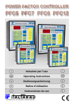
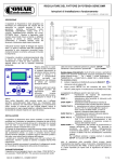
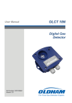
I tempi di intervento di tutte le protezioni effettuate dall'apparato sono di tipo
integrale, tengono cioè conto dei tempi precedenti di supero delle soglie di allarme, come indicato in figura:
Tempi di
intervento
L'azzeramento del temporizzatore integrale degli allarmi si ottiene manualmente
premendo il tasto RESET/PHASE (per 5 secondi circa) o automaticamente dopo
che è trascorso un tempo pari al tempo di intervento senza che la grandezza
abbia superato la soglia limite.
RESET Allarmi
Al verificarsi di un evento di allarme, l'apparato segnala la condizione attivando il relè di allarme e visualizzando sul display la grandezza che lo ha generato ed i corrispondenti led di fase e misura, il tutto
con dinamica lampeggiante. Fino a che permane la condizione di
allarme il dispositivo si porta, dopo 10 sec. di inattività, nella visualizzazione della misura che lo ha generato.
Sono possibili due modalità di ripristino degli allarmi: manuale premendo il tasto RESET/PHASE per circa 5 secondi, oppure automatica allo scomparire della condizione di allarme. In caso di ripristino
automatico, se si verificano più di 3 allarmi entro un'ora viene comunque richiesto un reset manuale, per segnalare una condizione di
probabile guasto nel sistema sotto controllo.
L'allarme da sovratemperatura richiede sempre il ripristino manuale.
Selezione misura di
default sul display
Per impostare la misura di default visualizzata all'accensione sul
display, selezionare la misura desiderata sul display e premere il
tasto SCROLL insieme al tasto -/MIN.
Scansione ciclica
delle misure sul
display
In modalità trifase la scansione ciclica (ogni 3 secondi) della fase
della misura visualizzata sul display viene avviata mediante la pressione del tasto +/MAX insieme al tasto -/MIN ed interrotta alla pressione del primo tasto.
Test dispositivo di
raffreddamento
E' possibile comandare manualmente il relè di attivazione dispositivo
di raffreddamento, premendo insieme i tasti RESET/PHASE e +/
MAX per attivarlo e RESET/PHASE e -/MIN per disattivarlo. Il comando manuale è disabilitato in condizione di allarme o di raffreddamento.
7
I
ITALFARAD S.p .A. via IV novembre n.1 Minerbio (BO) It aly
Messa in servizio e predisposizioni dei parametri di funzionamento
Connettere l'apparato all'impianto secondo lo schema di connessione ed alimentarlo: il dispositivo
si porta automaticamente in modo misura visualizzando la misura di default.
Per accedere alle funzioni di programmazione dei parametri di funzionamento occorre premere
contemporaneamente il tasto SCROLL ed il tasto +/MAX per circa 10 secondi: una volta entrato in
modo programmazione, indica con i led i parametri da programmare, facendo lampeggiare sul
display il loro valore corrente. I valori di soglia impostati sono unici e validi per le tre fasi.
La corrispondenza tra parametri da programmare e led è la seguente:
Parametro
Led
Soglia di tensione
Led V
Corrente primaria CT
Led I
Soglia THD% per alta corrente
Led THD%
Delay THD
Led THD% insieme a Led Iharm
Soglia T°
Led T°
Delta T°
Led T° insieme a Led Iharm
Tipo di reset (Automatico/Manuale)
Rapporto TV
Tutti i led spenti
Soglia di corrente Quad. Low I – Quad. High I
Led I lampeggiante
Soglia THD% per bassa corrente
Led THD% lampeggiante
Parametro di taratura della Temperatura
Led T° lampeggiante
Led V lampeggiante
Utilizzare i tasti +/MAX e -/MIN per modificare il valore del parametro visualizzato ed il tasto
SCROLL per posizionarsi sul parametro successivo. Premendo il tasto RESET/PHASE per 5 secondi si forza il valore di default del parametro corrente.
Per uscire dalla modalità programmazione, attendere circa 10 secondi senza premere alcun tasto:
al termine, l'apparato torna automaticamente in modo misura.
La tabella seguente indica i valori di programmazione di ogni parametro.
Simbolo
Grandezza
V
Soglia di tensione
CT
Corrente primaria trasformatore di corrente
THD% HIGH Soglia distorsione totale THD per alte correnti
DELAY
°T
° T
AUT/MAN
VT
I% H-L
THD% LOW
OFFTEMP
Tempo intervento allarme THD
Valori programmabili
Default
da 360 a 480 Volt
da 5 a 10k Amp
da 5% a 250%
440 V
600 A
35%
120
sec.
da 5 a 900 sec.
Soglia di temperatura inserzione dispositivo
da 25 °C a 50 °C
di raffreddamento
Soglia di allarme di sovra-temperatura rispetto alla
da 0 °C a 30 °C
soglia di inserzione dispositivo di raffreddamento
AU1 = Automatico al rientro da supero (Mod.1)
AU2 = Automatico al rienTipo di reset allarmi
tro da supero (Mod.2)
MAn = Manuale con il
tasto RESET/PHASE
Rapporto trasformatore di tensione (/100V)
{1; 2.2; 3.8; 4.4; 5; 6; 8; 10}
Soglia di corrente (in % rispetto al valore
Da 0% a 100%
nominale) tra stato di Low I e High I.
Soglia distorsione totale THD per basse correnti
da 5% a 250%
35 °C
Parametro di taratura della temperatura
0 °C
8
da -30 °C a 30 °C
25 °C
AU1
1
10%
70%
I
ITALFARAD S.p .A. via IV novembre n.1 Minerbio (BO) It aly
Caratteristiche tecniche
Alimentazione
Potenza assorbita
Dimensioni
Peso
Ingressi di tensione
Impedenza di ingresso
Ingressi di corrente
Sovraccarico di corrente
Assorbimento circuiti di corrente
Precisione misura tensione
Precisione misura corrente
Risoluzione misura corrente
Precisione misura THD corrente
Precisione misura temperatura
Precisione misura di frequenza
Precisione tempi
Contatti relè dispositivo raffreddamento
Contatti relè allarme
Collegamenti
Linea seriale RS232
Temperatura di funzionamento
Umidità
Temperatura di immagazzinamento
115/230/400 Vac (a seconda del modello) ± 10% 50/60 Hz
4 VA
96 x 96 mm. DIN 43700, profondità 60 mm
450 g
3 ingressi da 400 V ± 10% fase-fase, 50/60 Hz
> 1 MΩ
3 ingressi da TA /5A esterni
20 % permanente
< 0.25 VA
±1% f.s.
±1% f.s.
10 mA x CT/5
±1% f.s. per Irms > 10% f.s.; ±5% f.s. per Irms < 10% f.s
±1 °C
0.2% f.s.
±1 sec.
5 A 250 V NO
5 A 250 V in scambio
A morsettiera estraibile
A richiesta (solo con con cavo adattatore specifico)
Da 0°C a +55°C
95% senza condensa
Da -20°C a +70°C
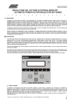
L1
L2
L3
Fan
N.O.
Auxiliary
Supply
Alarm
N.O.
N.C.
C
I3
I2
I1
M2
V3
V2
V1
L
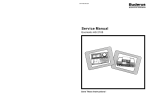
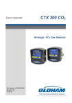
Inserzione trifase con 3 correnti
N
M1
1
2
3
4
5
6
7
8
9
1
5 A max
2
3
4
5
115 Vac or
230 Vac or
400 Vac
540 Vac max
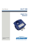
L1
L2
L3
Fan
N.O.
Auxiliary
Supply
Alarm
N.O.
N.C.
C
I3
I2
I1
M2
V3
V2
V1
L
N
M1
1
2
3
4
5
6
7
8
5 A max
9
1
2
3
4
540 Vac max
5
115 Vac or
230 Vac or
400 Vac
9
Inserzione trifase con 2 correnti
(Aron)
GB
ITALFARAD S.p .A. via IV novembre n.1 Minerbio (BO) It aly
English
A single module for 3-phase measurements and electrical panels
protection
11
Front Panel Display and Keys
11
Operation Mode
12
Getting started and parameters setup
14
Technical Characteristics
15
10
GB
ITALFARAD S.p .A. via IV novembre n.1 Minerbio (BO) It aly
SPC2
Control and Protection Instrument
A single module for 3-phase measurements and electrical panels
protection.
The SPC2 device has been designed to
protect the electrical panels and electrical
plants, mainly the power factor regulation
and filtering plants, by mean of continuous
monitoring of line voltage, line current
(amplitude and harmonics) and temperature.
The voltage value is compared with a threshold value programmable, giving an alarm
when exceeded.
Current value is processed to calculate the
RMS amplitude and the total harmonic distortion THD: when a maximum short-circuit
and current distortion threshold is exceeded
an alarm output is generated.
Temperature value, transduced by means of
an internal probe, is monitored to activate
cooling devices (fan, etc...) when a programmable pre-alarm threshold is exceeded and
to produce an alarm if a programmable maximum value is exceeded. All measurements
and alarms are displayed on the front panel
display. Working parameters setup is accomplished using 4 functional keys.
Small size (DIN 96x96 mm) and low cost make SPC2 ideal to use in all industrial and civil electrical plants.
Front Panel Display and Keys
MEASUREMENTS LED
V, I, THD%,
Iharm, Hz, °T
L1, L2, L3
x 1000
Indicate the measure currently showed on 3-digit display: voltage, current, harmonic distortion, temperature, harmonic current and net frequency.
Indicate the phase of the measure currently showed on 3-digit display. In
Voltage Measurements, the concurrent lighting of two leds indicates the
channels wich the phase-phase voltage is referred to (for ex. L1-L2 indicates V12 voltage).
Multiplier x 1000 of the measure currently displayed.
STATUS LED
FAN
Indicates that the pre-alarm temperature threshold has been exceeded and
the cooling devices are activated.
MANUAL
RESET
On: the manual reset of alarms is selected.
Off: the automatic reset alarm (when the alarm condition disappears) is
selected (except over-temperature alarm, always manual resettable)
ALARM
Blinks together with the alarmed measure to indicate that an alarm condition
has occurred.
11
GB
ITALFARAD S.p .A. via IV novembre n.1 Minerbio (BO) It aly
KEYS
RESET/PHASE
+/MAX
-/MIN
SCROLL
If pressed for 5 seconds in measure session, makes a reset of alarms and
max/min values; if pressed during the setup session, forces the default
value of the currently edited parameter. If pressed at the power-on, forces
the default programming.
In measure session visualizes the maximum value reached by the correspondent measure. During setup session increases the parameter value.
In measure session visualizes the minimum value reached by the correspondent measure. During setup session decreases the parameter value.
Selects the measure to be showed on 3-digit display. During setup session, selects the parameter to be programmed.
SPECIAL KEYS (two keys pressed)
SCROLL
with +/MAX
SCROLL
with -/MIN
+/MAX
with -/MIN
RESET/PHASE
with SCROLL
RESET/PHASE
with +/MAX
RESET/PHASE
with -/MIN
If pressed for 10 seconds, enters the setup session
Defines the actual measure as default measure to be displayed at the poweron.
Starts the cyclic scanning of all the measure on the display every 3 seconds.
If pressed on power on changes connection mode (1-phase or 3-phase).
Activates manually the cooling devices relay.
Deactivates manually the cooling devices relay.
Operation Mode
Voltage protection
The input line voltage, measured in true RMS, is compared with the threshold value programmed. If the voltage exceedes the threshold for a time
longer than 30 minutes, an alarm is produced (voltage and alarm leds blinking) and the alarm relay is opened.
Current protection
The input current, measured in true RMS, is compared with the reference
value set at 120% of nominal value (the primary current of CT). If the current
exceedes the threshold for a time longer than 3 seconds, an alarm is produced (current and alarm leds blinking) and the alarm relay is opened.
THD protection
The current signal is processed to extract the total distortion value. Such a
value is compared with the programmed threshold: if the THD value exceedes the actual threshold (THD% High Current Threshold or THD% Low
Current Threshold) for a time longer than programmed, an alarm is produced (thd and alarm leds blinking) and the alarm relay is opened.
Temperature
protection
Temperature value is compared with the temperature threshold programmed: if the temperature value exceedes the threshold for a time longer than
10 seconds, the FAN is lighted and the FAN relay is closed. If the temperature exceedes the sum of threshold and deltaT, an alarm is produced (T and
alarm leds blinking), the alarm relay is closed and the FAN realy is opened.
This alarm can only be restored manually.
12
GB
ITALFARAD S.p .A. via IV novembre n.1 Minerbio (BO) It aly
All protections have integral times, i.e. they keep into account the previous exceeding the alarm times, as indicated in the following figure:
Operation
timings
It's possible to clear manually the integral time pressing the RESET/PHASE key
or automatically after that a time longer than the trigger time is elapsed without
alarm occurrences.
Alarm RESET
When an alarm occurs, the instrument signals the condition with a
blinking of the alarm led and of the led related to the measure on
alarm and the alarm relay is opened.
Till tha alarm condition is valid the device automatically turns, after
10 sec. of inactivity, on the visualization of the measure that caused
it.
Three alarm reset are possible: manual reset (MAn) by pressing the
RESET/PHASE key (for 5 seconds), or automatic (AU1 or AU2)
reset when the alarm condition disappears. In this case, if more than
3 alarms occur within one hour, a manual reset is requested, to
notify an abnormal condition with a possible fault into the electrical
system (this is not true for voltage alarm in AU2 mode, the only difference versus AU1 mode).
The over-temperature alarm always needs a manual reset.
How to select the
default display measure
To define the measure to be displayed as default measure at the
power-on, select the measure and then press the key SCROLL
togheter with the key -/MIN .
Periodic scanning of In 3-phase mode, to activate the periodic scanning of the phase
the measures on the measures on the display every 3 seconds, press the key +/MAX
togheter with the key -/MIN . To stop the scanning, press any key.
display
Cooling device testing
It's possible to activate manually, for testing purpose, the relay of
cooling devices (fan, ...): to do this, press the key RESET/PHASE
togheter with +/MAX. To deactivate the relay, press RESET/PHASE
togheter with -/MIN
13
GB
ITALFARAD S.p .A. via IV novembre n.1 Minerbio (BO) It aly
Getting started and parameters setup
Wire the device to plant (see diagrams on next page) and apply power: the SPC2 automatically
starts in measure mode showing the default measure.
To access the setup functions, press the key SCROLL togheter with the key +/MAX for 10 seconds: once the setup mode is entered, the device will blank the measure leds and light-up the
leds corresponding to the parameters to be programmed, showing their current values.
The correspondence between parameters to be programmed and the measures leds is shown in
the table below:
Parameter
Led
Voltage Threshold
Led V
Primary Current of CT
Led I
THD Threshold for High Currents
Led THD%
Delay THD
Led THD% with Led Iharm
T° Threshold
Led T°
Delta T° Threshold
Led T° with Led Iharm
Alarm Reset Type (AUT/MAN)
TV Ratio (/100V)
All leds off
Current Threshold between Quad. Low I – Quad. High I
Led I blinking
THD Threshold for Low Currents
Led THD% blinking
Temperature Offset Parameter
Led T° blinking
Led V blinking
Use the keys +/MAX and -/MIN to change the value of actual parameter and the keys SCROLL
to access the next parameters. Pressing the key RESET/PHASE (for 5 seconds) will force the
default value of the parameter.
To exit the setup mode, wait for 10 seconds without pressing any key: finally the device will come
back to measure mode.
The following table shows the programmable values for each parameter:
Name
Parameter
Programmable Values
V
Voltage Threshold
CT
Primary Current of CT
THD% HIGH THD Threshold for High Currents
DELAY
°T
Trip Time THD Alarm
from 360 to 480 Volt
from 5 to 10k Amp
from 5% to 250%
from 5 to 900 sec.
Temperature Threshold for cooling device from 25 °C to 50 °C
Over-Temperature Threshold (delta value
from 0 °C to 30 °C
° T
respect to Temperature Threshold)
AU1 = Automatic reset,
mode 1
AU2 = Automatic reset,
AUT/MAN Alarm Reset Type
mode 2
MAn = Manual reset with
RESET/PHASE key
VT
TV Ratio (/100V)
{1; 2.2; 3.8; 4.4; 5; 6; 8; 10}
Current Threshold (in % of nominal value)
I% H-L
from 0% to 100%
between Low I and High I.
THD% LOW THD Threshold for Low Currents
from 5% to 250%
OFFTEMP
Temperature Offset Parameter
from -30 °C to 30 °C
14
Default
440 V
600 A
35%
120 sec.
35 °C
25 °C
AU1
1
10%
70%
0 °C
GB
ITALFARAD S.p .A. via IV novembre n.1 Minerbio (BO) It aly
Technical Characteristics
115/230/400 Vac (depending on model) ± 10% 50/60 Hz
4 VA
96 x 96 x 60 mm. DIN 43700
450 g
3 inputs 400 V ± 10% phase to phase, 50/60 Hz
> 1 MΩ
3 inputs from external CT /5A
20% permanent
< 0.25 VA
±1% f.s.
±1% f.s.
10 mA x CT/5
±1% f.s. for Irms > 10% f.s.; ±5% f.s. for Irms < 10% f.s
±1 °C
0.2% f.s.
±1 sec.
5 A 250 V NO
5 A 250 V NO and NC
Removable terminals
Requires specific external adapter
from 0°C to +55°C
95% uncondensed
from –20°C to +70°C
Power Supply
Consumption
Size
Weight
Voltage input
Voltage input impedance
Current input
Current overload
Current circuit consumption
Voltage accuracy
Current accuracy
Current resolution
Current THD accuracy
Temperature accuracy
Frequency accuracy
Timing accuracy
Cooling device relay contacts
Alarm relays contacts
Wirings
RS232 Communications
Working temperature
Umidity
Storage temperature
L1
L2
L3
Fan
N.O.
Auxiliary
Supply
Alarm
N.O.
N.C.
C
I3
I2
I1
M2
V3
V2
V1
L
3 Currents wiring diagram
N
M1
1
2
3
4
5
6
7
8
9
1
5 A max
2
3
4
5
115 Vac or
230 Vac or
400 Vac
540 Vac max
L1
L2
L3
Fan
N.O.
Auxiliary
Supply
Alarm
N.O.
N.C.
C
I3
I2
I1
M2
V3
V2
V1
L
N
M1
1
2
3
4
5
6
7
8
5 A max
9
1
2
3
4
540 Vac max
5
115 Vac or
230 Vac or
400 Vac
15
2 Currents (Aron) wiring diagram
ITALFARAD S.p .A. via IV novembre n.1 Minerbio (BO) It aly
Via IV novembre, 1
40061 Minerbio Bo Italy
Tel. ++39 051 6618311
Fax ++39 051 6605594
E-mail: [email protected]
Web: http://www.italfarad.com
1607-2005
Edizione