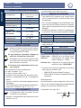
1
VEGA BUS
ISTRUZIONI PER L’USO - INSTRUCTIONS FOR USE
INSTRUCTIONS POUR L’USAGER - INSTRUCCIONES PARA EL USO
GEBRAUCHSANLEITUNG - GIDS VOOR DE GEBRUIKER
ITALIANO
AVVERTENZE PER L’INSTALLATORE
OBBLIGHI GENERALI PER LA SICUREZZA
ATTENZIONE! È importante per la sicurezza delle persone seguire attentamente tutta l’istruzione. Una errata installazione o un errato uso del prodotto
può portare a gravi danni alle persone.
1. Leggere attentamente le istruzioni prima di iniziare l’installazione del prodotto.
2. I materiali dell’imballaggio (plastica, polistirolo, ecc.) non devono essere lasciati alla
portata dei bambini in quanto potenziali fonti di pericolo.
3. Conservare le istruzioni per riferimenti futuri.
4. Questo prodotto è stato progettato e costruito esclusivamente per l’utilizzo indicato in
questa documentazione. Qualsiasi altro utilizzo non espressamente indicato potrebbe
pregiudicare l’integrità del prodotto e/o rappresentare fonte di pericolo.
5. GENIUS declina qualsiasi responsabilità derivata dall’uso improprio o diverso da quello
per cui l’automatismo è destinato.
6. Non installare l’apparecchio in atmosfera esplosiva: la presenza di gas o fumi infiammabili costituisce un grave pericolo per la sicurezza.
7. Gli elementi costruttivi meccanici devono essere in accordo con quanto stabilito dalle
Norme EN 12604 e EN 12605.
8. Per i Paesi extra-CEE, oltre ai riferimenti normativi nazionali, per ottenere un livello di
sicurezza adeguato, devono essere seguite le Norme sopra riportate.
9. GENIUS non è responsabile dell’inosservanza della Buona Tecnica nella costruzione
delle chiusure da motorizzare, nonché delle deformazioni che dovessero intervenire
nell’utilizzo.
10. L’installazione deve essere effettuata nell’osservanza delle Norme EN 12453 e EN
12445. Il livello di sicurezza dell’automazione deve essere C+D.
11. Prima di effettuare qualsiasi intervento sull’impianto, togliere l’alimentazione elettrica
e scollegare le batterie.
12. Prevedere sulla rete di alimentazione dell’automazione un interruttore onnipolare con
distanza d’apertura dei contatti uguale o superiore a 3 mm. È consigliabile l’uso di un
magnetotermico da 6A con interruzione onnipolare.
13. Verificare che a monte dell’impianto vi sia un interruttore differenziale con soglia da
0,03 A.
14. Verificare che l’impianto di terra sia realizzato a regola d’arte e collegarvi le parti metalliche della chiusura.
15. L’automazione dispone di una sicurezza intrinseca antischiacciamento costituita da un
controllo di coppia. E’ comunque necessario verificarne la sogli di intervento secondo
quanto previsto dalle Norme indicate al punto 10.
16. I dispositivi di sicurezza (norma EN 12978) permettono di proteggere eventuali aree
di pericolo da Rischi meccanici di movimento, come ad Es. schiacciamento, convogliamento, cesoiamento.
17. Per ogni impianto è consigliato l’utilizzo di almeno una segnalazione luminosa nonché
di un cartello di segnalazione fissato adeguatamente sulla struttura dell’infisso, oltre
ai dispositivi citati al punto “16”.
18. GENIUS declina ogni responsabilità ai fini della sicurezza e del buon funzionamento
dell’automazione, in caso vengano utilizzati componenti dell’impianto non di produzione
GENIUS.
19. Per la manutenzione utilizzare esclusivamente parti originali GENIUS.
20. Non eseguire alcuna modifica sui componenti facenti parte del sistema
d’automazione.
21. L’installatore deve fornire tutte le informazioni relative al funzionamento manuale del
sistema in caso di emergenza e consegnare all’Utente utilizzatore dell’impianto il libretto
d’avvertenze allegato al prodotto.
22. Non permettere ai bambini o persone di sostare nelle vicinanze del prodotto durante
il funzionamento.
23. L’applicazione non può essere utilizzata da bambini, da persone con ridotte capacità
fisiche, mentali, sensoriali o da persone prive di esperienza o del necessario
addestramento.
24. Tenere fuori dalla portata dei bambini radiocomandi o qualsiasi altro datore di impulso,
per evitare che l’automazione possa essere azionata involontariamente.
25. Il transito tra le ante deve avvenire solo a cancello completamente aperto.
26. L’utente utilizzatore deve astenersi da qualsiasi tentativo di riparazione o d’intervento
e deve rivolgersi solo ed esclusivamente a personale qualificato GENIUS o centri
d’assistenza GENIUS.
27. Tutto quello che non è previsto espressamente in queste istruzioni non è permesso.
ENGLISH
IMPORTANT NOTICE FOR THE INSTALLER
GENERAL SAFETY REGULATIONS
ATTENTION! To ensure the safety of people, it is important that you read all
the following instructions. Incorrect installation or incorrect use of the product could cause serious harm to people.
1. Carefully read the instructions before beginning to install the product.
2. Do not leave packing materials (plastic, polystyrene, etc.) within reach of children
as such materials are potential sources of danger.
3. Store these instructions for future reference.
4. This product was designed and built strictly for the use indicated in this documentation.
Any other use, not expressly indicated here, could compromise the good condition/
operation of the product and/or be a source of danger.
5. GENIUS declines all liability caused by improper use or use other than that for which
the automated system was intended.
6. Do not install the equipment in an explosive atmosphere: the presence of inflammable
gas or fumes is a serious danger to safety.
7. The mechanical parts must conform to the provisions of Standards EN 12604 and EN
12605.
8. For non-EU countries, to obtain an adequate level of safety, the Standards mentioned
above must be observed, in addition to national legal regulations.
9. GENIUS is not responsible for failure to observe Good Technique in the construction
of the closing elements to be motorised, or for any deformation that may occur during
use.
10. The installation must conform to Standards EN 12453 and EN 12445. The safety level
of the automated system must be C+D.
11. Before attempting any job on the system, cut out electrical power and disconnect the
batteries.
12. The mains power supply of the automated system must be fitted with an all-pole switch
with contact opening distance of 3mm or greater. Use of a 6A thermal breaker with
all-pole circuit break is recommended.
13. Make sure that a differential switch with threshold of 0.03 A is fitted upstream of the
system.
14. Make sure that the earthing system is perfectly constructed, and connect metal parts
of the means of the closure to it.
15. The automated system is supplied with an intrinsic anti-crushing safety device consisting
of a torque control. Nevertheless, its tripping threshold must be checked as specified
in the Standards indicated at point 10.
16. The safety devices (EN 12978 standard) protect any danger areas against mechanical
movement Risks, such as crushing, dragging, and shearing.
17. Use of at least one indicator-light is recommended for every system, as well as a
warning sign adequately secured to the frame structure, in addition to the devices
mentioned at point “16”.
18. GENIUS declines all liability as concerns safety and efficient operation of the automated
system, if system components not produced by GENIUS are used.
19. For maintenance, strictly use original parts by GENIUS.
20. Do not in any way modify the components of the automated system.
21. The installer shall supply all information concerning manual operation of the system in
case of an emergency, and shall hand over to the user the warnings handbook supplied
with the product.
22. Do not allow children or adults to stay near the product while it is operating.
23. The application cannot be used by children, by people with reduced physical, mental,
sensorial capacity, or by people without experience or the necessary training.
24. Keep remote controls or other pulse generators away from children, to prevent the
automated system from being activated involuntarily.
25. Transit through the leaves is allowed only when the gate is fully open.
26. The User must not in any way attempt to repair or to take direct action and must solely
contact qualified GENIUS personnel or GENIUS service centres.
27. Anything not expressly specified in these instructions is not permitted.
FRANÇAIS
CONSIGNES POUR L’INSTALLATEUR
RÈGLES DE SÉCURITÉ
ATTENTION! Il est important, pour la sécurité des personnes, de suivre à la
lettre toutes les instructions. Une installation erronée ou un usage erroné
du produit peut entraîner de graves conséquences pour les personnes.
1. Lire attentivement les instructions avant d’installer le produit.
2. Les matériaux d’emballage (matière plastique, polystyrène, etc.) ne doivent pas être
laissés à la portée des enfants car ils constituent des sources potentielles de
danger.
3. Conserver les instructions pour les références futures.
4. Ce produit a été conçu et construit exclusivement pour l’usage indiqué dans cette
documentation. Toute autre utilisation non expressément indiquée pourrait compromettre l’intégrité du produit et/ou représenter une source de danger.
5. GENIUS décline toute responsabilité qui dériverait d’usage impropre ou différent de
celui auquel l’automatisme est destiné.
6. Ne pas installer l’appareil dans une atmosphère explosive: la présence de gaz ou de
fumées inflammables constitue un grave danger pour la sécurité.
7. Les composants mécaniques doivent répondre aux prescriptions des Normes EN
12604 et EN 12605.
8. Pour les Pays extra-CEE, l’obtention d’un niveau de sécurité approprié exige non
seulement le respect des normes nationales, mais également le respect des Normes
susmentionnées.
9. GENIUS n’est pas responsable du non-respect de la Bonne Technique dans la construction des fermetures à motoriser, ni des déformations qui pourraient intervenir lors
de l’utilisation.
10. L’installation doit être effectuée conformément aux Normes EN 12453 et EN 12445.
Le niveau de sécurité de l’automatisme doit être C+D.
11. Couper l’alimentation électrique et déconnecter la batterie avant toute intervention sur
l’installation.
12. Prévoir, sur le secteur d’alimentation de l’automatisme, un interrupteur omnipolaire
avec une distance d’ouverture des contacts égale ou supérieure à 3 mm. On recommande d’utiliser un magnétothermique de 6A avec interruption omnipolaire.
13. Vérifier qu’il y ait, en amont de l’installation, un interrupteur différentiel avec un seuil
de 0,03 A.
14. Vérifier que la mise à terre est réalisée selon les règles de l’art et y connecter les pièces
métalliques de la fermeture.
15. L’automatisme dispose d’une sécurité intrinsèque anti-écrasement, formée d’un contrôle
du couple. Il est toutefois nécessaire d’en vérifier le seuil d’intervention suivant les
prescriptions des Normes indiquées au point 10.
16. Les dispositifs de sécurité (norme EN 12978) permettent de protéger des zones éventuellement dangereuses contre les Risques mécaniques du mouvement, comme
l’écrasement, l’acheminement, le cisaillement.
17. On recommande que toute installation soit doté au moins d’une signalisation lumineuse,
d’un panneau de signalisation fixé, de manière appropriée, sur la structure de la fermeture, ainsi que des dispositifs cités au point “16”.
18. GENIUS décline toute responsabilité quant à la sécurité et au bon fonctionnement de
l’automatisme si les composants utilisés dans l’installation n’appartiennent pas à la
production GENIUS.
19. Utiliser exclusivement, pour l’entretien, des pièces GENIUS originales.
20. Ne jamais modifier les composants faisant partie du système d’automatisme.
21. L’installateur doit fournir toutes les informations relatives au fonctionnement manuel
du système en cas d’urgence et remettre à l’Usager qui utilise l’installation les “Instructions pour l’Usager” fournies avec le produit.
22. Interdire aux enfants ou aux tiers de stationner près du produit durant le
fonctionnement.
23. Ne pas permettre aux enfants, aux personennes ayant des capacités physiques, mentales et sensorielles limitées ou dépourvues de l’expérience ou de la formation nécessaires d’utiliser l’application en question.
24. Eloigner de la portée des enfants les radiocommandes ou tout autre générateur d’impulsions, pour éviter tout actionnement involontaire de l’automatisme.
25. Le transit entre les vantaux ne doit avoir lieu que lorsque le portail est complètement
ouvert.
26. L’utilisateur doit s’abstenir de toute tentative de réparation ou d’intervention et doit
s’adresser uniquement et exclusivement au personnel qualifié GENIUS ou aux centres
d’assistance GENIUS.
27. Tout ce qui n’est pas prévu expressément dans ces instructions est interdit.
ESPAÑOL
ADVERTENCIAS PARA EL INSTALADOR
REGLAS GENERALES PARA LA SEGURIDAD
ATENCION! Es sumamente importante para la seguridad de las personas
seguir atentamente las presentes instrucciones. Una instalación incorrecta
o un uso impropio del producto puede causar graves daños a las
personas.
1. Lean detenidamente las instrucciones antes de instalar el producto.
2. Los materiales del embalaje (plástico, poliestireno, etc.) no deben dejarse al alcance
de los niños, ya que constituyen fuentes potenciales de peligro.
VEGA BUS
Pag. 3
Immagini - Images - Images - Imágenes - Bilder - Afbeeldingen
m
35 m
25
m
m
105 mm
1
Ø16 Max.
Fig. 01
Fig. 02
1
Ø16 Max.
Fig. 03
TX
RX
DL2
DL1
ON
1 2 3 4
DL2
RX-TX
DS1
BUS BUS
ON
DS1
1 2 3 4
DL1= A
llineamento - Alignment - Alignement
Alineación - Ausrichtung - Vitgelijnd
DL2= Stato bus/Alimentazione
Bus/power supply status
Etat bus/Alimentation
Estado bus/alimentación
Status bus-leitung/versorgung
Status bus/voeding
DS1= Dip switches di settaggio
Setting dip switches
Dip switches de réglage
Dip switches de configuración
Dip switches für die einstellung
Dipschakelaars voor instelling
BUS BUS
Apparecchiatura elettronica - Control unit
Armoire èlectronique - Equipo electrónico
Elektronisches steuergerät
Elektronische apparatuur
Fig. 04
Pagina 4
VEGA BUS
Guida per l’installatore
ITALIANO
CARATTERISTICHE TECNICHE
Da collegamento BUS GWay, a due fili non polarizzati 24V
Assorbimento (mA)
10
Portata massima (m)
15
Grado di protezione
IP54
Tempo rilevamento
20
ostacolo (msec.)
Modalità
di
Automatica
allineamento
±7° (15m)
Angolo di auto
•Per il collegamento con la scheda di comando
fare riferimento alle relative istruzioni.
MESSA IN FUNZIONE
Alimentazione
allineamento
±13° (5m)
Te m p e r a t u r a
funzionamento
Installazione
Dimensioni
di
-20 +55
A parete
Vedi fig. 1
INSTALLAZIONE
Queste fotocellule possono essere utilizzate unicamente con apparecchiature Genius
con tecnologia BUS G-WAY.
Su ogni impianto è possibile collegare al
massimo 16 coppie di fotocellule.
Per definire il tipo di funzionamento delle
fotocellule fare riferimento alle istruzioni
della centrale di comando.
Il ricevitore ed il trasmettitore devono essere allineati.
Sono possibili due tipi di installazione:
Con tubo incassato, Fig. 2.
Con tubo o guaina esterni, fig. 3.
In entrambi i casi procedere nel seguente modo:
•Eseguire le predisposizioni per i collegamenti
elettrici.
•Fissare i contenitori utilizzando adeguati sistemi
di fissaggio.
•I fili di collegamento devono passare attraverso il
passacavo in dotazione (fig. 2 e 3 rif. a).
COLLEGAMENTI
Il collegamento BUS è costituito da due
conduttori non polarizzati.
•Eseguire il collegamento delle fotocellule come
indicato in Fig. 4
•Il dip switch DS1 presente sulle schede determina il comportamento e l’indirizzo della coppia
di fotocellule.
•Per il corretto settaggio dei dip-switch fare riferimento alle istruzioni della centrale di comando.
•Ogni coppia di fotocellule deve avere il medesimo
settaggio.
•Alimentare il sistema e verificare il comportamento del led DL2 secondo quanto riportato in tabella:
Stato
Acceso fisso
Lampeggiante
Spento
Descrizione
Funzionamento corretto
Collegamento BUS errato
Non funziona/scollegato
•Controllare il led DL1 per il corretto allineamento
delle fotocellule:
Stato
Acceso
Spento
Descrizione
Allineamento corretto
Allineamento non corretto
DICHIARAZIONE DI CONFORMITÀ
Fabbricante:
GENIUS S.p.A. con Socio Unico
Indirizzo:
Via Padre Elzi, 32 - 24050 - Grassobbio- Bergamo - ITALIA
Dichiara che:Il dispositivo di protezione optoelettronico mod. VEGA-BUS
•è conforme ai requisiti essenziali di sicurezza
delle seguenti direttive CEE:
• 2006/95/CE direttiva Bassa Tensione.
• 2004/108/CE direttiva Compatibilità Elettromagnetica
Nota aggiuntiva:
Questo prodotto è stato sottoposto a test di controllo in una configurazione tipica omogenea (tutti
prodotti di costruzione GENIUS S.p.A.)
Grassobbio, 04 Luglio 2011
L’Amministratore Delegato
Enrico Nardi
VEGA BUS
Pagina 5
Guide for the installer
Power supply
Absorption (mA)
Max. range (m)
Protection class
Obstacle detection
time (msec.)
Alignment
f r o m B U S G - Wa y
connection, with two 24V
non-polarised wires
10
15
IP54
20
Automatic
±7° (15m)
Self-alignment angle
±13° (5m)
Operating ambient
temperature
Installation
Dimensions
-20 +55
Wall-mounted
See fig. 1
INSTALLATION
These photocells can only be used with
Genius equipment featuring a BUS G-WAY
technology.
A max. of 16 pairs of photocells can be
connected on each system.
To set the operating mode of the photocells,
refer to the instructions of the control unit.
The receiver and the transmitter must be
aligned.
Two installation types are possible:
With recessed tube, Fig. 2.
With external tube or external sheath, fig. 3.
In both cases operate as follows:
•Prepare the electrical connections.
•Secure the housings by means of suitable
fastening systems.
•The connection wires must be routed through
the supplied cable gland (fig. 2 and 3 ref. a).
•The dip-switch DS1, which is located on the
boards, determines the behaviour and the
address of the photocell pairs.
•For a correct set-up of the dip-switches, refer to
the instructions of the control unit.
•Each pair of photocells must have the same
setting.
•Power up the system and check the behaviour of
DL2 LED according to the table below:
Status
Steady light
Flashing
OFF
Description
Correct operations
Incorrect BUS connection
Does not operate/disconnected
•Check LED DL1 for the correct alignment of the
photocells:
Status
ON
OFF
Description
Correct alignment
Incorrect alignment
DECLARATION OF CONFORMITY
Manufacturer:GENIUS S.p.A. con Socio Unico
Address:
Via Padre Elzi, 32 - 24050 Grassobbio- Bergamo - ITALY
Declares that:T he optoelectronic protection
device mod. VEGA-BUS
•complies with the essential safety requirements
of the following EEC directives:
• 2006/95/EC Low Voltage Directive.
• 2004/108/EC Electromagnetic Compatibility
Directive
Additional note:
This product underwent tests in a typical
homogeneous configuration (all products
manufactured by GENIUS S.p.A.)
CONNECTIONS
The BUS connection is formed by two
non-polarised conductors
•Connect the photocells as shown in Fig. 4
•For the connection to the control board refer to
the specific instructions.
Grassobbio, 04 July 2011
Managing Director
Enrico Nardi
ENGLISH
START-UP
TECHNICAL SPECIFICATIONS
Pagina 6
VEGA BUS
Guide pour l’installateur
CARACTÉRISTIQUES TECHNIQUES
Alimentation
Absorption (mA)
Portée maximale (m)
Degré de protection
Délai de détection de
présence (msec.)
Modalité
d’alignement
Angle d’alignement
automatique
FRANÇAIS
Température
d’utilisation
Installation
Dimensions
Depuis la connexion BUS
G-Way, à deux fils non
polarisés 24V
10
15
IP54
20
Automatique
±7° (15m)
±13° (5m)
-20 +55
À paroi
Voir figure 1
INSTALLATION
Ces photocellules sont à utiliser uniquement
avec des appareils Genius, équipés de la
technologie BUS G-WAY.
Pour chaque installation, il est possible de
connecter 16 couples de photocellules,
au maximum.
Pour déterminer le type de fonctionnement
des photocellules, veuillez vous reporter
aux instructions de la centrale de
commande.
Le récepteur et le transmetteur doivent être
alignés.
Les types d’installation sont au nombre de deux :
Avec canalisation encastrée, Fig. 2.
Avec canalisation ou gaines externes, fig. 3.
Dans les deux cas, il faudra procéder comme suit :
•Exécuter les prédispositions pour les connexions
électriques.
•Fixer les boîtiers moyennant des systèmes de
fixation adéquats.
•Les fils de connexion doivent passer à travers
le passe-câbles fourni (Figures 2 et 3 réf. a).
•Pour la connexion avec la carte de commande,
veuillez vous reporter aux instructions relatives
pour l’emploi.
MISE EN FONCTION
•Le DIP-SWITCHE DS1, intégré aux cartes,
détermine le comportement et l’adresse du
couple de photocellules.
•Pour correctement régler les DIP-SWITCHES,
veuillez vous reporter aux instructions de la
centrale de commande.
•Chaque couple de photocellule doit avoir le
même réglage.
•Alimenter le système et vérifier le comportement
de la led DL2, selon ce qui est rapporté dans le
tableau ci-après :
État
Allumée fixe
Clignotante
Éteinte
Description
Fonctionnement correct
Connexion BUS erronée
Aucun fonctionnement/
déconnectée
•Contrôler la led DL1 pour correctement aligner
les photocellules :
État
Allumée
Éteinte
Description
Alignement correct
Alignement erroné
DÉCLARATION DE CONFORMITÉ
Fabricant :GENIUS S.p.A. con Socio Unico
Adresse :Via Padre Elzi, 32 - 24050 Grassobbio- Bergamo - ITALIE
Declare que :le dispositif de protection
opto-électronique mod. VEGA-BUS
•est conforme aux exigences essentielles de
sécurité, dont aux directives CEE ci-après :
• 2006/95/CE directive Basse Tension.
• 2004/108/CE directive Compatibilité
Électro-magnétique
Note additionnelle :
Ce produit a fait l’objet de tests de contrôle, dans
une configuration typique homogène (tous les
produits sont fabriqués par GENIUS S.p.A.)
CONNEXIONS
La connexion BUS comprend deux
conducteurs non polarisés.
•Effectuer la connexion des photocellules, comme
il est précisé à la Fig. 4
Grassobbio, le 04 juillet 2011
L’Administrateur délégué
Enrico Nardi
VEGA BUS
Pagina 7
Guía para el instalador
De conexión BUS G-Way,
Alimentación
a dos hilos no polarizados
24V
Absorción (mA)
10
Capacidad máxima (m)
15
Grado de protección
IP54
Tiempo de detección
20
del obstáculo (mseg.)
Modo de alineación
Automático
±7° (15m)
Ángulo de
auto-alineación
Temperatura ambiente
de funcionamiento
Instalación
Dimensiones
±13° (5m)
-20 +55
En pared
Véase fig. 1
INSTALACIÓN
Estas fotocélulas pueden ser utilizadas
exclusivamente en equipos Genius con
tecnología BUS G-WAY.
En cada equipo se pueden conectar al
máximo 16 pares de fotocélulas.
Para establecer el tipo de funcionamiento
de las fotocélulas consulte las instrucciones
de la central de mando.
El receptor y el transmisor han de estar
alineados
Son posibles dos tipos de instalación:
Con tubo encastrado, Fig. 2.
Con tubo o vaina externos, fig. 3.
En ambos casos proceda del siguiente modo:
•Realice las predisposiciones para las conexiones
eléctricas.
•Fije los contenedores por medio de adecuados
sistemas de fijación.
•Los hilos de conexión deben pasar a través del
pasacables suministrado en dotación (fig. 2 y
3 ref. a).
las correspondientes instrucciones.
PUESTA EN FUNCIONAMIENTO
•El dip switch DS1 presente en las tarjetas
determina el comportamiento y la dirección del
par de fotocélulas.
•Para configurar correctamente los dip-switch
consulte las instrucciones de la central de mando.
•Todos los pares de fotocélulas han de tener la
misma configuración.
•Alimente el sistema y compruebe el
comportamiento del diodo DL2 según lo indicado
en la tabla
Estado
Encendido fijo
Destellante
Apagado
Descripción
Funcionamiento correcto
Conexión BUS incorrecta
No funciona/desconectado
•Comprobar el diodo DL1 para la correcta
alineación de las fotocélulas:
Estado
Encendido
Apagado
Descripción
Alineación correcta
Alineación incorrecta
DECLARACIÓN DE CONFORMIDAD
Fabricante:
GENIUS S.p.A. con Socio Unico
Dirección:
Via Padre Elzi, 32 - 24050 Grassobbio- Bergamo - ITALIA
Declara que:El dispositivo de protección opto
electrónico mod. VEGA-BUS
•cumple con los requisitos esenciales de
seguridad de las siguientes directivas CEE:
• 2006/95/CE Directiva Baja Tensión.
• 2004/108/CE Directiva Compatibilidad
Electromagnética
Nota:
El presente producto ha sido sometido a ensayos
de control en una configuración típica uniforme
(todos los productos han sido fabricados por
GENIUS S.p.A.)
CONEXIONES
La conexión BUS está formada por dos
conductores no polarizados.
•Conecte las fotocélulas tal y como se indica en
la Fig. 4
•Para la conexión con la tarjeta de mando consulte
Grassobbio, 04 de Julio de 2011
El Administrador Delegado
Enrico Nardi
ESPAÑOL
CARACTERÍSTICAS TÉCNICAS
Pagina 8
VEGA BUS
Leitfaden für den Installateur
TECHNISCHE DATEN
ü b e r B U S - G - Wa y Verbindung mit zwei nicht
Versorgung
polarisierten Drähten, 24
V
Stromaufnahme (mA)
10
Maximale Reichweite (m)
15
Schutzart
IP54
Zeitraum für die
20
Erfassung eines
Hindernisses (msec)
Ausrichtung
automatisch
±7° (15m)
Selbstausrichtungswinkel
±13° (5m)
Temperatur am
-20 +55
Aufstellungsort
Montage
an der Wand
Abmessungen
siehe Abb. 1
INSTALLATION
Diese Fotozellen dürfen ausschließlich
mit Genius-Geräten mit BUS-G-WAYTechnologie verwendet werden.
Auf jeder Anlage können max. 16 Paar
Fotozellen angeschlossen werden.
DEUTSCH
Zum Festlegen der Betriebsweise der
Fotozellen wird auf die Anweisungen der
Steuereinheit verwiesen.
E m p f ä n g e r u n d S e n d e r m ü s s e n
ausgerichtet sein.
Möglich sind zwei Installationsarten:
mit Einbaurohr, Abb. 2.
mit externem Rohr oder externer Ummantelung
(Abb. 3).
In beiden Fällen sind folgende Schritte
auszuführen:
•Die Vorbereitungen für die elektrischen
Anschlüsse vornehmen.
•D i e G e h ä u s e m i t h i l f e g e e i g n e t e r
Befestigungssysteme fixieren.
•Die Verbindungsdrähte müssen durch die im
Lieferumfang enthaltene Kabeldurchführung
geführt werden (Abb. 2 und 3, Bez. a).
ANSCHLÜSSE
Die BUS-Verbindung besteht aus zwei nicht
polarisierten Leitern.
•Die Fotozellen gemäß den Angaben in Abb. 4
anschließen.
•Für den Anschluss der Steuerkarte wird auf die
entsprechenden Anweisungen verwiesen.
INBETRIEBNAHME
•Mit dem DIP-Schalter DS1 auf der Karte
werden das Verhalten und die Adresse des
Fotozellenpaars festgelegt.
•Für die korrekte Einstellung der DIP-Schalter
wird auf die Anweisungen der Steuereinheit
verwiesen.
•Jedes Fotozellenpaar muss dieselben
Einstellungen aufweisen.
•Das System mit Strom versorgen und das
Verhalten der LED DL2 gemäß den Angaben in
der Tabelle prüfen:
Status
Beschreibung
Dauerlicht einwandfreier Betrieb
Blinklicht BUS-Verbindung falsch
funktioniert nicht/ist
Aus
angeschlossen
nicht
•Die LED DL1 für die korrekte Ausrichtung der
Fotozellen prüfen:
Status
Ein
Aus
Beschreibung
korrekt ausgerichtet
nicht korrekt ausgerichtet
KONFORMITÄTSERKLÄRUNG
Hersteller:
GENIUS S.p.A. con Socio Unico
Adresse:
Via Padre Elzi, 32 - 24050 Grassobbio- Bergamo - ITALIEN
erklärt, dass: : d i e
optoelektronische
Schutzvorrichtung Mod. VEGA-BUS
•den wesentlichen Sicherheitsanforderungen der
folgenden EWG-Richtlinien entspricht:
• 2006/95/EG Niederspannung
• 2 0 0 4 / 1 0 8 / E G E l e k t r o m a g n e t i s c h e
Verträglichkeit
Hinweis:
Dieses Produkt wurde in einer typischen,
homogenen Konfiguration getestet (alle von
GENIUS S.p.A. hergestellten Produkte).
Grassobbio, 4. Juli 2011
Geschäftsführer
Enrico Nardi
VEGA BUS
Pagina 9
Gids voor de installateur
INBEDRIJFSTELLING
TECHNISCHE EIGENSCHAPPEN
BUS-aansluiting G-Way,
met
twee
nietgepolariseerde draden 24V
Opname (mA)
10
Maximale belasting (m)
15
Beschermingsgraad
IP54
Tijd detectie obstakel
20
(msec.)
Wijze van uitlijning
Automatisch
±7° (15m)
Hoek automatiche
Voeding
uitlijning
Bedrijfstemperatuur
Installatie
Afmetingen
±13° (5m)
-20 +55
Aan de wand
Zie (fig. 1)
INSTALLATIE
Deze fotocellen kunnen uitsluitend worden
gebruikt met Genius-apparatuur met
G-WAY BUS-technologie.
Op iedere installatie kunnen maximaal 16
paar fotocellen worden aangesloten.
Om het type werking van de fotocellen
te bepalen, zie de instructies van de
bedieningseenheid.
De ontvanger en de zender moeten op een
lijn zitten.
Er zijn twee typen installatie mogelijk:
Met ingemetselde leiding, Fig. 2.
Met externe leiding of kabelmantel, fig. 3.
Handel in beide gevallen als volgt:
•Voer alle voorbereidende handelingen voor de
elektrische aansluitingen uit.
•Bevestig de houders met behulp van geschikte
bevestigingssystemen,
•De aansluitkabels moeten door de bijgeleverde
kabelklem lopen (fig. 2 en 3 ref. a).
•Dipschakelaar DS1 op de kaart bepaalt het
gedrag en het adres van het paar fotocellen.
•Voor het correct instellen van de dipschakelaars,
zie de instructies van de bedieningseenheid.
•Ieder paar fotocellen moet hetzelfde zijn
ingesteld.
•Schakel de voeding naar het systeem en
in controleer het gedrag van led DL2 zoals
aangegeven de tabel:
Status
Blijft branden
Knippert
uit
Beschrijving
Werkt goed
Foute BUS-aansluiting
Werkt niet/niet aangesloten
•Controleer led DL1 om de fotocellen goed uit
te lijnen:
Status
Aan
uit
Beschrijving
Goed uitgelijnd
Niet goed uitgelijnd
VERKLARING VAN OVEREENSTEMMING
Fabrikant:
GENIUS S.p.A. con Socio Unico
Adres:
Via Padre Elzi, 32 - 24050 Grassobbio- Bergamo - ITALIË
Verklaart dat: d e o p t i s c h e - e l e k t r o n i s c h e
veiligheidsvoorziening mod.
VEGA-BUS
•in overeenstemming is met de fundamentele
veiligheidseisen van de volgende EEG-richtlijnen:
• 2006/95/EG Laagspanningsrichtlijn.
• 2004/108/CE Richtlijn elektromagnetische
compatibiliteit
Aanvullende opmerking:
Dit product is getest in een specifieke homogene
configuratie (dit geldt voor alle door GENIUS S.p.A.
vervaardigde producten).
AANSLUITINGEN
•Sluit de fotocellen aan zoals aangegeven in Fig. 4
•Zie voor de aansluiting op de bedieningskaart de
bijbehorende instructies.
Grassobbio, 04 juli 2011
De gedelegeerd bestuurder
Enrico Nardi
NEDERLANDS
De BUS-aansluiting bestaat uit twee
niet-gepolariseerde geleiders.
3. Guarden las instrucciones para futuras consultas.
4. Este producto ha sido proyectado y fabricado exclusivamente para la utilización indicada
en el presente manual. Cualquier uso diverso del previsto podría perjudicar el funcionamiento del producto y/o representar fuente de peligro.
5. GENIUS declina cualquier responsabilidad derivada de un uso impropio o diverso del
previsto.
6. No instalen el aparato en atmósfera explosiva: la presencia de gas o humos inflamables
constituye un grave peligro para la seguridad.
7. Los elementos constructivos mecánicos deben estar de acuerdo con lo establecido
en las Normas EN 12604 y EN 12605.
8. Para los países no pertenecientes a la CEE, además de las referencias normativas
nacionales, para obtener un nivel de seguridad adecuado, deben seguirse las Normas
arriba indicadas.
9. GENIUS no es responsable del incumplimiento de las buenas técnicas de fabricación
de los cierres que se han de motorizar, así como de las deformaciones que pudieran
intervenir en la utilización.
10. La instalación debe ser realizada de conformidad con las Normas EN 12453 y EN
12445.El nivel de seguridad de la automación debe ser C+D.
11. Quiten la alimentación eléctrica y desconecten las baterías antes de efectuar cualquier
intervención en la instalación.
12. Coloquen en la red de alimentación de la automación un interruptor omnipolar con
distancia de apertura de los contactos igual o superior a 3 mm. Se aconseja usar un
magnetotérmico de 6A con interrupción omnipolar.
13. Comprueben que la instalación disponga línea arriba de un interruptor diferencial con
umbral de 0,03 A.
14. Verifiquen que la instalación de tierra esté correctamente realizada y conecten las
partes metálicas del cierre.
15. La automación dispone de un dispositivo de seguridad antiaplastamiento constituido
por un control de par. No obstante, es necesario comprobar el umbral de intervención
según lo previsto en las Normas indicadas en el punto 10.
16. Los dispositivos de seguridad (norma EN 12978) permiten proteger posibles áreas de
peligro de Riesgos mecánicos de movimiento, como por ej. aplastamiento, arrastre,
corte.
17. Para cada equipo se aconseja usar por lo menos una señalización luminosa así como
un cartel de señalización adecuadamente fijado a la estructura del bastidor, además
de los dispositivos indicados en el “16”.
18. GENIUS declina toda responsabilidad relativa a la seguridad y al buen funcionamiento
de la automación si se utilizan componentes de la instalación que no sean de producción
GENIUS.
19. Para el mantenimiento utilicen exclusivamente piezas originales GENIUS
20. No efectúen ninguna modificación en los componentes que forman parte del sistema
de automación.
21. El instalador debe proporcionar todas las informaciones relativas al funcionamiento
del sistema en caso de emergencia y entregar al usuario del equipo el manual de
advertencias que se adjunta al producto.
22. No permitan que niños o personas se detengan en proximidad del producto durante
su funcionamiento.
23. La aplicación no puede ser utilizada por niños, personas con reducida capacidad física,
mental, sensorial o personas sin experiencia o la necesaria formación.
24. Mantengan lejos del alcance los niños los telemandos o cualquier otro emisor de impulso, para evitar que la automación pueda ser accionada involuntariamente.
25. Sólo puede transitarse entre las hojas si la cancela está completamente abierta.
26. El usuario debe abstenerse de intentar reparar o de intervenir directamente, y debe
dirigirse exclusivamente a personal cualificado GENIUS o a centros de asistencia
GENIUS.
27. Todo lo que no esté previsto expresamente en las presentes instrucciones debe entenderse como no permitido
DEUTSCH
HINWEISE FÜR DEN INSTALLATIONSTECHNIKER
ALLGEMEINE SICHERHEITSVORSCHRIFTEN
ACHTUNG! Um die Sicherheit von Personen zu gewährleisten, sollte die
Anleitung aufmerksam befolgt werden. Eine falsche Installation oder ein
fehlerhafter Betrieb des Produktes können zu schwerwiegenden Personenschäden führen.
1. Bevor mit der Installation des Produktes begonnen wird, sollten die Anleitungen aufmerksam gelesen werden.
2. Das Verpackungsmaterial (Kunststoff, Styropor, usw.) sollte nicht in Reichweite von
Kindern aufbewahrt werden, da es eine potentielle Gefahrenquelle darstellt.
3. Die Anleitung sollte aufbewahrt werden, um auch in Zukunft Bezug auf sie nehmen zu
können.
4. Dieses Produkt wurde ausschließlich für den in diesen Unterlagen angegebenen Gebrauch entwickelt und hergestellt. Jeder andere Gebrauch, der nicht ausdrücklich
angegeben ist, könnte die Unversehrtheit des Produktes beeinträchtigen und/oder eine
Gefahrenquelle darstellen.
5. Die Firma GENIUS lehnt jede Haftung für Schäden, die durch unsachgemäßen oder
nicht bestimmungsgemäßen Gebrauch der Automatik verursacht werden, ab.
6. Das Gerät sollte nicht in explosionsgefährdeten Umgebungen installiert werden: das
Vorhandensein von entflammbaren Gasen oder Rauch stellt ein schwerwiegendes
Sicherheitsrisiko dar.
7. Die mechanischen Bauelemente müssen den Anforderungen der Normen EN 12604
und EN 12605 entsprechen.
8. Für Länder, die nicht der Europäischen Union angehören, sind für die Gewährleistung
eines entsprechenden Sicherheitsniveaus neben den nationalen gesetzlichen Bezugsvorschriften die oben aufgeführten Normen zu beachten.
9. Die Firma GENIUS übernimmt keine Haftung im Falle von nicht fachgerechten
Ausführungen bei der Herstellung der anzutreibenden Schließvorrichtungen sowie bei
Deformationen, die eventuell beim Betrieb entstehen.
10. Die Installation muß unter Beachtung der Normen EN 12453 und EN 12445 erfolgen.
Die Sicherheitsstufe der Automatik sollte C+D sein.
11. Vor der Ausführung jeglicher Eingriffe auf der Anlage sind die elektrische Versorgung
und die Batterie abzunehmen.
12. Auf dem Versorgungsnetz der Automatik ist ein omnipolarer Schalter mit Öffnungsabstand der Kontakte von über oder gleich 3 mm einzubauen. Darüber hinaus wird der
Einsatz eines Magnetschutzschalters mit 6A mit omnipolarer Abschaltung empfohlen.
13. Es sollte überprüft werden, ob vor der Anlage ein Differentialschalter mit einer Auslöseschwelle von 0,03 A zwischengeschaltet ist.
14. Es sollte überprüft werden, ob die Erdungsanlage fachgerecht augeführt wurde. Die
Metallteile der Schließung sollten an diese Anlage angeschlossen werden.
15. Die Automation verfügt über eine eingebaute Sicherheitsvorrichtung für den
Quetschschutz, die aus einer Drehmomentkontrolle besteht. Es ist in jedem Falle erforderlich, deren Eingriffsschwelle gemäß der Vorgaben der unter Punkt 10 angegebenen Vorschriften zu überprüfen.
16. Die Sicherheitsvorrichtungen (Norm EN 12978) ermöglichen den Schutz eventueller
Gefahrenbereiche vor mechanischen Bewegungsrisiken, wie zum Beispiel Quetschungen, Mitschleifen oder Schnittverletzungen.
17. Für jede Anlage wird der Einsatz von mindestens einem Leuchtsignal empfohlen sowie
eines Hinweisschildes, das über eine entsprechende Befestigung mit dem Aufbau des
Tors verbunden wird. Darüber hinaus sind die unter Punkt “16” erwähnten Vorrichtungen
einzusetzen.
18. Die Firma GENIUS lehnt jede Haftung hinsichtlich der Sicherheit und des störungsfreien
Betriebs der Automatik ab, soweit Komponenten auf der Anlage eingesetzt werden,
die nicht im Hause GENIUS hergestellt urden.
19. Bei der Instandhaltung sollten ausschließlich Originalteile der Firma GENIUS verwendet
werden.
20. Auf den Komponenten, die Teil des Automationssystems sind, sollten keine Veränderungen vorgenommen werden.
21. Der Installateur sollte alle Informationen hinsichtlich des manuellen Betriebs des Systems in Notfällen liefern und dem Betreiber der Anlage das Anleitungsbuch, das dem
Produkt beigelegt ist, übergeben.
22. Weder Kinder noch Erwachsene sollten sich während des Betriebs in der unmittelbaren
Nähe der Automation aufhalten.
23. Die Anwendung darf nicht von Kindern, von Personen mit verminderter körperlicher,
geistiger, sensorieller Fähigkeit oder Personen ohne Erfahrungen oder der erforderlichen
Ausbildung verwendet werden.
24. Die Funksteuerungen und alle anderen Impulsgeber sollten außerhalb der Reichweite
von Kindern aufbewahrt werden, um ein versehentliches Aktivieren der Automation zu
vermeiden.
25. Der Durchgang oder die Durchfahrt zwischen den Flügeln darf lediglich bei vollständig
geöffnetem Tor erfolgen.
26. Der Benutzer darf direkt keine Versuche für Reparaturen oder Arbeiten vornehmen
und hat sich ausschließlich an qualifiziertes Fachpersonal GENIUS oder an Kundendienstzentren GENIUS zu wenden.
27. Alle Vorgehensweisen, die nicht ausdrücklich in der vorliegenden Anleitung vorgesehen
sind, sind nicht zulässig
NEDERLANDS
WAARSCHUWINGEN VOOR DE INSTALLATEUR
ALGEMENE VEILIGHEIDSVOORSCHRIFTEN
LET OP! Het is belangrijk voor de veiligheid dat deze hele instructie zorgvuldig
wordt opgevolgd. Een onjuiste installatie of foutief gebruik van het product
kunnen ernstig persoonlijk letsel veroorzaken.
1. Lees de instructies aandachtig door alvorens te beginnen met de installatie van het
product.
2. De verpakkingsmaterialen (plastic, polystyreen, enz.) mogen niet binnen het bereik
van kinderen worden gelaten, want zij vormen een mogelijke bron van gevaar.
3. Bewaar de instructies voor raadpleging in de toekomst.
4. Dit product is uitsluitend ontworpen en gebouwd voor het doel dat in deze documentatie
wordt aangegeven. Elk ander gebruik, dat niet uitdrukkelijk wordt vermeld, zou het
product kunnen beschadigen en/of een bron van gevaar kunnen vormen.
5. GENIUS aanvaardt geen enkele aansprakelijkheid voor schade die ontstaat uit oneigenlijk gebruik of ander gebruik dan waarvoor het automatische systeem is bedoeld.
6. Installeer het apparaat niet in een explosiegevaarlijke omgeving: de aanwezigheid van
ontvlambare gassen of dampen vormt een ernstig gevaar voor de veiligheid.
7. De mechanische bouwelementen moeten in overeenstemming zijn met de bepalingen
van de normen EN 12604 en EN 12605.
8. Voor niet-EEG landen moeten, om een goed veiligheidsniveau te bereiken, behalve
de nationale voorschriften ook de bovenstaande normen in acht worden genomen.
9. GENIUS is niet aansprakelijk als de regels der goede techniek niet in acht genomen
zijn bij de bouw van het sluitwerk dat gemotoriseerd moet worden, noch voor vervormingen die zouden kunnen ontstaan bij het gebruik.
10. De installatie dient te geschieden in overeenstemming met de normen EN 12453 en
EN 12445. Het veiligheidsniveau van het automatische systeem moet C+D zijn.
11. Alvorens ingrepen te gaan verrichten op de installatie moet de elektrische voeding
worden weggenomen en moeten de batterijen worden afgekoppeld.
12. Zorg op het voedingsnet van het automatische systeem voor een meerpolige schakelaar
met een opening tussen de contacten van 3 mm of meer. Het wordt geadviseerd een
magnetothermische schakelaar van 6A te gebruiken met meerpolige onderbreking.
13. Controleer of er bovenstrooms van de installatie een differentieelschakelaar is geplaatst
met een limiet van 0,03 A.
14. Controleer of de aardingsinstallatie vakkundig is aangelegd en sluit er de metalen delen
van het sluitsysteem op aan.
15. Het automatische systeem beschikt over een intrinsieke beveiliging tegen inklemming,
bestaande uit een controle van het koppel. De inschakellimiet hiervan dient echter te
worden gecontroleerd volgens de bepalingen van de normen die worden vermeld onder
punt 10.
16. De veiligheidsvoorzieningen (norm EN 12978) maken het mogelijk eventuele gevaarlijke
gebieden te beschermen tegen Mechanische gevaren door beweging, zoals bijvoorbeeld
inklemming, meesleuren of amputatie.
17. Het wordt voor elke installatie geadviseerd minstens één lichtsignaal te gebruiken alsook
een waarschuwingsbord dat goed op de constructie van het hang- en sluitwerk dient
te worden bevestigd, afgezien nog van de voorzieningen die genoemd zijn onder punt
“16”.
18. GENIUS aanvaardt geen enkele aansprakelijkheid voor wat betreft de veiligheid en de
goede werking van het automatische systeem, als er in de installatie gebruik gemaakt
wordt van componenten die niet door GENIUS zijn geproduceerd.
19. Gebruik voor het onderhoud uitsluitend originele GENIUS-onderdelen.
20. Verricht geen wijzigingen op componenten die deel uitmaken van het automatische
systeem.
21. De installateur dient alle informatie te verstrekken over de handbediening van het
systeem in noodgevallen, en moet de gebruiker van de installatie het bij het product
geleverde boekje met aanwijzingen overhandigen.
22. De toepassing mag niet worden gebruikt door kinderen, personen met lichamelijke,
geestelijke en sensoriele beperkingen, of door personen zonder ervaring of de benodigde training.
23. Sta het niet toe dat kinderen of volwassenen zich ophouden in de buurt van het product
terwijl dit in werking is.
24. Houd radio-afstandsbedieningen of alle andere impulsgevers buiten het bereik van
kinderen, om te voorkomen dat het automatische systeem onopzettelijk kan worden
aangedreven.
25. Ga alleen tussen de vleugels door als het hek helemaal geopend is.
26. De gebruiker mag zelf geen pogingen ondernemen tot reparaties of andere directe
ingrepen, en dient zich uitsluitend te wenden tot gekwalificeerd en geautoriseerd
GENIUS-personeel of een erkend GENIUS-servicecentrum.
27. Alles wat niet uitdrukkelijk in deze instructies wordt aangegeven, is niet toegestaan
VEGA BUS
Pagina 11
NOTE - NOTES - NOTE - NOTAS - ANMERKUNG - OPMERKINGEN
Le descrizioni e le illustrazioni del presente manuale non sono impegnative. GENIUS si riserva il diritto, lasciando
inalterate le caratteristiche essenziali dell’apparecchiatura, di apportare in qualunque momento e senza impegnarsi
ad aggiornare la presente pubblicazione, le modifiche che essa ritiene convenienti per miglioramenti tecnici o per
qualsiasi altra esigenza di carattere costruttivo o commerciale.
The descriptions and illustrations contained in the present manual are not binding. GENIUS reserves the right, whils
leaving the main features of the equipments unaltered, to undertake any modifications to holds necessary for either
technical or commercial reasons, at any time and without revising the present publication.
Les descriptions et les illustrations du présent manuel sont fournies à titre indicatif. GENIUS se réserve le droit
d’apporter à tout moment les modifications qu’elle jugera utiles sur ce produit tout en conservant les caractéristiques
essentielles, sans devoir pour autant mettre à jour cette publication .
Las descripciones y las ilustraciones de este manual no comportan compromiso alguno. GENIUS se reserva el
derecho, dejando inmutadas las características esenciales de los aparatos, de aportar, en cualquier momento y sin
comprometerse a poner al día la presente publicación, todas las modificaciones que considere oportunas para el
perfeccionamiento técnico o para cualquier otro tipo de exigencia de carácter constructivo o comercial.
Die Beschreibungen und Abbildungen in vorliegendem Handbuch sind unverbindlich. GENIUS behält sich das Recht
vor, ohne die wesentlichen Eigenschaften dieses Gerätes zu verändern und ohne Verbindlichkeiten in Bezung auf
die Neufassung der vorliegenden Anleitungen, technisch bzw, konstruktiv / kommerziell bedingte Verbesserungen
vorzunehmen.
De beschrijvingen in deze handleiding zijn niet bindend. GENIUS behoudt zich het recht voor op elk willekeurig
moment de veranderingen aan te brengen die het bedrijf nuttig acht met het oog op technische verbeteringen of alle
mogelijke andere productie- of commerciële eisen, waarbij de fundamentele eigenschappen van het apparaat gehandhaafd blijven, zonder zich daardoor te verplichten deze publicatie bij te werken.
Timbro rivenditore: / Distributor’s stamp: / Timbre de l’agent: / Sello del revendedor: / Fachhändlerstempel: / Stempel dealer:
GENIUS S.p.A. con Socio Unico
Via Padre Elzi, 32 - 24050 GRASSOBBIO (BG) Italy
Tel. +39 035 4242 511 - Fax +39 035 4242 600
www.geniusg.com - e-mail: [email protected]
C.F. -P.IVA e numero iscr. Reg. imprese di Bg: IT 01216820165
Cap. Sociale 250.000 EURO i.v.
CCIAA R.E.A. di BG N° 182140
Socità soggetta alla Direzione e Controllo di FAAC S.p.A.
00058I0610 Rev.1