1
SUNSTAR传感与控制 http://www.sensor-ic.com/ TEL:0755-83376549 FAX:0755-83376182 E-MAIL:[email protected]
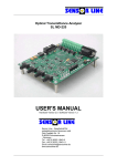
SL MD-220 Optical Transmittance Analyzer
Optical Transmittance Analyzer
SL MD-220
User’s Manual
Hardware Version 2.0 / Software Version 1.3
Measurement Specialties, Inc
1000 Lucas Way
Hampton, VA 23666
Tel.: 800 745 8008
Tel: +1 757 766 1500
Fax.:+1 767 766 4297
Email: [email protected]
www.meas-spec.com
SL MD-220 Optical Transmittance Analyzer
Sensor Line - Gesellschaft für
optoelektronische Sensoren mbH
Carl-Poellath-Str. 19
D-86259 Schrobenhausen
- Germany Tel.: +49 (0) 8252 / 8943-0
Fax.:+49 (0) 8252 / 8943-11
Email: [email protected]
www.sensorline.de
www.meas-spec.com
1/26
SUNSTAR自动化 http://www.sensor-ic.com/ TEL: 0755-83376489 FAX:0755-83376182 E-MAIL:[email protected]
09/15/2008
SUNSTAR传感与控制 http://www.sensor-ic.com/ TEL:0755-83376549 FAX:0755-83376182 E-MAIL:[email protected]
SL MD-220 Optical Transmittance Analyzer
Table of Contents
SL MD-220 ..............................................................................................................................................................1
1
General ............................................................................................................................................................4
1.1
1.2
1.3
2
Introduction ...............................................................................................................................................4
Principle of Operation ...............................................................................................................................4
Technical Data ..........................................................................................................................................6
Hardware Section ...........................................................................................................................................7
2.1
Dimensional Drawing ................................................................................................................................7
2.2
Handling Precautions................................................................................................................................7
2.3
Installation .................................................................................................................................................8
2.4
System Terminal .......................................................................................................................................8
2.4.1
Mechanical.........................................................................................................................................8
2.4.2
Connections .......................................................................................................................................8
2.4.2.1 Power Supply Terminal ..................................................................................................................8
2.4.2.2 Optocoupler Outputs ......................................................................................................................9
2.4.2.2.1 Internal Circuitry ........................................................................................................................9
2.4.2.2.2 External Wiring ..........................................................................................................................9
2.4.2.2.2.1 Generating Voltage Output Signals ...................................................................................9
2.4.2.2.2.2 Driving Loads...................................................................................................................10
2.5
RS-232 Interface .....................................................................................................................................11
2.5.1
Connector ........................................................................................................................................11
2.5.2
Wiring...............................................................................................................................................11
2.6
Reset Switch ...........................................................................................................................................12
2.7
8-Way SIL Switch....................................................................................................................................12
2.8
Jumpers ..................................................................................................................................................12
2.9
Status LEDs ............................................................................................................................................13
2.10 Measuring Pins .......................................................................................................................................13
2.11 Fiber Optic Receptacles..........................................................................................................................14
2.12 JTAG connector ......................................................................................................................................14
3
Software Section ..........................................................................................................................................15
3.1
General Description ................................................................................................................................15
3.2
Details .....................................................................................................................................................16
3.2.1
Startup Procedure............................................................................................................................16
3.2.2
Timing ..............................................................................................................................................17
3.2.2.1 Program cycle time ......................................................................................................................17
3.2.2.2 Watchdog Timer...........................................................................................................................17
3.2.3
Triggering.........................................................................................................................................17
3.2.3.1 Trigger Timing ..............................................................................................................................17
3.2.3.2 Nominal Trigger Threshold...........................................................................................................17
3.2.3.3 Adaptive Trigger Threshold..........................................................................................................18
3.2.4
SIL Switch and Jumper Settings......................................................................................................19
3.2.4.1 Switch Settings.............................................................................................................................19
3.2.4.2 Jumper Settings ...........................................................................................................................20
3.2.5
Status Outputs .................................................................................................................................20
3.2.5.1 Status LEDs .................................................................................................................................20
3.2.5.2 System Terminal Block ................................................................................................................20
3.2.5.3 Status Table .................................................................................................................................21
3.2.6
RS-232 Interface..............................................................................................................................22
3.2.6.1 General.........................................................................................................................................22
3.2.6.2 Comm Parameters .......................................................................................................................22
3.2.6.3 Output Modes...............................................................................................................................22
3.2.6.3.1 Voltage Mode ..........................................................................................................................22
SL MD-220 Optical Transmittance Analyzer
www.meas-spec.com
2/26
SUNSTAR自动化 http://www.sensor-ic.com/ TEL: 0755-83376489 FAX:0755-83376182 E-MAIL:[email protected]
09/15/2008
SUNSTAR传感与控制 http://www.sensor-ic.com/ TEL:0755-83376549 FAX:0755-83376182 E-MAIL:[email protected]
SL MD-220 Optical Transmittance Analyzer
3.2.6.3.2 Percent Mode ..........................................................................................................................23
3.2.6.3.3 Transmittance Mode................................................................................................................23
3.2.6.3.4 Status Mode ............................................................................................................................23
3.2.6.3.5 Off Mode..................................................................................................................................25
3.2.6.3.6 Software Version Query ..........................................................................................................25
3.2.6.3.7 Fast Mode ...............................................................................................................................25
3.2.6.3.8 Special Output Modes .............................................................................................................25
3.2.6.4 Commands ...................................................................................................................................25
3.2.6.4.1 System Reset Command ........................................................................................................25
3.2.6.4.2 Threshold Reset Commands ..................................................................................................26
SL MD-220 Optical Transmittance Analyzer
www.meas-spec.com
3/26
SUNSTAR自动化 http://www.sensor-ic.com/ TEL: 0755-83376489 FAX:0755-83376182 E-MAIL:[email protected]
09/15/2008
SUNSTAR传感与控制 http://www.sensor-ic.com/ TEL:0755-83376549 FAX:0755-83376182 E-MAIL:[email protected]
SL MD-220 Optical Transmittance Analyzer
1
General
1.1 Introduction
The SENSOR LINE MD-220 is a two-channel static opto-electronic interface for SENSOR LINE’s
SPZ/SPT fiber optic load sensors. This two-channel interface supplies light to two fiber optic sensors,
monitors the amount of light transmitted through the sensors and detects small changes caused by
loads applied to the sensors. With its advanced circuitry, the interface can detect a load on a sensor
for as long as it is applied to the sensor.
The MD-220 incorporates a TI MSP-430 embedded microcontroller, programmable via a JTAG
interface. It has a 10-wire screw-clip interface with power supply terminals and four floating
optocoupler outputs. It also has a RS-232 interface for input and output of data. Direct external
control is possible through the use of an 8-way SIL switch, two jumpers and a reset switch. For
quicker troubleshooting, six LED status displays show the function of the interface and there are five
easily accessible test points for analog measurements.
Power consumption has been minimized by circuitry that operates the transmitter diodes in series
while independently controlling the current through each diode. The MD-220 comes with two different
kinds of transmitter diodes, a near infrared diode giving each channel a dynamic range of 30 dB and a
more economic red diode for a dynamic range of 20 dB.
The hardware and software for the MD-220 come in different versions. This manual is divided into a
hardware and a software section.
Please ensure that you have the correct version of this manual.
1.2
Principle of Operation
A
MONx
D
7.5M
ANAx
I1
D
I2
A
A
470k
D
GND
GND
The drawing above is a simple circuit diagram of one channel. When the photodiode is illuminated
with light from the sensor it proportionally sinks a current to the incoming light power. This causes the
output of the OP to go high so the current is supplied across the 7.5M resistor. When the light
becomes too bright the OP output is clipped, and the controller supplies additional current via the
DAC and the 470k resistor until the OP output is “unclipped.”
SL MD-220 Optical Transmittance Analyzer
www.meas-spec.com
4/26
SUNSTAR自动化 http://www.sensor-ic.com/ TEL: 0755-83376489 FAX:0755-83376182 E-MAIL:[email protected]
09/15/2008
SUNSTAR传感与控制 http://www.sensor-ic.com/ TEL:0755-83376549 FAX:0755-83376182 E-MAIL:[email protected]
SL MD-220 Optical Transmittance Analyzer
Small changes of photo current are amplified by the OP by a factor of 7.5 MΩ (7.5 V/μA). The
controller measures this voltage ("Analog Voltage" or VANAx) as well as the voltage produced by the
DAC ("Monitor Voltage" or VMONx) with a resolution of 12 Bits. An additional DAC controls the light
power fed into the sensor.
Both voltages can be measured at test pins. Since the sensitivity of the photodiode is about 0.5 A/W
the incoming light power Φ can at any time be calculated using the formula
Φ
SL MD-220 Optical Transmittance Analyzer
W ⎛ VMONx VANAx ⎞
= 2 A · 470kΩ + 7.5MΩ
⎝
⎠
www.meas-spec.com
5/26
SUNSTAR自动化 http://www.sensor-ic.com/ TEL: 0755-83376489 FAX:0755-83376182 E-MAIL:[email protected]
09/15/2008
SUNSTAR传感与控制 http://www.sensor-ic.com/ TEL:0755-83376549 FAX:0755-83376182 E-MAIL:[email protected]
SL MD-220 Optical Transmittance Analyzer
1.3
Technical Data
Device Type:
Hardware Version:
Number of Channels:
Size:
Electrical Connections:
Optical connections:
LED Peak Output Wavelength
Maximum Sensor Loss:
Relative Humidity:
Temperature Range:
Supply Voltage:
Supply Current:
Analog Output at Test Points:
Optocoupler Outputs max.:
RS-232 connector
Velocity Range:
Feeder Length:
Comparative Laser Class:
EMV/EMI:
MD-220
Hardware
2.0c STD-1
2
100x110x19 mm (3.54x4.33x.75 in)
10-wire screw terminal block
RS-232, 3-wire**
5 test points
SMA 905
850 nm (NIR) / 660 nm (VIS red)
30 dB (NIR) / 20 dB (VIS)
80% at 25°C (77°F)
-40°C to 85°C (-40°F to 185°F)
+12 to +24 VDC
< 140 mA
0-10 V
OFF: 50V/<1uA
ON: 5V/50 mA (250 mW @ 25°C)
9-pin DSUB male
1 to 250 km/h (0.6 to 155 mph)
up to 250 meters (820ft)
3A (NIR, sensor disconnected)
Meets CE-requirements
Software
MD220STD
1.3
500 μs ± 5%
4 ms
0.2%, 0.4%, 0.8%, 1.6%
change of light transmittance**
Adaptive Threshold
0%, 6.25%, 12.5%, 25%, 50%
of load signal**
Hysteresis:
± 2 digits
Minimum input ON time:
3 program cycles (1.5 ms)
Minimum output ON time:
3 program cycles (1.5 ms) /
40 program cycles (20 ms)*
80 program cycles (40 ms)*
Maximum output ON time:
30 s
Baud Rate
9600 / 19200 / 115200 Bd**
Data Bits
8
Stop Bits
1
Parity
N (no parity)
Program Name:
Program Version:
Program cycle time:
Watchdog expiration time
Triggering Thresholds
RS-232
* selectable with jumper J1, ** selectable with SIL switch
SL MD-220 Optical Transmittance Analyzer
www.meas-spec.com
6/26
SUNSTAR自动化 http://www.sensor-ic.com/ TEL: 0755-83376489 FAX:0755-83376182 E-MAIL:[email protected]
09/15/2008
SUNSTAR传感与控制 http://www.sensor-ic.com/ TEL:0755-83376549 FAX:0755-83376182 E-MAIL:[email protected]
SL MD-220 Optical Transmittance Analyzer
2 Hardware Section
The PCB version is found on the bottom layer of the PCB. This manual is for hardware version 2.0.
2.1
Dimensional Drawing
Through Holes Ø3.1 (.122)
Transmitter 1
Channel 1
Transmitter
Transmitter 2
Channel 2
Transmitter
Receiver 2
Channel 2
Receiver
Test Points
RS-232
Connector
.
SIL-Switch
Status LEDs
+12..24VDC
GND
AUX2AUX2+
AUX1AUX1+
TRG2TRG2+
TRG1TRG1+
100 (3.937)
Fiber Optic SMA 905 Receptacles
90 (3.543)
Channel 1
Receiver
System Terminal
JTAG
Connector
Receiver 1
9 8 7 6 5 4 3 2 1 0
110 (4.331)
Jumpers
Reset
Switch
120 (4.724)
Maximum Height 19 (.748) - Dimensions in mm (in)
2.2 Handling Precautions
The MD-220 is delivered without a housing so handle it the same way as a PC card. Some of the
interface components are sensitive to electrostatic discharge (ESD). Leave the interface inside its
conductive bag until installation. Discharge yourself by touching a grounded conductor before
touching the interface. The receptacles are either non-conductive or grounded and the system
outputs have a special protective circuitry. It is relatively safe to handle the interface by these parts.
If conductive spacers are used, the interface may be handled by these spaces because the rims of
the through-holes are also grounded. Before pressing the reset switch by hand first discharge
yourself. The jumpers and LEDs are connected directly to the controller and should never be
touched. The test points are connected to OP outputs, which are also sensitive to ESD. Discharge
any measuring clips on the GND pin before contacting one of the other test points.
SL MD-220 Optical Transmittance Analyzer
www.meas-spec.com
7/26
SUNSTAR自动化 http://www.sensor-ic.com/ TEL: 0755-83376489 FAX:0755-83376182 E-MAIL:[email protected]
09/15/2008
SUNSTAR传感与控制 http://www.sensor-ic.com/ TEL:0755-83376549 FAX:0755-83376182 E-MAIL:[email protected]
SL MD-220 Optical Transmittance Analyzer
2.3 Installation
The MD-220 PCB has four Ø3.1mm (0.12”) through-holes, allowing it to be mounted on any
appropriate flat surface by means of M3 screws. At least 5mm (0.2”) spacers are recommended to
ensure a sufficient gap between the PCB and the mounting surface.
2.4
2.4.1
System Terminal
Mechanical
2
The system terminal is a 10-wire screw terminal block which accepts 0.14–1.5 mm (26–16 AWG)
wires. To fasten the screw clips a screwdriver with a blade up to 3.5 mm wide can be used. The
terminal block can either be a flat or angled design, the latter is used if several interfaces are stacked.
2.4.2
Connections
Pinning
Sign
+12...24VDC
GND
AUX2–
AUX2+
AUX1–
AUX1+
TRG2–
TRG2+
TRG1–
TRG1+
Description
}
}
}
}
Supply Voltage
Ground
Auxiliary Optocoupler Output 2
(Low Resistance = Sensor Failure)
Auxiliary Optocoupler Output 1
(Low Resistance = TRG1 AND TRG2)
Trigger Channel 2 Optocoupler Output
(Low Resistance = Load Response)
Trigger Channel 1 Optocoupler Output
(Low Resistance = Load Response)
2.4.2.1 Power Supply Terminal
Terminals 0 and 1 of the system terminal block are for connection of a 12-24 VDC power supply. The
MD-220 has built-in voltage regulators and is reverse voltage protected. The interface draws a
maximum of 140 mA. Connect the negative output to Terminal 1 and the positive output to
Terminal 0.
SL MD-220 Optical Transmittance Analyzer
www.meas-spec.com
8/26
SUNSTAR自动化 http://www.sensor-ic.com/ TEL: 0755-83376489 FAX:0755-83376182 E-MAIL:[email protected]
09/15/2008
SUNSTAR传感与控制 http://www.sensor-ic.com/ TEL:0755-83376549 FAX:0755-83376182 E-MAIL:[email protected]
SL MD-220 Optical Transmittance Analyzer
2.4.2.2 Optocoupler Outputs
2.4.2.2.1 Internal Circuitry
100 Ohms
+ Terminal
0.25W
H11G1
Optocoupler
68 V
– Terminal
The above schematic shows the internal circuitry of the TRG1 & 2 and AUX1 & 2 optocoupler outputs.
When the phototransistor is illuminated by the LED (ON condition) current flows into the + terminal
and out of the - terminal. The resistor limits the maximum allowable current to 50mA. Therefore, any
DC voltage applied directly to the outputs must not exceed 5V when the phototransistor is conductive
because the maximum power the 100 Ohm resistor can dissipate is 250mW.
When the phototransistor is not conductive the maximum voltage is limited by the zener diode to 68V.
If a voltage above that value is applied (even with additional resistors), the output might appear
conductive but the phototransistor is not. To avoid any glitches caused by voltage spikes or surges
the optocoupler outputs should not be operated with voltages above 50V.
2.4.2.2.2 External Wiring
The optocoupler outputs are not connected to any voltage source so there are many ways to obtain
various kinds of output signals. In all cases an external power supply must be added. The outputs
behave as switches with the restriction that current can only flow in one direction. Below are
examples of how the outputs may be wired.
2.4.2.2.2.1 Generating Voltage Output Signals
Voltage output signals are required if high impedance inputs, like those on an oscilloscopes, are
connected. The wiring from the diagrams below can be used if the voltage from the available source
has the required value or is not critical.
+ Terminal
10k
+
+
– Terminal
+ Vout
–
10k
+ Terminal
+ Vout
– Terminal
– Vout
–
– Vout
Zero output voltage going
HIGH on ON condition
SL MD-220 Optical Transmittance Analyzer
Positive output voltage going
LOW on ON condition
www.meas-spec.com
9/26
SUNSTAR自动化 http://www.sensor-ic.com/ TEL: 0755-83376489 FAX:0755-83376182 E-MAIL:[email protected]
09/15/2008
SUNSTAR传感与控制 http://www.sensor-ic.com/ TEL:0755-83376549 FAX:0755-83376182 E-MAIL:[email protected]
SL MD-220 Optical Transmittance Analyzer
If the voltage available is too high for the intended inputs a second resistor must be added in order to
create a voltage divider as given in the schematics below. It is generally safe to choose resistors in
the range of 10kΩ.
– Terminal
+
+
+ Terminal
+ Terminal
+ Vout
+ Vout
–
–
– Vout
– Terminal
– Vout
Positive output voltage going
LOW on ON condition
Zero output voltage going
HIGH on ON condition
2.4.2.2.2.2 Driving Loads
When there are no high impedance inputs that inhibit the flow of current it is not necessary to
generate a voltage. In this case the optocoupler output can be used as a switch to turn current on and
off. The wiring below shows how to operate an LED or drive optocoupler inputs or relays. The
current must be limited to a maximum of 50mA with an appropriate resistor.
R
+ Terminal
+
– Terminal
–
LED
Driving a LED
SL MD-220 Optical Transmittance Analyzer
www.meas-spec.com
10/26
SUNSTAR自动化 http://www.sensor-ic.com/ TEL: 0755-83376489 FAX:0755-83376182 E-MAIL:[email protected]
09/15/2008
SUNSTAR传感与控制 http://www.sensor-ic.com/ TEL:0755-83376549 FAX:0755-83376182 E-MAIL:[email protected]
SL MD-220 Optical Transmittance Analyzer
2.5 RS-232 Interface
The MD-220 has a three-wire RS-232 interface with a male 9-pin DSUB RS-232 connector. It
behaves like a PC, sending data on the TXD line (Pin 3) and receiving on the RXD line (Pin 2). It can
be connected directly to a printer with a standard RS-232 cable. To connect it to a PC a null-modem
cable is required, similar to the connection between two PCs. Please refer to the software section for
communication parameters as baud rate, parity, etc.
2.5.1
Connector
2.5.2
Wiring
MD-220
RS-232 device
5
9
4
8
3
7
2
6
1
GND
TXD
RXD
Female Connector
5
9
4
8
3
7
2
6
1
Male Connector
Standard RS-232 Cable
MD-220
PC
5
9
4
8
3
7
2
6
1
GND
Female Connector
1
6
2
7
3
8
4
9
5
Female Connector
Null-Modem Cable
SL MD-220 Optical Transmittance Analyzer
www.meas-spec.com
11/26
SUNSTAR自动化 http://www.sensor-ic.com/ TEL: 0755-83376489 FAX:0755-83376182 E-MAIL:[email protected]
09/15/2008
SUNSTAR传感与控制 http://www.sensor-ic.com/ TEL:0755-83376549 FAX:0755-83376182 E-MAIL:[email protected]
SL MD-220 Optical Transmittance Analyzer
2.6
Reset Switch
Pressing the reset switch causes a hardware reset of the microcontroller.
The two pads next to the right of the switch are connected in parallel and can accept a two-pin header
to allow for connection of an external switch.
2.7
8-Way SIL Switch
The SIL switch consists of eight individual switches which are connected to I/O pins of the
microcontroller. They are used to signal different conditions in order to modify the behavior of the
interface without re-programming it. Please refer to the software section of this manual for the
different switch settings.
2.8
Jumpers
SL MD-220 Optical Transmittance Analyzer
www.meas-spec.com
12/26
SUNSTAR自动化 http://www.sensor-ic.com/ TEL: 0755-83376489 FAX:0755-83376182 E-MAIL:[email protected]
09/15/2008
SUNSTAR传感与控制 http://www.sensor-ic.com/ TEL:0755-83376549 FAX:0755-83376182 E-MAIL:[email protected]
SL MD-220 Optical Transmittance Analyzer
The headers J1 and J2 can be used for the same purpose as the SIL switch (see above) by installing
jumpers or connecting external switches. They can also be used as I/O connections for various
purposes. Please refer to the software section of this manual for more information.
2.9
Status LEDs
There is a display of six LEDs controlled by the microcontroller. TRG1, TRG2, AUX1 and AUX2 are
yellow, and ERR1 and ERR2 are red. Please refer to the software section of this manual for the
meaning of the LED signals.
2.10 Measuring Pins
There are five test points with 1.3mm (0.05”) pins for measuring the analog voltages evaluated by the
microcontroller. The meaning of these voltages is thoroughly explained in paragraph 1.2 on page 4.
Label
Signal
Sign
GND
MON1
ANA1
MON2
ANA2
Ground
Monitor Voltage Channel 1
Analog Voltage Channel 1
Monitor Voltage Channel 2
Analog Voltage Channel 2
–
VMON1
VANA1
VMON2
VANA2
SL MD-220 Optical Transmittance Analyzer
www.meas-spec.com
13/26
SUNSTAR自动化 http://www.sensor-ic.com/ TEL: 0755-83376489 FAX:0755-83376182 E-MAIL:[email protected]
09/15/2008
SUNSTAR传感与控制 http://www.sensor-ic.com/ TEL:0755-83376549 FAX:0755-83376182 E-MAIL:[email protected]
SL MD-220 Optical Transmittance Analyzer
2.11 Fiber Optic Receptacles
Two fiber optic load sensors can be connected to the MD-220 via four SMA 905 fiber optic
receptacles. Viewed from the front the receptacles for Channel 1 are on the left hand side and those
for Channel 2 on the right hand side. The transmitters are the inner receptacles.
Do not stare into the transmitters when the interface is powered and there is no sensor
connected.
Fasten the sensor’s fiber connectors to the transmitter or receiver by screwing tightly on by hand (the
tighter, the smaller the attenuation). DO NOT USE PLIERS. The transmitter and receiver connectors
are interchangeable for each channel. The transmitter connectors are not interchangeable i.e. a
sensor connected for example to Transmitter 1 and Receiver 2 will not work.
2.12 JTAG connector
The JTAG connector is used for programming the microcontroller at the factory. If you are intending
to re-program the device in the field please contact Sensor Line GmbH for further information.
SL MD-220 Optical Transmittance Analyzer
www.meas-spec.com
14/26
SUNSTAR自动化 http://www.sensor-ic.com/ TEL: 0755-83376489 FAX:0755-83376182 E-MAIL:[email protected]
09/15/2008
SUNSTAR传感与控制 http://www.sensor-ic.com/ TEL:0755-83376549 FAX:0755-83376182 E-MAIL:[email protected]
SL MD-220 Optical Transmittance Analyzer
3 Software Section
The following refers to the MD-220 program MD220STD version 1.3.
3.1 General Description
The program executed by the microcontroller controls all functions of the MD-220. Detecting a load
applied to the sensor is difficult because of the large variation in sensor transmittance versus the
small amount of transmittance change when load is applied. For example, if the sensor transmittance
could change by a factor of 100 (20 dB) and the transmittance change caused by a load was 1%
(=1/100) the complete light measuring range would have to be resolved to 1/10000 of its value in
order to detect the load. This is more than twice the resolution of a 12-bit ADC.
To overcome this difficulty the microcontroller controls the photo currents detected by the input
amplifiers in two ways. First, it can vary the transmitter currents by a factor of ten. Second, it can
subtract an offset of up to 16 times the range of the amplifiers from their input current. With growing
sensor transmittance the light power fed into the sensors is reduced in order to avoid clipping of the
signal. When the minimum value is reached the controller compensates for further increases in
sensor transmittance by subtracting increasing portions of the photo current before the remainder is
fed into the amplifiers (see paragraph 1.2 on page 4).
After startup the program uses these methods to adjust the amplifiers' output voltages (called "analog
voltages") to a value in the upper region of the ADCs' measuring range. Then it establishes a
threshold below that value corresponding to a constant fraction of the light detected. After this
initialization process the program enters its main loop. Here it monitors the analog voltages and
checks if they have dropped below the threshold values, thus signaling load being applied to the
sensors.
As long as there is no load detected the thresholds are carefully adapted to slow changes (drifting) of
the detected light and the analog voltages are adjusted, if necessary. However, if there is load this
process cannot be continued since it is impossible to determine whether a change of the detected
light is due to drifting or due to a change of the load. As equipment does not stop drifting when there
is load on the sensor the interface cannot be allowed to detect load for infinite time. If during load
detection the amount of light detected without any load drifted below the stored threshold, the
interface would no longer be able to notice the load being removed; it would "hang".
For this reason there is a maximum detection time of 30 seconds. When this time has elapsed, the
interface performs an initialization process similar to the one at startup. The interface is then ready to
detect additional load being applied to the sensor. The original load effect is regarded as intrinsic
sensor attenuation. When the original load is removed the threshold is adapted immediately.
When the sensor is broken (or disconnected) no light arrives at the receiver and the interface is
unable to detect any load. If the sensor fails during operation, the detected light falls below the
threshold and is reported as load being detected. Therefore, sensor failure during operation is first
reported as a load detected, and it changes to an error signal after 30 seconds.
SL MD-220 Optical Transmittance Analyzer
www.meas-spec.com
15/26
SUNSTAR自动化 http://www.sensor-ic.com/ TEL: 0755-83376489 FAX:0755-83376182 E-MAIL:[email protected]
09/15/2008
SUNSTAR传感与控制 http://www.sensor-ic.com/ TEL:0755-83376549 FAX:0755-83376182 E-MAIL:[email protected]
SL MD-220 Optical Transmittance Analyzer
3.2
Details
3.2.1 Startup Procedure
After power-up or when a program reset is initiated the MD-220 first tries to adjust itself to the
particular sensors attached. This process takes about one second and is signaled by both ERRx
LEDs (see paragraph 3.2.5.1 on page 20) flashing at 8 Hz.
If insufficient light is detected, i.e. if there is no sensor connected to a channel or the connected
sensor is broken, the respective ERRx LED comes on continuously along with the AUX2 LED. The
AUX2 optocoupler output becomes conductive and the associated TRGx LED flashes ten times at 2
Hz. The TRGx LED is then switched off.
In the case that there is too much light detected (which may happen when an interface with infrared
transmitters is used in conjunction with a low loss sensor) the ERRx and AUX2 LEDs and the AUX2
optocoupler outputs behave the same way but the TRGx LED does not flash.
If the sensor loss is within a range where the interface can successfully adjust itself the program waits
for the transmitter to stabilize its output power. This is necessary because during power-up the
transmitter becomes warm, causing a slight decrease in its brightness during the first few seconds.
Since it is not possible to derive a measure for the sensor loss from the analog voltages at the test
pins, the interface signals the virtual sensor loss during warmup time. It cannot determine the real
sensor loss. Rather, the sensor loss, in this, cases, defines a certain value within an internal
"theoretic" dynamic range of 30 dB. For a number of reasons this range can not be fully utilized in
practice but the interface "sees" the loss of the sensors vary within it. In order to express this virtual
sensor loss the internal dynamic range is divided into ten intervals of 3 dB. While the transmitter is
warming up the TRGx LED of each channel is flashed from one to ten times. The number of times it
flashes multiplied by 3dB is the virtual sensor loss. If a sensor has high loss, the transmitter needs
more time to warm up because it is operated at high power.
The number of times the TRGx LEDs flash can not be directly translated into sensor loss since it is
given with respect to that particular channel's dynamic range. Dynamic range may vary due to
variations of the opto-electronic components. However, it shows how that particular sensor is
handled by that interface channel. If the TRGx LED flashes at least two times and no more than nine
times during the warmup time there is at least a 3 dB reserve and operation can generally be
considered to be safe, regardless of the exact sensor loss and the particular interface used.
As long as the sensor loss is signaled by flashing TRGx LEDs, the ERRx LEDs continue flashing at 8
Hz, showing the warmup time has not yet expired and the interface is not yet operational. After the
ERRx LEDs are switched off and the TRGx LEDs are continuously on the startup process is
complete.
SL MD-220 Optical Transmittance Analyzer
www.meas-spec.com
16/26
SUNSTAR自动化 http://www.sensor-ic.com/ TEL: 0755-83376489 FAX:0755-83376182 E-MAIL:[email protected]
09/15/2008
SUNSTAR传感与控制 http://www.sensor-ic.com/ TEL:0755-83376549 FAX:0755-83376182 E-MAIL:[email protected]
SL MD-220 Optical Transmittance Analyzer
3.2.2
Timing
3.2.2.1 Program cycle time
The main loop of the program is executed during a constant time interval of approximately 500 μs.
This time can vary about ± 5% due to the tolerance of the clock oscillator. All quantities are updated
at every cycle. The time resolution of the interface is therefore equal to the program cycle time.
3.2.2.2 Watchdog Timer
The watchdog timer is serviced every time the main loop is executed. Its time interval is set to 4 ms.
If the program hangs for whatever reason and this time expires a program reset is performed.
3.2.3
Triggering
3.2.3.1 Trigger Timing
The trigger function works with a threshold that has a hysteresis of only ± 2 digits. This is just
sufficient to prevent the interface from bouncing due to the sheer quantization error of the ADC.
Debouncing is done by requiring a valid load pulse to have at least 3 program cycles (1.5 ms) of
duration. This requires that the trigger delay also be 1.5 ms. The output pulse duration is correct
because switching off and on is subject to the same conditions.
Optionally the output pulse duration can be forced to a certain minimum value, regardless of the input
pulse duration. The output will then be on for at least that minimum time (20 ms or 40 ms in this
program version). Otherwise the output pulse duration can become as short as 1.5 ms. Please refer
to section 3.2.4 on how to define the minimum output pulse duration.
The maximum output pulse duration is 30 s. This is the maximum detection time explained in
paragraph 3.1. After 30s the interface is freshly adjusted and ready to detect a new load.
3.2.3.2 Nominal Trigger Threshold
Before introduction of hardware version 2.0 the trigger threshold was a fixed value and adjustment
required re-programming. MD220STD v1.3 allows to select threshold values of 0.2%, 0.4%, 0.8% and
1.6% change of light transmittance. Please refer to section 3.2.4 for instructions.
SL MD-220 Optical Transmittance Analyzer
www.meas-spec.com
17/26
SUNSTAR自动化 http://www.sensor-ic.com/ TEL: 0755-83376489 FAX:0755-83376182 E-MAIL:[email protected]
09/15/2008
SUNSTAR传感与控制 http://www.sensor-ic.com/ TEL:0755-83376549 FAX:0755-83376182 E-MAIL:[email protected]
SL MD-220 Optical Transmittance Analyzer
3.2.3.3 Adaptive Trigger Threshold
Adaptive threshold processing is a trigger algorithm introduced with Version 1.3 of MD220STD. It is
intended to be applied in cases where sensors show a noticeably delayed relaxation process.
Behaviour of this kind can encumber certain signal processing methods for dual-tire detection or
automatic vehicle classification which rely on correct registration of the load pulse duration. In
extreme cases it can even cause the trigger output to "hang" after a tire has left the sensor.
This issue is overcome by the adaptive threshold algorithm: After the trigger event has happened the
trigger threshold follows the sensor signal with a certain fraction of its amplitude as long as the
amplitude is growing, i.e. the sensor transmittance is decreasing. When the sensor transmittance
rises the threshold is held constant until the trigger state has switched to OFF again. After that the
threshold is held at a level below the sensor signal which complies to the nominal threshold value
according to section 3.2.3.2 as long as the sensor transmittance is not decreasing again.
Adaptive Threshold
Fixed Threshold
Trigger Output State
Sensor Transmittance
100%
Sensor Signal
ON
Output Pulse
with Adaptive
Threshold
Output Pulse
with Fixed
Threshold
OFF
Time
Adaptive threshold processing can be switched on and off. The ratio of signal amplitude to which the
trigger threshold adapts can be defined to values of 50%, 25%, 12.5% and 6.25%. Please refer to
section 3.2.4 for instructions.
SL MD-220 Optical Transmittance Analyzer
www.meas-spec.com
18/26
SUNSTAR自动化 http://www.sensor-ic.com/ TEL: 0755-83376489 FAX:0755-83376182 E-MAIL:[email protected]
09/15/2008
SUNSTAR传感与控制 http://www.sensor-ic.com/ TEL:0755-83376549 FAX:0755-83376182 E-MAIL:[email protected]
SL MD-220 Optical Transmittance Analyzer
3.2.4
SIL Switch and Jumper Settings
3.2.4.1 Switch Settings
Both boards have an 8-way SIL switch immediately behind the display LEDs. The particular switches
are numbered from 1 to 8 where switch 1 is the leftmost one. They are in on-position when swiveled
towards the front edge of the board i.e. towards the LEDs. Factory setting is all switches off.
7
8
Enforce Minimum
Pulse Duration
Adaptive Threshold
LO
6
High Speed
Enable
Adaptive Threshold
HI
4
Baudrate
Select
3
5
Trigger Threshold
LO
2
Trigger Threshold
HI
1
Adaptive Threshold
Enable
Switch Functions:
Switches 1-3 set the percentage to which the trigger off threshold follows an input pulse (adaptive
threshold, see section 3.2.3.3):
Way1
off
ON
ON
ON
ON
Way2
X
off
off
ON
ON
Way3
X
off
ON
off
ON
Percentage
0%
6.25%
12.5%
25%
50%
Switches 4 and 5 define the nominal trigger on threshold (see section 3.2.3.2):
Way4
off
off
ON
ON
Way5
off
ON
off
ON
Threshold
0.8%
1.6%
0.2%
0.4%
Switches 6 and 7 select the baud rate of the serial interface (see section 3.2.6.2):
Way6
off
ON
X
Way7
off
off
ON
Baud
9600
19200
115200
When Switch 8 is in ON position the trigger output on time is forced to a minimum value which
depends from the setting of Jumper J1 (see below).
SL MD-220 Optical Transmittance Analyzer
www.meas-spec.com
19/26
SUNSTAR自动化 http://www.sensor-ic.com/ TEL: 0755-83376489 FAX:0755-83376182 E-MAIL:[email protected]
09/15/2008
SUNSTAR传感与控制 http://www.sensor-ic.com/ TEL:0755-83376549 FAX:0755-83376182 E-MAIL:[email protected]
SL MD-220 Optical Transmittance Analyzer
3.2.4.2 Jumper Settings
When Jumper J1 is installed, the minimum trigger output on time is 40 ms, with J1 removed it is
20 ms. This requires Switch 8 to be set to ON position (see above), otherwise the configuration of J1
has no effect.
Jumper J2 is reserved for future use.
3.2.5 Status Outputs
The status outputs are the six status LEDs and four optocoupler outputs on the system terminal block.
In spite of the common labeling of some of them their behavior is not the same. This might be
confusing at first but provides maximum convenience during operation.
3.2.5.1 Status LEDs
There are three groups of status LEDs: TRGx, AUXx and ERRx. The TRGx LEDs show the trigger
status of both channels, the red ERRx LEDs report error conditions and the AUXx show other
conditions or events.
The TRGx LEDs correspond to one channel each. During initialization when the interface is adjusting
itself they are flashing up to ten times, giving a measure of the sensor loss (see also paragraph 3.2.1
on page 16). They are on if the respective channel is ready to detect load and go off when load a
load is detected or when an error occurs.
The ERRx LEDs are also associated to one channel each. During initialization they are flashing. If
the controller cannot transmit enough light through a sensor the respective ERR LED is switched on
continuously.
The AUX1 LED is on when both channels are detecting load, otherwise it is off.
The AUX2 LED comes on when either of the channels has an error condition and its ERR LED is on
continuously. This might seem redundant, but the AUX2 LED is switched on and off in accordance with the
AUX2 optocoupler output which reports an error (see below). This is convenient for troubleshooting purposes.
3.2.5.2 System Terminal Block
The system terminal block has four optocoupler outputs, divided into two groups: TRGx and AUXx.
The TRGx outputs become conductive (ON condition) when there is load detected by the respective
channel. This is inverse to the TRGx LEDs!
The AUXx optocoupler outputs follow the AUXx LEDs. The AUX1 output comes on when both of the
TRGx outputs are on and the AUX2 output comes on when there is an error condition regardless at
what channel.
SL MD-220 Optical Transmittance Analyzer
www.meas-spec.com
20/26
SUNSTAR自动化 http://www.sensor-ic.com/ TEL: 0755-83376489 FAX:0755-83376182 E-MAIL:[email protected]
09/15/2008
SUNSTAR传感与控制 http://www.sensor-ic.com/ TEL:0755-83376549 FAX:0755-83376182 E-MAIL:[email protected]
SL MD-220 Optical Transmittance Analyzer
3.2.5.3 Status Table
The table below is to summarize the different states the two channels can be in and the according
behavior of the status outputs.
Status
Channel 1
Channel 2
adjust
Adjust
adjust
Ready
adjust
Detect
adjust
Error
ready
Adjust
ready
Ready
ready
Detect
ready
Error
detect
Adjust
detect
Ready
detect
Detect
detect
Error
error
Adjust
error
Ready
error
Detect
error
Error
Status LEDs
TRG1 TRG2 AUX1 AUX2 ERR1 ERR2
flash flash
*
*
flash
*
ON
flash
*
flash
*
ON
ON
flash
ON
*
ON
ON
ON
ON
ON
ON
flash
*
ON
ON
ON
ON
flash
*
ON
ON
ON
ON
ON
ON
ON
ON
ON
ON
Optocoupler Outputs
TRG1 TRG2 AUX1 AUX2
ON
ON
ON
ON
ON
ON
ON
ON
ON
ON
ON
ON
ON
ON
ON
ON
* : may flash during startup
SL MD-220 Optical Transmittance Analyzer
www.meas-spec.com
21/26
SUNSTAR自动化 http://www.sensor-ic.com/ TEL: 0755-83376489 FAX:0755-83376182 E-MAIL:[email protected]
09/15/2008
SUNSTAR传感与控制 http://www.sensor-ic.com/ TEL:0755-83376549 FAX:0755-83376182 E-MAIL:[email protected]
SL MD-220 Optical Transmittance Analyzer
3.2.6
RS-232 Interface
3.2.6.1 General
The RS-232 interface of the MD-220 allows bi-directional communication with a host computer or a
passive RS-232 device. It can be used for debugging and troubleshooting purposes as well as for
setting up simple measuring systems. Please refer to paragraph 2.5 for the wiring of the connector.
3.2.6.2 Comm Parameters
The baud rate of the MD-220's RS-232 interface is adjustable to 9600, 19200 and 115200 Baud. The
remaining parameters are 8,N,1 (8 data bits, 1 stop bit, no parity).
The higher baud rates may not be available especially with older RS-232 PC interfaces. However,
with an USB-to-RS232 adapter they should work without problems.
3.2.6.3 Output Modes
There are several different possibilities to output useful data via RS-232. Switching between these
output modes is done by sending single characters to the MD-220. The easiest way to do so is by
using the keyboard on a PC running a terminal program.
3.2.6.3.1 Voltage Mode
The Voltage Mode is the default mode at startup. While operating in another mode, the MD-220
enters the Voltage Mode when it receives a "v" or a "V". The interface then continuously reports its
analog voltages, monitor voltages and thresholds. The message format is
Line Feed (0Ah)
Carriage Return (0Dh)
Channel 2
Monitor Voltage
3 digits hex
X X X CR LF
blank (20h)
Channel 2
Trigger Threshold
3 digits hex
X X X
blank (20h)
Channel 2
Analog Voltage
3 digits hex
X X X
blank (20h)
Channel 1
Monitor Voltage
3 digits hex
X X X
blank (20h)
Channel 1
Trigger Threshold,
3 digits hex
X X X
blank (20h)
Channel 1
Analog Votage,
3 digits hex
X X X
All voltages are given in 12 bits ADC digits with a maximum value of FFFh (=4095) corresponding to a
voltage of approximately 10V.
This output can be logged and later processed into suitable diagrams. When reading it into Microsoft
EXCEL all fields must explicitly be marked as text format, otherwise numbers that do not contain any
letters will be imported as decimal numbers.
SL MD-220 Optical Transmittance Analyzer
www.meas-spec.com
22/26
SUNSTAR自动化 http://www.sensor-ic.com/ TEL: 0755-83376489 FAX:0755-83376182 E-MAIL:[email protected]
09/15/2008
SUNSTAR传感与控制 http://www.sensor-ic.com/ TEL:0755-83376549 FAX:0755-83376182 E-MAIL:[email protected]
SL MD-220 Optical Transmittance Analyzer
3.2.6.3.2 Percent Mode
Percent mode is entered as soon as the MD-220 receives a "p" or a "P". It continuously reports the
relative difference of the registered light power to that which is related to the currently established
trigger threshold. The message format is
Line Feed (0Ah)
Carriage Return (0Dh)
Channel 2
Relative Signal
3 digits hex
Sign ("+" or "–")
+ X X X CR LF
blank (20h)
Channel 1
Relative Signal
3 digits hex
Sign ("+" or "–")
+ X X X
The values are given in units of 0.1%. For example if the trigger threshold is set to 0.8% the values
issued should be around "+008". As soon as the sign changes to "–" the interface will trigger.
This output mode allows for quick judgment of the measuring effect – especially the quality of the
sensor setup – on-site without any computations. The signal resolution is significantly lower than that
obtained from voltage data, but the messages are shorter so there is a higher time resolution in
percent mode.
3.2.6.3.3 Transmittance Mode
With this output mode a host computer checks the loss of connected sensors. This cannot be derived
from the analog and monitor voltages alone because these do not contain any information about the
light power fed into the sensors. When a "t" or a "T" is received the MD-220 continuously reports the
sensor transmittances with two four-digit hex numbers every line. The message format is
Line Feed (0Ah)
Carriage Return (0Dh)
Channel 2
Transmittance
4 digits hex
X X X X CR LF
blank (20h)
Channel 1
Transmittance
4 digits hex
X X X X
Unlike the logarithmic sensor loss which is given in dB and signaled by the TRGx LEDs on startup the
sensor transmittance is a linear quantity which is given in arbitrary units here. The theoretic dynamic
range of the interface is represented by values from 4h (4) to D8Fh (3471). It must be noted that
errors are not signaled exactly when these values are exceeded because the conditions which define
an error are not derived from this quantity.
3.2.6.3.4 Status Mode
SL MD-220 Optical Transmittance Analyzer
www.meas-spec.com
23/26
SUNSTAR自动化 http://www.sensor-ic.com/ TEL: 0755-83376489 FAX:0755-83376182 E-MAIL:[email protected]
09/15/2008
SUNSTAR传感与控制 http://www.sensor-ic.com/ TEL:0755-83376549 FAX:0755-83376182 E-MAIL:[email protected]
SL MD-220 Optical Transmittance Analyzer
This is a non-continuous output mode. It is entered on receipt of an "s" or an "S". The status of each
channel of the MD-220 is internally described by two status bytes. Every time one of these four bytes
changes a status message is issued. The message format is
Line Feed (0Ah)
Carriage Return (0Dh)
Channel 2
Status
4 digits hex
X X X X CR LF
blank (20h)
Channel 1
Status
4 digits hex
X X X X
blank (20h)
Millisecond count
3 digits hex
X X X
blank (20h)
Second count
3 digits hex
X X X
The first 3-digit hex number gives the number of seconds elapsed since the last reset. It is reset to
zero every hour (its maximum value is E0Fh (=3599)). The second number is the number of
milliseconds which is zeroed when the second count changes. Its maximum value is therefore 3E7h
(=999).
The following two 4-digit hex numbers give bit-wise information about the status of each channel.
Their meaning is as follows:
Bit 0 / LSB
Bit 1
TRIGGERED
TRG_TIMEOUT
Bit 2
Bit 3
Bit 4
Bit 5
Bit 6
Bit 7
Bit 8
TRG_INHIBIT
ANALOG_LOW
ANALOG_HIGH
ANALOG_DOWN
ANALOG_CLIPPED
THRSH_NOUPDATE
Bit 9
THRSH_TIMEOUT
Bit 10
THRSH_RESET
Bit 11
THRSH_NINIT
Bit 12
SENSOR_HIGHLOSS
Bit 13
SENSOR_LOWLOSS
Bit 14
Bit 15 / MSB
Channel is currently detecting load, trigger signal is on
Trigger signal has been on for 30 s and will now be cleared,
trigger threshold will be reset
Trigger signal inhibited
reserved
ANAx voltage requires upward adjustment
ANAx voltage requires downward adjustment
ANAx voltage too low for proper triggering – Error
ANAx voltage too high for proper triggering – Error
Updating of trigger threshold is inhibited due to expected
load detection
Trigger threshold has not been updated for 30 s and will be
updated now
Trigger threshold is considered to be wrong and will
immediately be set to 0.2%, 0.4%, 0.8%, 1.6% below current
light level
Trigger threshold not initialized, trigger signal inhibited
Sensor loss above dynamic range – Error
Sensor loss below dynamic range – Error
reserved
reserved
The very first status message is transmitted immediately after entering status mode but this does not
mean that something has changed at that moment. Every additional "s" or "S" triggers a new
message without status change.
SL MD-220 Optical Transmittance Analyzer
www.meas-spec.com
24/26
SUNSTAR自动化 http://www.sensor-ic.com/ TEL: 0755-83376489 FAX:0755-83376182 E-MAIL:[email protected]
09/15/2008
SUNSTAR传感与控制 http://www.sensor-ic.com/ TEL:0755-83376549 FAX:0755-83376182 E-MAIL:[email protected]
SL MD-220 Optical Transmittance Analyzer
3.2.6.3.5 Off Mode
On receipt of an "o", an "O" or a "0" (zero) the transmission of any messages is inhibited. The
interface still receives characters and can be switched to another mode at any time.
3.2.6.3.6 Software Version Query
When the MD-220 receives a "q" or a "Q" a short copyright notice including name and version number
of the loaded software is issued. Enter off mode or status mode before querying the software version.
3.2.6.3.7 Fast Mode
Fast Mode was formerly one of the special output modes addressed in section 3.2.6.3.8. Since it has
repeatedly been applied in the field some more detailed discussion is adequate.
The MD-220 enters Fast Mode on receipt of a capital 'F'. This is a continuous output mode where the
analog voltage readings (see section 1.2) of both channels are converted into strings of two printable
characters each and transmitted without any delimiter. Every 76 characters a CRLF sequence is
inserted, mainly for the purpose of synchronization but also to facilitate display with terminal
programs. By this a very high repetition rate is obtained which is necessary to resolve sensor signals
also with faster moving traffic.
The algorithm which converts the signal values to printable characters is derived from the common
"uuencode" algorithm but not compatible, so special software is needed to decode the output.
When working with Fast Mode two things must be considered:
First, the values of the monitor voltage and the trigger threshold are not transmitted as they are in
Voltage Mode. This yields some much higher measuring frequency, but without knowledge of these
quantities neither computation of the relative sensor signal nor deduction of the trigger signal is
possible. So if Fast Mode data are to be of any value they must be accompanied by a short sequence
of Voltage Mode messages captured under the same circumstances (without traffic).
Second, due to the high measuring rate the amount of accumulating data grows very fast. Fast Mode
is therefore absolutely inadequate for any kind of long term logging purposes. Its output can only be
processed without major problems if it consists of short sequences; it is virtually impossible to isolate
interesting events from megabytes of logged traffic. So the best way to utilize Fast Mode is first
capturing some lines in Voltage Mode, then switching to Off Mode, invoking Fast Mode immediately
before an interesting event, and immediately afterwards shutting it down again.
3.2.6.3.8 Special Output Modes
When one of the characters 'C', 'Y' or Ctrl-q (Chr$(17)) is received the interface enters special output
modes which are meant for laboratory use or troubleshooting in special cases. The output consists
entirely of printable characters, but special software is required to decode it.
3.2.6.4 Commands
Aside from the previously described characters which only change the output sent via the RS-232
interface there are also characters which directly affect the behavior of the MD-220.
3.2.6.4.1 System Reset Command
On receipt of a capital 'R' a software reset is initiated just as if the reset button had been pressed.
This is done by sending the controller into a non-terminated loop and having the watchdog timer
SL MD-220 Optical Transmittance Analyzer
www.meas-spec.com
25/26
SUNSTAR自动化 http://www.sensor-ic.com/ TEL: 0755-83376489 FAX:0755-83376182 E-MAIL:[email protected]
09/15/2008
SUNSTAR传感与控制 http://www.sensor-ic.com/ TEL:0755-83376549 FAX:0755-83376182 E-MAIL:[email protected]
SL MD-220 Optical Transmittance Analyzer
trigger the reset. Consequently, it may take up to 4 ms until it is executed. This command can also be
used to verify the watchdog function.
3.2.6.4.2 Threshold Reset Commands
When the MD-220 receives a '1' or a '2' the trigger threshold of the respective channel is immediately
reset. This must not be confused with a system reset which causes the complete startup initialization
process to be performed. Here the interface only accepts the current light level as new no-load value
and establishes its trigger threshold 0.2%, 0.4%, 0.8%, 1.6% below it.
The threshold management algorithm used with MD220STD v1.3 is sophisticated. This can not keep
the interface from hanging if during load detection something reduces the sensor's transmittance
permanently. The trigger signal will then remain on for 30 s and the interface will be unable to detect
any new load cycle during this time.
The threshold reset command enables a host computer to tell the MD-220 that there is currently no
load on the sensor. This is useful to clear the trigger signal in situations where the interface is
suspected or known to be hanging. The command can also be given by the host computer if it knows
there can be no load on the sensor from another detector (i.e. a inductive loop). Using this feature will
make malfunctions or anomalies virtually impossible.
The command should not be used to acknowledge a trigger signal by clearing it since the load may
not have reached its maximum value yet. If the trigger threshold is reset while the load increases a
second trigger signal might be erroneously generated by the still increasing load.
Important notice
All the information contained herein is believed to be accurate and reliable. However, SENSOR LINE assumes no responsibility for its use
or for any infringements of patents or other rights of third parties that may result from its use. No license is granted by implication or
otherwise under any patent rights of SENSOR LINE GmbH.
SENSORLINE shall not be liable for any special, incidental or consequential damages related to the use of the product.
Our product guides and instructions are continuously updated. Make sure you have got the latest edition. For further information contact the
SENSOR LINE technical support team.
SL MD-220 Optical Transmittance Analyzer
www.meas-spec.com
26/26
SUNSTAR自动化 http://www.sensor-ic.com/ TEL: 0755-83376489 FAX:0755-83376182 E-MAIL:[email protected]
09/15/2008