1
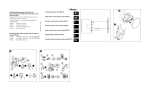
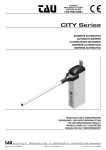
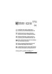
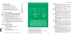
XP15W XP 15 W 37 mm. 26 TX m m 105 mm. . + Fig. 1 _ RX Fig. 4 RX 햲 Ø16 mm. Max Fig. 2 RX NC + COM ~ _ Fig. 5 TX 햲 mm. Ø16 Max _ + ~ Fig. 3 1 Fig. 6 RX TX P1 DL2 Fig. 7 RX TX DL2 DL2 DL3 DL1 DL1 Fig. 8 Fig. 9 2 1. DESCRIZIONE E CARATTERISTICHE TECNICHE ................................................................................. p. 4 2. DIMENSIONI .................................................................................................................................. p. 4 3. INSTALLAZIONE p. 4 ............................................................................................................................ 4. COLLEGAMENTI ELETTRICI .............................................................................................................. p. 4 5. MESSA IN FUNZIONE ...................................................................................................................... p. 4 6. RICERCA GUASTI ........................................................................................................................... p. 5 DICHIARAZIONE CE DI CONFORMITÁ Fabbricante: Indirizzo: Dichiara che: FAAC S.p.A. Via Benini, 1 - 40069 Zola Predosa BOLOGNA - ITALIA Il dispositivo di protezione attiva opto-elettronico mod. XP 15 W, •è conforme ai requisiti essenziali di sicurezza delle seguenti direttive CEE: 2006/95/CE Direttiva Bassa Tensione 2004/108/CE Direttiva Compatibilità Elettromagnetica Nota aggiuntiva: Questo prodotto è stato sottoposto a test in una configurazione tipica omogenea (tutti prodotti di costruzione FAAC S.p.A.) Bologna, 01 Maggio 2008. L’AmministratoreDelegato A. Bassi AVVERTENZE •Attenzione! È importante per la sicurezza delle persone seguire attentamente tutta l’istruzione. •Una errata installazione o un errato uso del prodotto può portare a gravi danni alle persone. •Leggere attentamente le istruzioni prima di iniziare l’installazione del prodotto e conservarle per riferimenti futuri. Leggere completamente questo manuale di istruzioni prima di iniziare l’installazione del prodotto. Il simbolo Il simbolo evidenzia le note importanti per la sicurezza delle persone e l’integrità dell’automazione. richiama l’attenzione sulle note riguardanti le caratteristiche od il funzionamento del prodotto. FAAC S.p.A. Via Benini, 1 40069 Zola Predosa (BO) - ITALIA Tel.: 051/61724 - Fax: 051/758518 www.faac.it 732563 Rev. A 3 ITALIANO Indice ITALIANO XP 15 W Il Trasmettitore della coppia XP15 W ha la possibilità di essere alimentato tramite la batteria interna (Fig. 4) oppure tramite collegamento filare. Il Trasmettitore alimentato a batteria necessita del solo fissaggio a parete o su colonnetta. 1. DESCRIZIONE E CARATTERISTICHE TECNICHE La coppia di fotocellule autoallineanti XP15 W è composta da un trasmettitore ed un ricevitore a raggi infrarossi sincronizzati a quattro canali selezionabili. La fotocellula XP15 W è un dispositivo ausiliario alla sicurezza. L’oscuramento del fascio luminoso, provoca il cambiamento di stato del ricevitore, il quale invia il segnale di fotocellula impegnata tramite contatto a relè. Il Trasmettitore della coppia è alimentato a batteria ma può anche essere alimentato tramite il collegamento filare. La selezione del canale di trasmissione permette di installare sullo stesso impianto fino a 4 coppie di XP15 W eliminado il rischio di interferenze tra una coppia e l’altra. ALIMENTAZIONE ASSORBIMENTO RX 4. COLLEGAMENTI ELETTRICI Eseguire i collegamenti elettrici sulle morsettiere del ricevitore come indicato in Fig. 5. I morsetti di alimentazione del Ricevitore possono essere collegati ad una tensione di 12 o 24 Volt sia continua (DC) che alternata ( ~ ). 12 - 24 V~. 12 - 24 Vdc Qualora si intenda effettuare il controllo FAIL SAFE con Trasmettitore alimentato a batteria, collegare il morsetto FAIL SAFE (-TX FSW) delle schede _ elettroniche FAAC al morsetto MENO ( ) del Ricevitore fotocellula. 30 mA TIPO E DURATA BATTERIA TX 40 A a Batteria 5 mA a 24 Vdc CR2 DA 3 V da 2 a 3 anni * PORTATA MASSIMA 15 m GRADO DI PROTEZIONE IP54 TEMPO RILEVAMENTO OSTACOLO MODALITÀ DI ALLINEAMENTO 40 ms automatica ANGOLO DI AUTOALLINEAMENTO +/- 7° (15 m) +/- 13° (5 m.) TRAMISSIONE SEGNALE 4 canali selezionabili TEMPERATURA DI FUNZIONAMENTO -20...+55 °C INSTALLAZIONE a parete o su colonnetta ASSORBIMENTO TX Qualora il Trasmettitore utilizzi l’alimentazione filare, seguire le stesse tipologie d’installazione indicate nelle figure 2 e 3. Nel caso si alimenti il Trasmettitore tramite collegamento filare seguire le indicazioni in Fig. 6. I morsetti di alimentazione del Trasmettitore possono essere collegati ad una tensione di 12 o 24 Volt sia continua (DC) che alternata ( ~ ). All’accensione del Trasmettitore e del Ricevitore i rispettivi led DL2 si accendono per 1 secondo. 5. MESSA IN FUNZIONE Prima di chiudere la coppia di fotocellule con i rispettivi coperchi, è indispensabile selezionare il canale di trasmissione e controllarne il funzionamento attraverso i LED di segnalazione presenti sul Ricevitore. SELEZIONE CANALE DI TRASMISSIONE Alimentare le fotocellule e selezionare il canale di trasmissione PREMENDO E MANTENEDO PREMUTO PER 5 SECONDI il pulsante P1 (fig.7). Al termine dei 5 secondi il led DL2 in figura 7 lampeggerà un numero di volte pari al canale impostato per poi spegnersi 1 secondo e ripetere la segnalazione. Dopo aver completato 3 segnalazioni del canale impostato la procedura è terminata ed il canale è memorizzato. Durante questa visualizzazione è possibile cambiare il canale di trasmissione: tramite la pressione del pulsante P1 si selezionano in successione i quattro canali. Controllare il numero di lampeggi del led DL2 per determinare quale canale si è selezionato: 1 lampeggio = Canale 1 2 lampeggi = Canale 2 3 lampeggi = Canale 3 4 lampeggi = Canale 4 * La durata della batteria può variare in funzione della carica della batteria impiegata, della sua tipologia e delle condizioni ambientali/installative. 2. DIMENSIONI Le dimensioni del Trasmettitore e del Ricevitore sono le medesime e sono riportate in Figura 1. 3. INSTALLAZIONE Per un corretto funzionamento, posizionare il Ricevitore e il Trasmettitore allineati. Il Ricevitore della coppia XP15 W ha due possibili tipologie d’installazione: - A parete con guaina ad incasso (Fig. 2). - A parete con tubo/guaina esterni (Fig. 3). •Eseguire le predisposizioni per i collegamenti elettrici. •Fissare il corpo del ricevitore utilizzando viti e tasselli idonei. Impostare lo stesso canale sia sul ricevitore che sul trasmettitore. 4 Di seguito sono riportati gli stati ed il significato dei led a bordo del Trasmettitore; fare riferimento alla figura 9 per individuarne la posizione. CONTROLLO DEI LED DI SEGNALAZIONE RX DL 1 Di seguito sono riportati gli stati ed il significato dei led a bordo del Ricevitore; fare riferimento alla figura 8 per individuarne la posizione. ON Alimentazione filare presente OFF Alimentazione filare assente, funzionamento a batteria DL 1 Alimentazione ON Alimentazione presente OFF Alimentazione assente DL 2 DL 2 OFF Normale Funzionamento Canale di Trasmissione e Carica Batteria TX Batteria TX OK Lampeggio Lento Indicazione canale di trasmissione Lampeggio Veloce Batteria TX in esaurimento OFF Batteria TX scarica o Fotocellula impegnata ON Canale di Trasmissione Lampeggio Visualizzazione del canale di trasmissione Lento ON DL 3 Alimentazione Completare l’installazione chiudendo le fotocellule appena installate con l’apposito coperchio a quattro viti, avendo cura di posizionare il separatore in gomma (indicato in fig. 2, 3 rif. 햲 ) così da garantire il corretto grado di isolamento IP. Allineamento Allineamento OK Lampeggio Allineamento non corretto Lento OFF Allineamento assente o Fotocellula impegnata 6. RICERCA GUASTI Di seguito è riportato un aiuto per l’individuazione e la risoluzione di particolari condizioni sul funzionamento delle fotocellule. Per una lista completa delle situazioni di errore/guasto fare riferimento all’istruzione dell’apparecchiatura elettronica utilizzata per movimentare l’applicazione. CONDIZIONE CAUSA/PROBLEMA SUGGERIMENTO Il cancello non si muove. i led DL2 e DL3 del Ricevitore sono spenti. - Mancanza di allineamento - Trasmettitore non alimentato - Errata scelta del canale di trasmissione. - Controllare la selezione del canale di trasmissione. - Controllare l’alimentazione degli elementi della coppia di fotocellulle. - Controllare l’allineamento della coppia. Il led DL2 del Ricevitore lampeggia. Alimentazione del Trasmettitore non corretta. - Sostituire la batteria interna del Trasmettitore. - In caso di alimentazione filare del Trasmettitore controllarne il valore di tensione. Il led DL3 del Ricevitore lampeggia. Le fotocellule non sono correttamente allineate. - Regolare l’allineamento delle fotocellule. 5 ITALIANO CONTROLLO DEI LED DI SEGNALAZIONE TX Durante la visualizzazione del canale impostato la coppia di fotocellule è inattiva ed il suo contatto è quindi APERTO. Attendere il termine della visualizzazione per operare con l’automazione. ENGLISH Index 1. DESCRIPTION AND TECHNICAL SPECIFICATIONS ............................................................................. p. 7 2. DIMENSIONS .................................................................................................................................. p. 7 3. INSTALLATION p. 7 ............................................................................................................................... 4. ELECTRICAL CONNECTIONS .......................................................................................................... p. 7 5. START-UP ........................................................................................................................................ p. 7 6. TROUBLESHOOTING p. 8 ...................................................................................................................... CE DECLARATION OF CONFORMITY Manufacturer: Address: Declares that: FAAC S.p.A. Via Benini, 1 - 40069 Zola Predosa BOLOGNA - ITALY The opto-electronic active protection device mod. XP 15 W, •conforms to the essential safety requirements of the following EEC directives: 2006/95/EC Low Voltage Directive 2004/108/EC Electromagnetic Compatibility Directive Additional information: This product underwent a test in a typical, uniform configuration (all products made by FAAC S.p.A) Bologna, 01 May 2008. The Managing Director A. Bassi WARNINGS •Important! For the safety of people, it is important that all the instructions be carefully observed •Incorrect installation or incorrect use of the product could cause serious harm to people. •Carefully read the instructions before beginning to install the product and keep them for future reference. Carefully read the instructions before beginning to install the product. The symbol The symbol indicates notes that are important for the safety of persons and for the good condition of the automated system. draws your attention to the notes on the characteristics and operation of the product. FAAC S.p.A. Via Benini, 1 40069 Zola Predosa (BO) - ITALIA Tel.: 051/61724 - Fax: 051/758518 www.faac.it 732563 Rev. A 6 XP 15 W The Transmitter of the XP15 W pair of photocells can be powered by an internal battery (Fig. 4) or can also be powered from the mains supply. The battery-powered Transmitter only requires fixing, either on wall or column. 1. DESCRIPTION AND TECHNICAL SPECIFICATIONS The pair of self-aligning photocells, XP15 W, is composed of an infrared transmitter and receiver synchronised to four selectable channels. The XP15 W photocell is an auxiliary safety device. Darkening the light beam produces a change of state of the receiver, which sends the signal of the photocell involved by means of a relay contact. The transmitter of the pair is powered by a battery but it can also be powered from the mains supply. Selection of the transmission channel permits up to 4 pairs of XP15 W photocells to be installed on the same unit, eliminating the risk of interference between one pair and another. POWER SUPPLY ABSORBED CURRENT RX The power supply terminals of the Receiver can be connected to a 12 or 24 Volt supply, either direct (DC) or alternating current ( ~ ). If it is intended to perform the FAIL SAFE check with a battery-powered Transmitter, connect the FAIL SAFE (-TX FSW) terminal _ of the FAAC control boards to the MINUS ( ) terminal of the photocell Receiver. 30 mA TYPE AND LIFE OF BATTERY TX MAXIMUM RANGE 15 m PROTECTION CLASS IP54 OBSTACLE DETECTION TIME METHOD OF ALIGNMENT 40 ms automatic SELF-ALIGNMENT ANGLE +/- 7° (15 m) +/- 13° (5 m.) TRANSMISSION OF SIGNAL 4 selectable channels OPERATING AMBIENT TEMPERATURE -20 ... +55 °C INSTALLATION on wall or column installation If the Transmitter is mains powered, follow the indications in Fig. 6. The power supply terminals of the Transmitter can be connected to a 12 or 24 Volt source, either direct (DC) or alternating ( ~ ) current. On switching on the Transmitter and the Receiver, the respective DL2 LEDs will light up for 1 second. 5. START-UP Before closing the pair of photocells with their respective closing plugs, it is indispensable to select the transmission channel and check its functioning through the indicator LEDs located on the Receiver. * The battery life can vary depending on the charge of the battery used, its type and installation/environmental conditions. SELECTION OF THE TRANSMISSION CHANNEL Power up the photocells and select the transmission channel BY PRESSING BUTTON P1 AND KEEPING IT PRESSED FOR 5 SECONDS (fig. 7). At the end of the 5 seconds, the DL2 LED in figure 7 will flash the number of times corresponding to the channel set, then switching itself off for 1 second before repeating the process. After completing 3 indications of the channel set, the procedure terminates and the channel is memory stored. Whilst this is displaying, it is possible to change the transmission channel: by pressing button P1, the four channels are selected in succession. Check the number of flashes of the DL2 LED to determine which channel has been selected: 1 flash = Channel 1 2 flashes = Channel 2 3 flashes = Channel 3 4 flashes = Channel 4 2. DIMENSIONS The Transmitter and Receiver are the same size and are shown in Figure 1. 3. INSTALLATION For correct operation, the positions of the Receiver and Transmitter should be aligned. The Receiver of the XP15 W pair of photocells can be installed in two possible ways: - On wall with the sheath walled in (Fig. 2). - On wall with an external tube/sheath (Fig. 3). •Carry out the preparations for the electrical connections. •Fix the body of the receiver using the appropriate screws and rawlplugs. Set the same channel on both receiver and transmitter. 7 ENGLISH 4. ELECTRICAL CONNECTIONS Make the electrical connections to the terminal boards of the receiver as indicated in Fig. 5. 12 - 24 V~. 12 - 24 Vdc 40 A with Battery 5 mA at 24 Vdc CR2 , 3 V from 2 to 3 years * ABSORBED CURRENT TX If the Transmitter is powered from the mains supply, follow the same types of installation indicated in figures 2 and 3. Whilst the channel set is being displayed, the pair of photocells is inactive and its contact is therefore OPEN. Wait for the end of the display to operate the automated system. The states and significance of the LEDs on the Transmitter are shown below; refer to figure 9 to find their position. CHECKING THE INDICATOR LEDS FOR THE RX DL 1 The states and significance of the LEDs on the Receiver are shown below; refer to figure 8 to find their position. ON DL 1 ENGLISH CHECKING THE INDICATOR LEDs FOR THE TX DL 2 Power supply ON Power on OFF Power off DL 2 Power supply Mains power supply on Mains power supply off, battery operation Transmission channel OFF Normal Operation Slow flashing Display of the transmission channel Transmission channel and charge of the TX battery ON TX Battery OK Slow flashing Indication of transmission channel Rapid flashing TX Battery almost discharged OFF TX battery flat or Photocell engaged DL 3 OFF Complete the installation by closure of the photocells just installed with the appropriate four-screw closing plug, being careful to position the rubber separator (indicated in figs. 2, 3 ref. 햲) so as to ensure the correct degree of IP insulation Alignment ON Alignment OK Slow flashing Alignment not correct OFF Non-alignment or Photocell engaged 6. TROUBLESHOOTING Help with the identification and resolution of particular conditions regarding operation of the photocells is given below. For a complete list of the error/breakdown situations, refer to the instructions for the control unit used to move the application. CONDITION CAUSE/PROBLEM SUGGESTION The gate does not move. The DL2 and DL3 Receiver LEDs are off. - Non-alignment - The Transmitter is not receiving power - Incorrect choice of transmission channel. - Check the selection of the transmission channel. - Check the power supply to the pair of photocells. - Check the alignment of the pair. The DL2 Receiver LED flashes. Incorrect power supply to the Transmitter. - Replace the battery inside the Transmitter. - If the Transmitter is mains powered, check the voltage. The DL3 Receiver LED flashes The photocells are not correctly aligned. - Adjust the alignment of the photocells. 8 Index 1. DESCRIPTION ET CARACTÉRISTIQUES TECHNIQUES ...................................,..................................... p. 10 2. DIMENSIONS ................................................................................................................................. p. 10 3. INSTALLATION p. 10 .............................................................................................................................. 4. CONNEXIONS ÉLECTRIQUES .......................................................................................................... p. 10 5. MISE EN FONCTION ....................................................................................................................... p. 10 6. IDENTIFICATION DES PANNES ......................................................................................................... p. 11 DÉCLARATION CE DE CONFORMITÉ Fabricant: Adresse: Déclare que: FAAC S.p.A. Via Benini, 1 - 40069 Zola Predosa BOLOGNA - ITALIE Le dispositif de protection active opto-électronique mod. XP 15 W, •est conforme aux exigences essentielles de sécurité des directives CEE suivantes: FRANÇAIS 2006/95/CE Directive Basse Tension 2004/108/CE Directive Compatibilité Électromagnétique Note complémentaire: Ce produit a été testé dans une configuration typique homogène (tous les produits sont fabriqués par FAAC S.p.A.) Bologna, le 01 mai 2008. L’Administrateur Délégué A. Bassi AVERTISSEMENTS •Attention! Il est important pour la sécurité des personnes de suivre attentivement toute l’instruction. •Une installation ou un usage erronés du produit peut provoquer de sérieuses blessures aux personnes. •Lire attentivement les instructions avant de commencer l’installation du produit et les conserver pour toute référence future. Lire attentivement les instructions avant de commencer l’installation du produit. Le symbole Le symbole souligne des remarques importantes pour la sécurité des personnes et le parfait état de l’automatisme. attire l’attention sur des remarques concernant les caractéristiques ou le fonctionnement du produit. FAAC S.p.A. Via Benini, 1 40069 Zola Predosa (BO) - ITALIA Tel.: 051/61724 - Fax: 051/758518 www.faac.it 732563 Rev. A 9 XP 15 W L’Émetteur de la paire de photocellules XP15 W peut être alimenté par l’intermédiaire de la batterie interne (Fig. 4) ou d’une connexion filaire. L’émetteur alimenté par une batterie exige uniquement une fixation murale ou sur colonnette. 1. DESCRIPTION ET CARACTÉRISTIQUES TECHNIQUES La paire de photocellules à alignement automatique XP15 W est composée d’un émetteur et d’un récepteur à rayons infrarouges synchronisés à quatre canaux sélectionnables. La photocellule XP15 W est un dispositif auxiliaire à la sécurité. L’obscurcissement du faisceau lumineux provoque le changement d’état du récepteur qui envoie le signal de photocellule engagée à travers un contact à relais. L’Émetteur de la paire de photocellules est alimenté à batterie ou par l’intermédiaire d’une connexion filaire. La sélection du canal de transmission permet de monter sur la même installation jusqu’à 4 paires de XP15 W en éliminant le risque d’interférences entre deux paires. ALIMENTATION FRANÇAIS ABSORPTION RX 4. CONNEXIONS ÉLECTRIQUES Réaliser les connexions électriques sur les borniers du récepteur d’après la Fig. 5. Les bornes d’alimentation du Récepteur peuvent être connectées à une tension de 12 ou 24 Volt continue (CC) ou alternative ( ~ ). 12 - 24 V~. 12 - 24 Vcc Si l’on souhaite effectuer le contrôle FAIL SAFE lorsque l’Émetteur est alimenté par une batterie, connecter la borne FAIL SAFE (-TX FSW) des _ platines électriques FAAC à la borne MENO ( ) du Récepteur de la photocellule. 30 mA TYPE ET DURÉE BATTERIE TX 40 A à Batterie 5 mA à 24 Vcc CR2 de 3 V de 2 à 3 ans * PORTÉE MAXIMALE 15 m INDICE DE PROTECTION IP54 TEMPS DE DÉTECTION OBSTACLE MODALITÉ D’ALIGNEMENT 40 ms automatique ANGLE D’ALIGNEMENT AUTOMATIQUE +/- 7° (15 m) +/- 13° (5 m.) TRANSMISSION SIGNAL 4 canaux sélectionnables ABSORPTION TX Si l’Émetteur utilise l’alimentation filaire, suivre les types d’installation illustrés dans les figures 2 et 3. TEMPÉRATURE DE FONCTIONNEMENT -20 ... +55 °C INSTALLATION murale ou sur colonnette Si l’on alimente l’Émetteur par l’intermédiaire d’une connexion filaire, suivre les indications de la Fig. 6. Les bornes d’alimentation de l’Émetteur peuvent être connectées à une tension de 12 ou 24 Volt continue (CC) ou alternative ( ~ ). À la mise sous tension de l’Émetteur et du Récepteur, les LEDs DL2 respectives s’allument pendant 1 seconde. 5. MISE EN FONCTION Avant de fermer la paire de photocellules avec les couvercles respectifs, il est indispensable de sélectionner le canal de transmission et d’en contrôler le fonctionnement à travers les LEDs de signalisation présentes sur le Récepteur. * La durée de la batterie peut varier en fonction de l’état de SÉLECTION DU CANAL DE TRANSMISSION Mettre les photocellules sous tension et sélectionner le canal de transmission en appuyant sur le bouton-poussoir P1: LE MAINTENIR ENFONCÉ PENDANT 5 SECONDES (fig. 7). Au bout des 5 secondes, la LED DL2 illustrée dans la figure 7 clignotera un nombre de fois égal au canal sélectionné puis s’éteindra pendant 1 seconde et répétera la signalisation. Après 3 signalisations du canal sélectionné, la procédure est terminée et le canal est mémorisé. Durant cet affichage, on peut changer le canal de transmission: en appuyant sur le bouton-poussoir P1, on sélectionne consécutivement les quatre canaux. Contrôler le nombre de clignotements de la LED DL2 pour déterminer le canal qu’on a sélectionné: 1 clignotement = Canal 1 2 clignotements = Canal 2 3 clignotement = Canal 3 4 clignotement = Canal 4 charge de la batterie utilisée, de son type et des conditions ambiantes/d’installation. 2. DIMENSIONS Les dimensions de l’Émetteur et du Récepteur sont les mêmes et sont indiquées dans la Figure 1. 3. INSTALLATION Pour un fonctionnement correct, positionner le Récepteur et l’Émetteur en les alignant. Le Récepteur de la paire de photocellules XP15 W peut être installé de deux façons: - Installation murale avec gaine et à encastrer (Fig. 2). - Installation murale avec tuyau/gaine externes (Fig. 3). •Réaliser les dispositions pour les connexions électriques. •Fixer le corps du récepteur avec des vis et des tasseaux adéquats. Sélectionner le même canal sur le récepteur et sur l’émetteur. 10 Durant l’affichage du canal sélectionné, la paire de photocellules est inactive et son contact est donc OUVERT. Attendre la fin de l’affichage pour opérer avec l’automatisme. CONTRÔLE DES LEDS DE SIGNALISATION TX On indique ci-après les états et la signification des LEDs sur l’Émetteur; voir la Figure 9 pour en identifier la position. CONTRÔLE DES LEDS DE SIGNALISATION RX DL 1 On indique ci-après les états et la signification des LEDs sur le Récepteur; voir la Figure 8 pour en identifier la position. ON DL 1 ON OFF DL 2 ON OFF Alimentation DL 2 Alimentation présente OFF Alimentation absente Fonctionnement Normal Batterie TX OK Achever l’installation en fermant les photocellules qu’on vient d’installer avec le couvercle à quatre vis, en veillant à positionner le séparateur en caoutchouc (indiqué dans les fig. 2, 3 réf. 햲) de manière à garantir le bon degré d’isolation IP. FRANÇAIS ON Alimentation filaire absente, fonctionnement à batterie Canal de Transmission Clignotement Affichage du canal de transmission Lent Clignotement Batterie TX déchargée Rapide DL 3 Alimentation filaire présente Canal de Transmission et Chargeur de Batterie TX Clignotement Indication du canal de transmission Lent OFF Alimentation Batterie TX déchargée ou Photocellule engagée Alignement Alignement OK Clignotement Alignement incorrect Lent OFF Alignement absent ou Photocellule engagée 6. IDENTIFICATION DES PANNES On fournit ci-après une aide pour l’identification et la solution de conditions particulières sur le fonctionnement des photocellules. Pour une liste complète des situations d’erreur/panne, voir l’instruction de l’armoire électronique utilisée pour actionner l’application. CONDITION CAUSE/PROBLÈME CONSEIL Le portail ne s’actionne pas, les LEDs DL2 et DL3 du Récepteur sont éteintes - Absence de l’alignement - Émetteur pas sous tension - Choix erroné du canal de transmission. - Contrôler la sélection du canal de transmission - Contrôler l’alimentation des éléments de la paire de photocellules. - Contrôler l’alignement de la paire de photocellules. La LED DL2 du Récepteur clignote. Alimentation incorrecte de l’Émetteur - Remplacer la batterie interne de l’Émetteur. - En cas d’alimentation filaire de l’Émetteur, en contrôler la valeur de tension. La LED DL3 du Récepteur clignote. Les photocellules ne sont pas correctement alignées. - Contrôler l’alignement des photocellules. 11 Inhalt 1. BESCHREIBUNG UND TECHNISCHE DATEN ...................................................................................... p. 13 2. ABMESSUNGEN ............................................................................................................................. p. 13 3. MONTAGE p. 13 .................................................................................................................................... 4. ELEKTRISCHE ANSCHLÜSSE .............................................................................................................. p. 13 5. INBETRIEBNAHME ............................................................................................................................ p. 13 6. STÖRUNGSSUCHE ........................................................................................................................... p. 14 CE-KONFORMITÄTSERKLÄRUNG Hersteller: Adresse: Erklärt, dass: FAAC S.p.A. Via Benini, 1 - 40069 Zola Predosa BOLOGNA - ITALIEN Die optisch-elektronische Vorrichtung für den aktiven Schutz, Mod. XP 15 W, •den wesentlichen Sicherheitsbestimmungen der folgenden EWG-Richtlinien entspricht: 2006/95/EG Niederspannungsrichtlinie 2004/108/EG Richtlinie zur elektromagnetischen Verträglichkeit Zusätzliche Anmerkungen: Dieses Produkt wurde in einer typischen, homogenen Konfiguration getestet (alle von FAAC S.p.A. hergestellten Produkte) Bologna, 1. Mai 2008. DEUTSCH Geschäftsführer A. Bassi HINWEISE •Achtung! Für die Sicherheit der Personen sind diese Anweisungen vollständig aufmerksam zu befolgen. •Die falsche Installation oder die unsachgemäße Anwendung des Produkts können schwere Personenschäden verursachen. •Vor der Installation des Produkts sind die Anweisungen aufmerksam zu lesen und dann für zukünftiges Nachschlagen aufzubewahren. Vor der Installation des Produkts sind die Anweisungen aufmerksam zu lesen. Mit dem Symbol sind wichtige Anmerkungen für die Sicherheit der Personen und den störungsfreien Betrieb der Automation gekennzeichnet. Mit dem Symbol wird auf Anmerkungen zu den Eigenschaften oder den Betrieb des Produkts verwiesen. FAAC S.p.A. Via Benini, 1 40069 Zola Predosa (BO) - ITALIA Tel.: 051/61724 - Fax: 051/758518 www.faac.it 732563 Rev. A 12 XP 15 W Der Sender des Paars XP15 W kann über die integrierte Batterie (Abb. 4) oder über eine Drahtverbindung gespeist werden. Der batteriegespeiste Sender muss nur an der Wand oder an einem Pfosten befestigt werden. 1. BESCHREIBUNG UND TECHNISCHE DATEN Das selbstausrichtende Fotozellenpaar XP 15 W besteht aus einem Sender und einem Empfänger mit Infrarotstrahlen, die miteinander synchronisiert sind, mit vier auswählbaren Kanälen. Bei der Fotozelle XP15B handelt es sich um eine Hilfsvorrichtung für die Sicherheit. Die Verdunkelung des Lichtbündels verursacht die Zustandsveränderung des Empfängers, der das Signal Fotozelle belegt über den Relaiskontakt sendet. Der Sender des Paars ist batteriegespeist, kann aber auch über die Kabelverbindung gespeist werden. Durch die Auswahl des Sendekanals können unter Vermeidung des Risikos von Interferenzen zwischen den einzelnen Paaren bis zu vier Paar XP 15 auf derselben Anlage installiert werden. 4. ELEKTRISCHE ANSCHLÜSSE Die elektrischen Anschlüsse auf den Klemmenleisten des Empfängers gemäß den Angaben in Abb. 5 vornehmen. Die Versorgungsklemmen des Empfängers können an eine Spannungsversorgung von 12 oder 24 V sowohl mit Dauerspannung (DC) als auch mit Wechselspannung ( ~ ) angeschlossen werden. We n n d i e FA I L- S A F E - Ko n t r o l l e m i t batteriegespeistem Sender durchgeführt werden soll, die FAIL-SAFE-Klemme (TX FSW) der elektronischen and die MINUS_ ) FAAC-Karten Klemme ( des Fotozellenempfängers anschließen. 12 - 24 V~. 12 - 24 Vdc 30 mA TYP UND DAUER SENDERBATTERIE 40 A mit Batterie 5 mA bei 24 Vdc CR2 zu 3 V 2 bis 3 Jahre * MAXIMALE REICHWEITE (m) 15 m SCHUTZART IP54 ZEITRAUM FÜR DIE ERFASSUNG EINES HINDERNISSES 40 ms AUSRICHTUNG automatisch SELBSTAUSRICHTUNGSWINKEL +/- 7° (15 m) +/- 13° (5 m.) SIGNALÜBERTRAGUNG 4 auswählbare Kanäle BETRIEBSTEMPERATUR -20 ... +55 °C MONTAGE Wand oder Pfosten Bei Speisung des Senders über Drahtverbindung sind die Anweisungen in Abb. 6 zu befolgen. Die Versorgungsklemmen des Senders können an eine Spannungsversorgung von 12 oder 24 Volt sowohl mit Dauerspannung (DC) als auch mit Wechselspannung ( ~ ) angeschlossen werden. Beim Einschalten von Sender und Empfänger leuchten die LED DL2 für 1 Sekunde auf. 5. INBETRIEBNAHME Bevor das Fotozellenpaar mit den jeweiligen Deckeln verschlossen wird, müssen der Sendekanal ausgewählt und die Funktionstüchtigkeit über die Anzeige-LED am Empfänger geprüft werden. AUSWAHL DES SENDEKANALS Die Fotozellen mit Strom versorgen und zur Auswahl des Sendekanals die Taste P1 (Abb. 5) FÜR 5 SEKUNDEN DRÜCKEN. Nach Ablauf der 5 Sekunden blinkt die LED DL2 (Abb. 7) mit Blinksignalen entsprechend dem eingestellten Kanal, erlischt dann für 1 Sekunde und wiederholt dann die Signalisierung. Nach 3 Signalisierungen für den eingestellten Kanal ist der Vorgang abgeschlossen, und der Kanal ist eingespeichert. Während dieser Anzeige kann der Sendekanal geändert werden: Durch Drücken der Taste P1 werden nacheinander die vier Kanäle ausgewählt. Die Zahl der Blinksignale der LED DL2 überprüfen, um festzustellen, welcher Kanal ausgewählt wurde: 1 Blinksignal = Kanal 1 2 Blinksignale = Kanal 2 3 Blinksignale = Kanal 3 4 Blinksignale = Kanal 4 * Die Dauer der Batterie hängt von der Ladung der eingesetzten Batterie, ihrem Typ und den Umgebungs-/ Installationsbedingungen ab. 2. ABMESSUNGEN Sender und Empfänger haben die gleichen Abmessungen (angegeben in Abbildung 1. 3. MONTAGE Für den einwandfreien Betrieb sind Empfänger und Sender zueinander ausgerichtet zu positionieren. Der Empfänger des Paars XP15 W kann auf zwei verschiedene Arten montiert werden: - an der Wand mit einem im Mauerwerk eingelassenen Mantel (Abb. 2) - an der Wand mit externem Rohr/Mantel (Abb. 3). •Die Vorbereitungen für die elektrischen Anschlüsse vornehmen. •Den Körper des Empfängers mit geeigneten Schrauben und Dübeln befestigen. Denselben Kanal sowohl am Empfänger als auch am Sender einstellen. 13 DEUTSCH VERSORGUNG STROMAUFNAHME EMPFÄNGER (mA) STROMAUFNAHME SENDER Falls der Sender über eine Drahtverbindung gespeist wird, ist die Montage gemäß Abb. 2 und 3 vorzunehmen. Während der Anzeige des eingestellten Kanals ist das Fotozellenpaar wirkungslos und sein Kontakt ist daher OFFEN. Für den Betrieb der Automation abwarten, bis die Anzeige abgeschlossen ist. Nachfolgend sind die Zustände und die Bedeutung der LED am Sender aufgeführt. Für die Position wird auf die Abbildung 9 verwiesen. KONTROLLE DER ANZEIGE-LED DES EMPFÄNGERS DL 1 Nachfolgend sind die Zustände und die Bedeutung der LED am Empfänger aufgeführt. Für die Position wird auf die Abbildung 8 verwiesen. ON DL 1 Versorgung Drahtversorgung ein OFF DL 2 Versorgung Drahtversorgung aus, Batteriespeisung Sendekanal ON Versorgung ein OFF Normalbetrieb OFF Versorgung aus Blinksignal langsam Anzeige des Sendekanals DL 2 Sendekanal und Batterieladegerät Sender ON Batterie Sender OK Blinksignal langsam Anzeige Sendekanal Blinksignal schnell Batterie Sender fast leer OFF Batterie Sender leer oder Fotozelle belegt DL 3 DEUTSCH KONTROLLE DER ANZEIGE-LED DES SENDERS Die Montage abschließen und hierzu die soeben montierten Fotozellen mit dem entsprechenden Deckel mit vier Schrauben verschließen und dabei darauf achten, dass die Gummiteilung (siehe Abb. 2, 3 Bez. 햲) eingesetzt wird, um die korrekte Schutzart zu gewährleisten. Ausrichtung ON Ausrichtung OK Blinksignal langsam nicht korrekt ausgerichtet OFF nicht ausgerichtet oder Fotozelle belegt 6. STÖRUNGSSUCHE Nachfolgend ist eine Hilfe für die Erkennung und Behebung besonderer Zustände beim Betrieb der Fotozellen aufgeführt. Für eine komplette Liste der Fehler/Störungen wird auf die Anweisungen des zur Bewegung der Anwendung verwendeten elektronischen Steuergeräts verwiesen ZUSTAND URSACHE/PROBLEM EMPFEHLUNG Das Tor bewegt sich nicht, die LED DL2 und DL3 des Empfängers leuchten nicht auf - nicht ausgerichtet - Sender nicht gespeist - falscher Sendekanal ausgewählt. - die Auswahl des Sendekanals überprüfen - die Speisung der Elemente des Fotozellenpaars überprüfen - die Ausrichtung der Fotozellen überprüfen. Die LED DL2 des Empfängers blinkt Versorgung des Senders nicht korrekt - die integrierte Batterie des Senders auswechseln - bei Drahtversorgung des Senders den Spannungswert der Versorgung kontrollieren. Die LED DL3 des Empfängers blinkt Die Fotozellen sind nicht korrekt ausgerichtet. - die Fotozellen korrekt ausrichten. 14 Índice 1. DESCRIPCIÓN Y CARACTERÍSTICAS TÉCNICAS ............................................................................... p. 16 2. DIMENSIONES ................................................................................................................................ p. 16 3. INSTALACIÓN ................................................................................................................................ p. 16 4. CONEXIONES ELÉCTRICAS .............................................................................................................. p. 16 5. PUESTA EN FUNCIONAMIENTO ........................................................................................................ p. 16 6. GUÍA PARA LA LOCALIZACIÓN DE AVERÍAS ..................................................................................... p. 17 DECLARACIÓN CE DE CONFORMIDAD Fabricante: Dirección: Declara que: FAAC S.p.A. Via Benini, 1 - 40069 Zola Predosa BOLOGNA - ITALIA El dispositivo de protección activa optoelectrónico mod. XP 15 W •cumple con los requisitos esenciales de seguridad de las siguientes directivas CEE: 2006/95/CE Directiva de Baja Tensión 2004/108/CE Directiva de Compatibilidad Electromagnética Nota adicional: Este producto ha sido sometido a ensayos en una configuración típica homogénea (todos productos de fabricación FAAC S.p.A.) Bologna, 01 de Mayo de 2008. El Administrador Delegado A. Bassi ADVERTENCIAS •Atención! Para poder garantizar la seguridad personal, es importante seguir atentamente todas las instrucciones. •La instalación incorrecta o el uso inapropiado del producto pueden provocar graves daños personales. Lea detenidamente las instrucciones antes de instalar el producto. El símbolo destaca notas importantes para la seguridad de las personas y la integridad del automatismo. El símbolo evidencia notas sobre las características o el funcionamiento del producto. FAAC S.p.A. Via Benini, 1 40069 Zola Predosa (BO) - ITALIA Tel.: 051/61724 - Fax: 051/758518 www.faac.it 732563 Rev. A 15 ESPAÑOL •Lea detenidamente las instrucciones antes de instalar el producto y guárdelas para futuras consultas. XP 15 W El transmisor del par XP15 W tiene la posibilidad de ser alimentado mediante la batería interna (Fig. 4) o bien mediante conexión alámbrica. 1. DESCRIPCIÓN Y CARACTERÍSTICAS TÉCNICAS El par de fotocélulas con autoalineación XP15 W está compuesto por un transmisor y por un receptor de rayos infrarrojos sincronizados con cuatro canales seleccionables. La fotocélula XP15 W es un dispositivo auxiliar para la seguridad. El oscurecimiento del haz luminoso hace que cambie el estado del receptor, el cual envía la señal de fotocélula ocupada mediante contacto de relé. El transmisor del par de fotocélulas está alimentado con batería, pero también puede alimentarse con conexión alámbrica. La selección del canal de transmisión permite instalar en el mismo equipo hasta cuatro pares de XP15 W, por lo que se elimina el riesgo de interferencias entre un par y el otro. ALIMENTACIÓN ABSORCIÓN RX Si el transmisor utiliza la alimentación alámbrica, realice la instalación siguiendo las indicaciones de las figuras 2 y 3. 4. CONEXIONES ELÉCTRICAS Realice las conexiones eléctricas en las regletas de bornes del receptor, tal y como se indica en la Fig 5. Los bornes de alimentación del receptor pueden estar conectados a una tensión de 12 ó 24 Voltios, tanto continua (DC) como alterna ( ~ ). 12 - 24 V~. 12 - 24 Vdc Si se desea efectuar el control FAIL SAFE con transmisor alimentado con batería, conecte el borne FAIL SAFE (-TX FSW) de las tarjetas _ electrónicas FAAC al borne MENOS ( ) del receptor fotocélula. 30 mA TIPO Y DURACIÓN BATERÍA TX 40 A con Batería 5 mA a 24 Vdc CR2 de 3 V de 2 a 3 años * CAPACIDAD MÁXIMA 15 m GRADO DE PROTECCIÓN IP54 TIEMPO DE DETECCIÓN DEL OBSTÁCULO MODALIDAD DE ALINEACIÓN 40 ms automática ÁNGULO DE AUTOALINEACIÓN +/- 7° (15 m) +/- 13° (5 m.) TRANSMISIÓN DE LA SEÑAL TEMPERATURA DE FUNCIONAMIENTO 4 canales seleccionables INSTALACIÓN en pared o en columna ABSORCIÓN TX El transmisor alimentado con batería sólo requiere fijación en la pared o en la columna. Si el transmisor está alimentado por medio de conexión alámbrica, siga las indicaciones de la Fig. 6. Los bornes de alimentación del transmisor pueden estar conectados a una tensión de 12 ó 24 Voltios, tanto continua (DC) como alterna ( ~ ). Cuando se enciende el transmisor y el receptor, los respectivos diodos DL2 se encienden durante 1 segundo. 5. PUESTA EN FUNCIONAMIENTO Antes de cerrar el par de fotocélulas con sus respectivas tapas, es indispensable seleccionar el canal de transmisión y comprobar el funcionamiento mediante los DIODOS de señalización presentes en el receptor. -20 ... +55 °C ESPAÑOL * La duración de la batería puede variar en función de la carga de la batería utilizada, de su tipo y de las condiciones ambientales y de instalación. SELECCIÓN DEL CANAL DE TRANSMISIÓN Alimente las fotocélulas y seleccione el canal de transmisión PRESIONANDO Y MANTENIENDO PRESIONADO DURANTE 5 SEGUNDOS el pulsador P1 (fig.7). Transcurridos los 5 segundos, el diodo DL2 que puede verse en la figura 7 destellará un número de veces igual al canal programado, para apagarse seguidamente durante 1 segundo y repetir la señalización. Después de haber completado 3 señalizaciones del canal programado, el procedimiento ha terminado y el canal ya está memorizado. Durante esta visualización se puede cambiar el canal de transmisión: presionando el pulsador P1 se seleccionan en sucesión los cuatro canales. Compruebe el número de destellos del diodo DL2 para determinar qué canal se ha seleccionado: 1 destello = Canal 1 2 destellos = Canal 2 3 destellos = Canal 3 4 destellos = Canal 4 2. DIMENSIONES El transmisor y el receptor tienen las mismas dimensiones y se indican en la Figura 1. 3. INSTALACIÓN Para un correcto posicionamiento, coloque el receptor y el transmisor alineados. El receptor de la pareja XP15 W puede instalarse de dos modos diferentes: - En pared con vaina para empotrar (Fig. 2). - En pared con tubo/vaina externos (Fig. 3). •Realice las predisposiciones para las conexiones eléctricas. •Fije el cuerpo del receptor utilizando tornillos y tacos adecuados. Programe el mismo canal tanto en el receptor como en el transmisor. 16 Durante la visualización del canal programado, la pareja de fotocélulas está inactiva y su contacto está, por lo tanto, ABIERTO. Espere que finalice la visualización para operar con el automatismo. CONTROL DE LOS DIODOS DE SEÑALIZACIÓN TX Seguidamente se indican los estados y el significado de los diodos instalados en el transmisor; consulte la figura 9 para ver la posición. CONTROL DE LOS DIODOS DE SEÑALIZACIÓN RX DL 1 Seguidamente se indican los estados y el significado de los diodos instalados en el receptor; consulte la figura 8 para ver la posición ON DL 1 ON OFF DL 2 Alimentación DL 2 Alimentación presente Alimentación ausente Alimentación Alimentación alámbrica presente Alimentación alámbrica ausente, funcionamiento con batería Canal de Transmisión OFF Funcionamiento normal Destello lento Visualización del canal de transmisión Canal de Transmisión y Carga Batería TX ON Batería TX OK Destello Lento Indicación del canal de transmisión Destello Rápido Batería TX casi agotada OFF Batería TX agotada o Fotocélula ocupada DL 3 OFF Complete la instalación cerrando las fotocélulas que se acaban de instalar con su correspondiente tapa con cuatro tornillos, prestando atención a colocar el separador de goma (indicado en la fig. 2, 3 ref. 햲 ) a fin de garantizar el correcto grado de aislamiento IP. Alineación ON Alineación OK Destello Lento Alineación incorrecta OFF Alineación ausente o Fotocélula ocupada 6. GUÍA PARA LA LOCALIZACIÓN DE AVERÍAS Seguidamente se incluye una ayuda para localizar y resolver especiales condiciones sobre el funcionamiento de las fotocélulas. Para una lista completa de las situaciones de error/avería remítase a las instrucciones del equipo electrónico utilizado para mover la aplicación. CAUSA/PROBLEMA SUGERENCIA - Falta alineación - Transmisor no alimentado - Incorrecta selección del canal de transmisión. - Compruebe la selección del canal de transmisión. - Compruebe la alimentación de los elementos del par de fotocélulas. - Compruebe la alineación del par de fotocélulas. El diodo DL2 del receptor destella. Alimentación del transmisor incorrecta. - Sustituya la batería interna del transmisor. - En caso de alimentación alámbrica del transmisor, compruebe el valor de tensión. El diodo DL3 del receptor destella. Las fotocélulas no están correctamente alineadas. - Regule la alineación de las fotocélulas. 17 ESPAÑOL CONDICIÓN La cancela no se mueve. los diodos DL2 y DL3 del Receptor están apagados Inhoudsopgave 1. BESCHRIJVING EN TECHNISCHE EIGENSCHAPPEN ................................................................................. p. 19 2. AFMETINGEN ......................................................................................................................................... p. 19 3. INSTALLATIE p. 19 .......................................................................................................................................... 4. ELEKTRICITEITSAANSLUITINGEN .............................................................................................................. p. 19 5. INBEDRIJFSTELLING ............................................................................................................................... p. 19 6. GEBREKEN OPSPOREN ............................................................................................................................ p. 20 CE VERKLARING VAN OVEREENSTEMMING Fabrikant: Adres: Verklaart dat: FAAC S.p.A. Via Benini, 1 - 40069 Zola Predosa BOLOGNA - ITALIË De actieve optisch-elektronische beveiligingsinrichting mod. XP 15 W , •voldoet aan de fundamentele veiligheidsvereisten van de volgende EEG-richtlijnen: 2006/95/EG Laagspanningsrichtijn 2004/108/EG richtlijn Elektromagnetische Compatibiliteit Aanvullende opmerking: Dit product is getest in een gebruikelijke, homogene configuratie (alle producten gebouwd door FAAC S.p.A.) Bologna, 01 Mei 2008. De Algemeen Directeur A. Bassi WAARSCHUWINGEN •Let op! Het is van belang voor de veiligheid van personen dat deze instructies in hun geheel zorgvuldig wordt opgevolgd. •Een foutieve installatie of foutief gebruik van het product kan leiden tot ernstig persoonlijk letsel. •Lees de instructies aandachtig door alvorens te beginnen met de installatie van het product, en bewaar ze om ze in de toekomst te kunnen raadplegen. Lees deze installatiehandleiding aandachtig door alvorens te beginnen met de installatie van het product. Het symbool NEDERLANDS Het symbool is een aanduiding voor belangrijke opmerkingen voor de veiligheid van personen en om het automatische systeem in goede staat te houden. vestigt de aandacht op opmerkingen over de eigenschappen of de werking van het product. FAAC S.p.A. Via Benini, 1 40069 Zola Predosa (BO) - ITALIË Tel.: 051/61724 - Fax: 051/758518 www.faac.it 732563 Rev. A 18 XP 15 W De Zender van het paar XP15 W kan worden gevoed door een interne batterij (Fig. 4) of door een kabelverbinding. 1. BESCHRIJVING EN TECHNISCHE EIGENSCHAPPEN Het paar zelfuitlijnende fotocellen XP15 W bestaat uit een zender en ontvanger met gesynchroniseerde infraroodstralen op vier selecteerbare kanalen. De fotocel XP15 W is een hulpinrichting bij de beveiliging. Als de lichtstraal wordt bedekt, heeft dit tot gevolg dat de status van de ontvanger wordt gewijzigd, die via een relaiscontact het signaal “fotocel bezet” verstuurt. De Zender van het paar heeft batterijvoeding maar kan ook worden gevoed door een kabelverbinding. Doordat het zendkanaal kan worden gekozen, kunnen op dezelfde installatie tot 4 paren XP15 W worden geïnstalleerd, waardoor het risico van interferentie tussen het ene paar en het andere wordt geëlimineerd. OPNAME RX De voedingsklemmen van de Ontvanger kunnen worden aangesloten met een spanning van 12 of 24 Volt, zowel gelijkstroom (DC) als wisselstroom ( ~ ). Als u de controle FAIL SAFE wilt uitvoeren met de Zender op batterijvoeding, sluit dan de klem FAIL SAFE (-TX FSW) van de elektronische _ ) van de kaarten FAAC op de klem MIN ( Ontvanger-fotocel aan. 30 mA TYPE EN LEVENSDUUR BATTERIJ TX MAXIMAAL VERMOGEN 15 m BESCHERMINGSGRAAD IP54 TIJD DETECTIE OBSTAKEL 40 ms WIJZE VAN UITLIJNING automatisch HOEK ZELFUITLIJNING +/- 7° (15 m) +/- 13° (5 m.) TRANSMISSIE SIGNAAL 4. ELEKTRICITEITSAANSLUITINGEN Sluit de elektriciteitsdraden aan op het klemmenblok van de zender, zoals aangegeven in Fig. 5. 12 - 24 V~. 12 - 24 Vdc 40 A op batterij 5 mA bij 24 Vdc CR2 van 3 V van 2 tot 3 jaar * OPNAME TX Als de Zender kabelvoeding gebruikt, moet hetzelfde soort installatie worden uitgevoerd als aangegeven in de figuren 2 en 3. Als de Zender met een kabelverbinding wordt gevoed, volg dan de aanwijzingen in Fig. 6. De voedingsklemmen van de Zender kunnen worden aangesloten met een spanning van 12 of 24 Volt, zowel gelijkstroom (DC) als wisselstroom ( ~ ). Wanneer de Zender en de Ontvanger worden ingeschakeld, lichten de bijbehorende leds DL2 1 seconde op. 5. INBEDRIJFSTELLING 4 selecteerbare kanalen WERKINGSTEMPERATUUR -20 ... +55 °C INSTALLATIE aan de wand of op een zuiltje Alvorens het paar fotocellen met de bijbehorende dekplaatjes te sluiten, moet eerst het zendkanaal worden geselecteerd en de werking daarvan worden gecontroleerd d.m.v. de signaleringsleds op de Ontvanger. * De levensduur van de batterij kan variëren afhankelijk van hoe ver de gebruikte batterij is opgeladen, het type batterij en de omgevings-/installatiecondities. SELECTIE ZENDKANAAL Schakel de voeding naar de fotocellen in en selecteer het zendkanaal door de knop P1 IN TE DRUKKEN EN 5 SECONDEN INGEDRUKT TE HOUDEN (fig. 7). Na de 5 seconden begint de led DL2 in figuur 7 even vaak te knipperen als het nummer van het kanaal dat is ingesteld, om vervolgens 1 seconde te doven en de signalering te herhalen. Na het ingestelde kanaal 3 keer te hebben gesignaleerd, is de procedure voltooid en is het kanaal in het geheugen opgeslagen. Tijdens deze weergave kan van zendkanaal worden gewisseld: door op de knop P1 te drukken worden achtereenvolgens de vier kanalen geselecteerd. Controleer hoe vaak de led DL2 knippert om te bepalen welk kanaal is geselecteerd: 1 keer knipperen = Kanaal 1 2 keer knipperen = Kanaal 2 3 keer knipperen = Kanaal 3 4 keer knipperen = Kanaal 4 2. AFMETINGEN De Zender en de Ontvanger hebben dezelfde afmetingen, die zijn weergegeven in Figuur 1. 3. INSTALLATIE Zet, voor een correcte werking, de Zender en de Ontvanger op één lijn. De Ontvanger van het paar XP15 W heeft twee installatiemogelijkheden: - Wandmodel met ingebouwde buis (Fig. 2). - Wandmodel met externe buis/hoes (Fig. 3). •Voer de voorbereidingen voor de elektrische aansluitingen uit. •Zet de behuizing van de Ontvanger vast met behulp van geschikte schroeven en pluggen. Stel hetzelfde kanaal zowel op de ontvanger als op de zender in. 19 NEDERLANDS VOEDING De Zender met batterijvoeding hoeft enkel aan de wand of op het zuiltje te worden bevestigd. Tijdens de weergave van het ingestelde kanaal is het paar fotocellen inactief, en is het contact daarvan dus OPEN. Wacht tot het einde van de weergave om het automatisch systeem te bedienen. CONTROLE VAN DE SIGNALERINGSLEDS TX Hieronder zijn de status en de betekenis weergegeven van de leds op de Zender; zie figuur 9 om de positie te vinden. CONTROLE VAN DE SIGNALERINGSLEDS RX DL 1 Hieronder zijn de status en de betekenis weergegeven van de leds op de Ontvanger; zie figuur 8 om de positie te vinden. ON DL 1 Voeding aanwezig OFF Geen voeding DL 2 DL 2 Voeding ON Kabelvoeding aanwezig Geen kabelvoeding, werking op batterijen Zendkanaal OFF Normale werking Knippert Langzaam Weergave van het zendkanaal Zendkanaal en Batterijoplader TX ON Batterij TX OK Knippert Langzaam Aanduiding zendkanaal Knippert Snel Batterij TX bijna leeg OFF Batterij TX leeg of Fotocel bezet DL 3 Voeding OFF Voltooi de installatie door de zojuist geïnstalleerde fotocellen te sluiten met het speciale dekplaatje dat met vier schroeven wordt bevestigd, en zorg er daarbij voor dat de rubberen scheiding (aangegeven in fig. 2, 3 ref. 햲 ) goed op zijn plaats zit, om de correcte IP-isolatiegraad te garanderen Uitlijning ON Uitlijning OK Knippert Langzaam Fotocellen niet goed uitgelijnd OFF Niet uitgelijnd of Fotocel bezet 6. GEBREKEN OPSPOREN Hieronder staan een aantal tips om bepaalde situaties bij de werking van de fotocellen op te sporen en te verhelpen. Raadpleeg de instructies van de elektronische apparatuur die wordt gebruikt om de structuur te bewegen voor een complete lijst van problemen/gebreken. NEDERLANDS SITUATIE OORZAAK/PROBLEEM SUGGESTIE De poort beweegt niet, de leds DL2 en DL3 van de Ontvanger zijn gedoofd. - Fotocellen niet uitgelijnd - Geen voeding Zender - Verkeerd zendkanaal gekozen. - Controleer welk zendkanaal is geselecteerd. - Controleer de voeding van de elementen van het paar fotocellen. - Controleer of het paar fotocellen is uitgelijnd. De led DL2 van de Ontvanger knippert. Voeding van de Zender niet correct. - Vervang de interne batterij van de Zender. - Als de Zender kabelvoeding heeft, controleer dan de spanningswaarde. De led DL3 van de Ontvanger knippert De fotocellen zijn niet goed uitgelijnd. - Zorg dat de fotocellen worden uitgelijnd. 20 NOTE / NOTES / NOTES / NOTIZEN / NOTAS / MERKT Le descrizioni e le illustrazioni del presente manuale non sono impegnative. La FAAC si riserva il diritto, lasciando inalterate le caratteristiche essenziali dell’apparecchiatura, di apportare in qualunque momento e senza impegnarsi ad aggiornare la presente pubblicazione, le modifiche che essa ritiene convenienti per miglioramenti tecnici o per qualsiasi altra esigenza di carattere costruttivo o commerciale. The descriptions and illustrations contained in the present manual are not binding. FAAC reserves the right, whilst leaving the main features of the equipments unaltered, to undertake any modifications it holds necessary for either technical or commercial reasons, at any time and without revising the present publication. Les descriptions et les illustrations du présent manuel sont fournies à titre indicatif. FAAC se réserve le droit d’apporter à tout moment les modifications qu’elle jugera utiles sur ce produit tout en conservant les caractéristiques essentielles, sans devoir pour autant mettre à jour cette publication. Die Beschreibungen und Abbildungen in vorliegendem Handbuch sind unverbindlich. FAAC behält sich das Recht vor, ohne die wesentlichen Eigenschaften dieses Gerätes zu verändern und ohne Verbindlichkeiten in Bezug auf die Neufassung der vorliegenden Anleitungen, technisch bzw. konstruktiv/kommerziell bedingte Verbesserungen vorzunehmen. Las descripciones y las ilustraciones de este manual no comportan compromiso alguno. FAAC se reserva el derecho, dejando inmutadas las características esenciales de los aparatos, de aportar, en cualquier momento y sin comprometerse a poner al día la presente publicación, todas las modificaciones que considere oportunas para el perfeccionamiento técnico o para cualquier otro tipo de exigencia de carácter constructivo o comercial. De beschrijvingen in deze handleiding zijn niet bindend. FAAC behoudt zich het recht voor op elk willekeurig moment de veranderingen aan te brengen die het bedrijf nuttig acht met het oog op technische verbeteringen of alle mogelijke andere productie- of commerciële eisen, waarbij de fundamentele eigenschappen van de apparaat gehandhaafd blijven, zonder zich daardoor te verplichten deze publicatie bij te werken. FAAC S.p.A. Via Benini, 1 40069 Zola Predosa (BO) - ITALIA Tel. 0039.051.61724 - Fax. 0039.051.758518 www.faac.it www.faacgroup.com 732563 - Rev. A