1
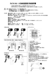
Maximum Value for OEMs
SM
CSDJ Plus Servo Drive
Installation Instructions
Contents
English....................................3
Chinese.................................21
Italian....................................39
English
Contents
Before Use .........................................................................5
Safety Instructions................................................................................................ 5
Operation.......................................................................................................... 6
Storage ............................................................................................................. 6
Carrying ............................................................................................................ 6
Installation and Wiring .................................................................................... 7
Maintenance & Checkup ................................................................................. 7
Checkpoints on Product Delivery ........................................................................ 8
Servo Drive....................................................................................................... 8
Servo Motor ..................................................................................................... 9
Installation and Test Run .................................................11
Installation and Wiring ....................................................................................... 11
Installation...................................................................................................... 11
Wiring ............................................................................................................. 13
Cautions for Wiring ...................................................................................... 14
Test Run............................................................................................................... 15
Power Input and Motor Configuration......................................................... 15
Gain Tuning.................................................................................................... 17
Operator Test Run ......................................................................................... 19
Troubleshooting ............................................................................................ 20
Important User Information
Solid state equipment has operational characteristics differing from those
of electromechanical equipment. Because of this difference, and also
because of the wide variety of uses for solid state equipment, all persons
responsible for applying this equipment must satisfy themselves that each
intended application of this equipment is acceptable.
In no event will OE Max Controls be responsible or liable for indirect or
consequential damages resulting from the use or application of this
equipment.
The examples and diagrams in this manual are included solely for
illustrative purposes. Because of the many variables and requirements
associated with any particular installation, OE Max Controls cannot
assume responsibility or liability for actual use based on the examples and
diagrams.
No patent liability is assumed by OE Max Controls with respect to use of
information, circuits, equipment, or software described in this manual.
Reproduction of the contents of this manual, in whole or in part, without
written permission of OE Max Controls is prohibited.
Throughout this manual we use notes to make you aware of safety
considerations.
WARNING
IMPORTANT
ATTENTION
Identifies information about practices or circumstances
which may lead to serious personal injury or death,
property damage, or economic loss.
Identifies information that is critical for successful
application and understanding of the product.
Identifies information about practices or circumstances
that can lead to minor personal injury, property damage,
economic loss, or product malfunction. However,
depending on situation, failure to follow the directions
accompanying this symbol may also lead to serious
consequences.
4
IMPORTANT
ATTENTION
1
Before Use
Safety Instructions
Please read the instructions and the User Manual thoroughly. It is
important that you become familiar with the operational issues prior
to installing and operating the machinery, to ensure optimal
error-free operation and maximize safety.
Before you start
• This manual is a summary of the required procedures that all
users must know for the proper handling, installation, and
execution of product test runs. It may not provide sufficient
information in all cases. Please refer to the User’s Manual for more
details.
• Product guarantees are not applicable in cases where modification
of the device by the user has been made in ways other than those
stated in this manual.
• In no case will OE Max Controls be responsible or liable for any
personal injury or property damage that is the result of improper
modification of the product.
5
Operation
ATTENTION
•
•
•
•
•
WARNING
•
•
•
Never touch the inside of the servo drive with your
hand.
Make sure your servo drive and motor are grounded.
Handle the drive only when the power is off and the
product is completely free of potential discharge.
(The lamplight will appear completely turned off.)
Avoid excessive stress on the motor’s power supply
and encoder cables.
Never touch the revolving motor component during
operation.
Avoid operation in environments that are subject to
conditions of humidity, corrosion, and flammability.
Operate without load during test runs.
The cooling panel of the drive is extremely hot while
in operation. Special caution is required at these
times.
Storage
ATTENTION
•
•
•
Avoid rain and humidity, and corrosive gases and
liquids.
Avoid direct sunlight and high temperatures and
avoid humidity levels that are outside the optimal
operational ranges.
Avoid overload of products in storage.
Carrying
ATTENTION
6
Don’t move or carry the device by its cable or motor
shaft.
Installation and Wiring
ATTENTION
•
•
ATTENTION
•
•
To prevent system damage caused by overheating,
the cooling system specifications must be included in
the design with consideration to ambient
temperature.
The cooling panel of the servo drive is extremely hot
during operation. Avoid the placement of wiring
cables in close proximity to the panel.
To prevent the negative impacts of noise and heat,
allow the separation of at least 10mm of space
between the drives if you are installing multiple
drives.
While wiring, we recommend highly that you make
allowance for the negative potential impact of noise.
Maintenance & Checkup
ATTENTION
•
•
•
Do not disassemble the device. The product warranty
is not applicable in cases of modification to the
product by the user in ways that are not
recommended by the stated procedures in this
manual. OE Max Controls is not responsible for
personal injury or property damage that is the result
of unsanctioned modifications to the product
Regular maintenance is critical for components with
limited service lives, and may require periodic
replacement due to normal mechanical friction and
degradation.
In case you cannot perform periodic troubleshooting,
contact our Technical Support Team or Customer
Service Center.
7
Checkpoints on Product Delivery
Please check the following on product delivery:
• Please check to see if the delivered product is identical with what
you ordered by referring to the legend.
• Check the screw contacts, lead shorts, insulators, and any other
signs of possible or apparent damage.
• For motors without brakes, turn the shafts with your hands and
verify that it revolves smoothly.
Servo Drive
Refer to the following legend, and verify that the model name written
on the nameplate on the side of the device is identical to that on your
order.
C S D J
Symbol
8
0
1 B X 2
Rated
Output
01
100[KW]
02
200[KW]
04
400[KW]
06
600[KW]
10
1[KW]
Symbol
Input Voltage
B
AC220[V]
O M
Servo Motor
Refer to the following legend, and verify that the model name that is
written on the nameplate on the servo motor device is identical to
that on your order.
The nameplate is attached on the motor. Check the model name on it.
Motor Model
C S M T
Motor Specification Symbol
0 1 B B 1 A N T 3
O M
Rated Output
Input Voltage
Encorder Type
Design No.
Motor Shaft Key
Option
Manufacturer
Motor Shaft Type
Motor Model
CSMT
CSMR
Rated Output
A3
30W
A5
50W
01
100W
02
200W
04
400W
06
600W
08
800W
10
1KW
01
100W
02
200W
04
400W
Input Voltage
B
AC220V
9
Encoder Type
CSMT, CSMR Motor
B
2048P/R
9 Wire Incremental Type
Motor Shaft Key
10
Option
Motor Shaft Type
A
Key
N
No Option
1
Round
(Coupling Contact)
B
No Key
B
Brake
3
Key Contact
2
Installation and Test Run
Installation and Wiring
Installation
Servo Drive
The Servo drive is designed to be mounted from the bottom. The following mounting direction is optimized to promote
the air cooling effects of natural convection. Make sure to mount the Servo Drive in this position to maximize the drive’s
integrity and operational life.
Outside Wall
Front View
Natural Convection
When installing multiple Servo drives, follow these guidelines:
Install the cooling fans to prevent the drives from overheating. The drives performance will become severely
compromised if they frequently operate in conditions that are outside the acceptable temperature range.
Cooling Fan
Cooling Fan
Over 50[mm]
Outside Wall
Over 50[mm]
Over 30[mm]
Over 10[mm]
11
Servo Motor
ATTENTION
•
•
•
•
Avoid excessive pressure to the motor shaft when it
has an attached load on the shaft. The encoder can
easily be damaged.
Position the load shaft to align it with the motor shaft.
Make sure the vertical and horizontal loads on the
motor shaft do not exceed the acceptable load range.
Refer to the User’s Manual for information on the
loads that the motor shaft can safely withstand.
Avoid excessive stress on the motor power supply
and the encoder cables.
Installation Environment
Item
Environment
Storage
Temperature
-20 ~ 80[° C]
Operating
Temperature
0 ~ 55[° C]
Operating
Humidity
Motor: 20 ~ 80[%] (non-condensing)
Servo Drive: below 90[%] (non-condensing)
Vibration
0.5[g] (4.9[m/s2])
Please work to keep the temperature within the
acceptable operating temperature range. If you
experience chronically excessively high ambient
temperatures, please install additional coolers.
Ambient
Recommended: For greater reliability and longer life,
operate the device at temperatures between 0 and
45[° C].
Your indoor operational environment must have
adequate ventilation, visibility, and easy access to
perform routine maintenance. Avoid the presence of
volatile gases.
12
Wiring
Use a push button. It is
used to turn the unit on.
Push it for about 1
second.
Connect when it is
necessary to immediately
turn the power off after
an alarm has started.
Make sure to
connect the
power supply
Earth to FG
Servo
Motor
Grounding Plate
ATTENTION
Frame or Chassis
One-point grounding
<3-type grounding or more>
Grounding
•
•
•
•
Only use power cables with capacities of over 600W.
Maintain the operating temperature between 40° C
and 60° C. Use a heatproof cable for operation outside
of this temperature range.
I/O wiring is not required for a test run(jog run). Refer
to the User’s Manual for information on I/O wiring for
best practices system construction.
The diagram above is recommended for complete
systems only. The power breaker is sufficient, and is
the only requirement for a test run.
13
Cautions for Wiring
Power Supply
ATTENTION
•
Make sure to connect the Power Supply Earth Servo
Drive FG and Motor FG. Otherwise, the Encoder
Feedback Signal or Drive Operation Command may
be negatively affected by noise.
User Input/Output
ATTENTION
•
•
Please check the pull-up resistance setting. Set the
pull-up resistance and confirm that it is set to the
recommended input current level, which is 10mA.
In the case of the line-drive output setting, the
recommended output voltage range is 2.8 ~ 3.7V, as it
is for the GND voltage.
Make sure to examine the pull-up
resistance setting.
Open Collector
Output
Master
Controller
ATTENTION
14
Servo Drive
When the user sets the output terminal wiring, please set
the resistance to conform to the recommended input
current, which is 10mA.
Test Run
Power Input and Motor Configuration
When the power is turned off and the major wiring tasks
(The connection of power supply, motor power, and motor encoder)
of the Servo Drive have been completed, the operator screen will
display as follows:
P: Position Control Mode
S: Speed Control Mode
t: Torque Control Mode
b-b: Preparing for operation
run: Operating
E.xx: An error occurred
Factory Default
Position
If the motor type of the connected motor is different from the factory
default, an encoder error may occur. Refer to the following:
Refer to Section 1.2.2, Motor Nameplate Legend, and check the
encoder type, motor type, and motor capacity, and set the values at
SEt-51, 52, and 53 respectively. The Critically Important values of
SEt-51, 52, 53 are shown in the table below. To save the new
values, reboot the drive by turning the drive off, and then on again.
SEt-51: CSMT, CSMR Motor Encoder
Symbol
Value
Encoder Type
PULSE
B
1
9 wire INC
2048
SEt-52: Motor Model
Motor
220VAC
CSMT
1042
CSMR
1062
SEt-53: Motor Capacity
Capacity [W]
30
50
100
……
1000
Value
3
5
10
……
100
15
Configuration Flow Chart
Set the integer using direction keys.
Make sure to save the values set
using MODE/SET keys.
Power off, and on again
Set the integers for SEt-52, 53 as shown above. You must turn the
Servo Drive off, and on again, to save the new values.
16
Gain Tuning
Auto Tuning
This is a general description about the gain tuning process. Auto
Tuning is a process for determining the inertia moment of the
applied load that is attached to the Servo Motor.
ENTER
ENTER
MODE
SET
ATTENTION
The motor rotates once in one direction and then
reverses direction during the tuning process. In case the
load is attached, make sure not to exceed the servo
motor’s allowable range.
Gain Tuning Flow
When making adjustment to the system again, SEt 42, after auto
tuning, the following gain level will adjust automatically based on the
changing inertia moment of the applied load.
SEt-02 Velocity Regulator proportional Gain
SEt-03 Velocity Regulator Integral Gain
SEt-04 Position Loop Proportional Gain
SEt-06 Torque Command 1st Filter Cutoff Frequency
SEt-40 Velocity Command 1st Filter Cutoff Frequency
17
Gain Tuning Flow Chart
•
Remarks
•
18
When the load moment ratio is below 1 after auto
tuning at USr-02, the gain cannot be adjusted to the
SEt-42 value. In such a case, manually change the load
moment ratio to 1 with the setting "SEt-66=10".
You can check the load moment ratio on Con-13.
Operator Test Run
Test Run Flow Chart
Forward
Revolution
Reverse
Revolution
19
•
•
•
Remarks
•
•
JOG operating speed is adjusted at SEt-25.
The default JOG operating speed is set to 500RPM.
Acceleration/deceleration time is adjusted at SEt-19
and 20 respectively.
Forward revolution is the counter-clock work
revolution as viewed from the front of the motor shaft.
In case of noise and vibration on the motor, perform
the gain tuning procedure once again.
Troubleshooting
Summary of troubleshooting guide on the test run.
Problem
20
Troubleshooting
E.80, E.81, E.82 Errors
These errors are related to an
incorrect integer setting. Initialize the
USr-09 integer and check the motor
type, motor capacity and the encoder
type settings again.
E.30, E.36 Errors
• Check the encoder type, and motor
type settings.
• Check the connection or wiring of
the encoder cable’s connector pin
connection for a potential short in
the wiring.
Excessive noise and vibration
• Check to see if the noise is coming
from the motor.
• Perform the Gain Tuning procedure
again.
简体中文
目录
使用之前 ........................................................................... 23
安全说明 .............................................................................................................. 23
操作 ................................................................................................................ 24
储存 ................................................................................................................ 24
运输 ................................................................................................................ 24
安装和接线 ..................................................................................................... 25
维护和检查 ..................................................................................................... 25
交付产品时的检查点 ............................................................................................ 26
伺服控制器 ..................................................................................................... 26
伺服器电机 ..................................................................................................... 27
安装和试机 ........................................................................ 29
安装和接线 ........................................................................................................... 29
安装 ................................................................................................................ 29
接线 ................................................................................................................ 31
接线注意事项 .................................................................................................. 32
试机 ..................................................................................................................... 33
电源输入和电机配置 ....................................................................................... 33
增益调节 ......................................................................................................... 35
操作员试机 ..................................................................................................... 37
故障排除 ......................................................................................................... 38
重要用户信息
固态电子设备的运行特性不同于机电设备。由于存在这种差异,而且,由
于固态电子设备具有各种不同的用途,因此,所有负责应用该设备的人必
须自己确保,此设备的每种预期用途都是可以接受的。
在任何情况下, OE Max Controls 对因使用或应用此设备导致的间接损害
或继发性损害均不承担任何责任。
本手册中包含的示例和图示只用于说明目的。由于任何特定安装都具有许
多相关的可变因素和要求,因此, OE Max Controls 不对基于示例和图示
的实际使用承担任何责任。
至于使用本手册中描述的信息、电路、设备或软件, OE Max Controls 不
承担任何专利责任。
如果没有 OE Max Controls 的书面批准,禁止全部或部分复制本手册的
内容。
在整个手册中,我们将使用各种标记来提醒您注意安全方面的事项。
警告
重要说明
注意
表示可能导致严重人身伤害或死亡、财产损失或经济损失的
做法或情况的信息。
表示对成功应用和了解本产品至关重要的信息。
表示可能导致轻微人身伤害、财产损失、经济损失或产品失
灵的做法或情况的信息。不过,根据实际情况,不遵守附有
此符号的指示可能也会导致严重后果。
22
÷ÿ“™ÀµÐ˜
Þ¢“‚
1
使用之前
安全说明
请通读以下说明和用户手册。在安装和运行设备之前,您应熟悉与设备运
转相关的问题,从而确保设备以最佳状态正常运转和最大限度地确保安
全,这一点至关重要。
开始之前
• 本手册概述了正确搬运、安装产品和进行产品试机所需遵循的步骤,所
有用户都必须了解这些步骤。但本手册提供的信息可能并不适用于所有
应用场合。有关详细信息,请参阅用户手册。
• 如果用户对设备进行了不符合本手册中规定的改动,产品保修将不再适
用。
• 对于因不当地改动本产品而导致的任何人身伤害或财产损失, OE Max
Controls 均不承担任何责任。
23
操作
注意
警告
•
•
•
•
绝对不要用手接触伺服控制器的内部。
确保伺服控制器和电机正确接地。
要搬运伺服控制器,必须关闭电源,并确保本产品绝对
不会放电。(灯光将完全熄灭。)
避免在电机的电源和编码器电缆上施加过大压力。
•
在设备运转过程中,切勿接触正在旋转的电机部件。
•
•
•
避免在受潮、腐蚀或易燃环境下运行本设备。
在对设备进行试机时,请空载运行。
在运行过程中,伺服控制器的散热板会特别热。此时必
须特别小心。
•
•
•
防雨、防潮、防腐蚀性气体或液体。
防阳光直射、防高温,防止湿度超出最佳工作湿度范围。
产品储存时切勿重压。
储存
注意
运输
注意
24
搬运本设备时,切勿抓住设备电缆或电机轴。
安装和接线
注意
•
•
注意
为了防止系统由于过热而损坏,设计时必须根据环境温
度制定冷却系统规格。
在运行过程中,伺服控制器的散热板会特别热。接线时,
切勿让电缆靠近散热板。
•
如果要安装多台伺服控制器,为了防止由于噪声和发热
而产生的不利影响,各台伺服控制器之间应至少留出
10 毫米的间隙。
•
接线时,极力建议应考虑噪声可能带来的不利影响。
•
请勿拆卸本设备。如果用户对设备进行了不符合本手册所
述步骤建议要求的改动,产品保修将不适用。如果用户未
经批准擅自对本产品进行改动,则对于由此引起的人身伤
害或财产损失, OE Max Controls 不承担任何责任。
对于使用寿命有限的元件而言,定期维护至关重要。而且
由于正常的机械摩擦和性能降低,可能需要定期更换这些
元件。
如果您无法定期进行故障排除,请与技术支持小组或客户
服务中心联系。
维护和检查
注意
•
•
25
交付产品时的检查点
交付产品时,请检查以下内容:
• 请参照图例检查交付的产品与订购的产品是否完全相同。
• 检查螺钉触点、短接线、绝缘体以及其他任何可能或明显出现破损的
迹象。
• 对于不带制动闸的电机,用手旋转电机轴,确认其平稳旋转。
伺服控制器
请参照下面的图例,验证该设备侧面铭牌上标注的型号是否与订单上的型
号完全相同。
C S D J
符号
26
0
1 B X 2
额定输出
01
100[KW]
02
200[KW]
04
400[KW]
06
600[KW]
10
1[KW]
符号
输入电压
B
AC220[V]
O M
伺服器电机
请参照下面的图例,验证伺服器电机设备的铭牌上标注的型号是否与订单
上的型号完全相同。
铭牌贴在电机上。请检查上面的型号。
电机型号
C S M T
电机规格符号
0 1 B B 1 A N T 3
O M
额定输出
输入电压
编码器类型
设计编号
电机轴键槽
选件
制造商
电机轴类型
电机型号
CSMT
CSMR
额定输出
A3
30W
A5
50W
01
100W
02
200W
04
400W
06
600W
08
800W
10
1KW
01
100W
02
200W
04
400W
输入电压
B
AC220V
27
编码器类型
CSMT, CSMR 电机
B
9 线步进式
2048P/R
电机轴键槽
28
选件
电机轴类型
A
键槽
N
无选件
1
圆形 (联轴节连接)
B
无键槽
B
制动闸
3
键槽连接
2
安装和试机
安装和接线
安装
伺服控制器
本款伺服控制器设计为从底部开始安装。以下安装方向是最佳的,可以加强空气自然对流的冷却效果。确保按此位置安装伺服
控制器,以最大程度地保证伺服控制器的完整性和延长其使用寿命。
外壁
自然对流
正视图
如果要安装多台伺服控制器,请遵循以下准则:
安装冷却风扇,以防止伺服控制器过热。如果伺服控制器经常工作在超出可接受温度范围的环境中,则其性能将受到严重营销。
冷却风扇
冷却风扇
大于 50[毫米]
外壁
大于 50[毫米]
大于 30[毫米]
大于 10[毫米]
29
伺服器电机
注意
•
•
•
•
当电机轴承受负载时,请不要对它施加过大压力。编码器
很容易损坏。
安装负载轴时,务必与电机轴对齐。
确保电机轴上的垂直负载和水平负载均不超过可接受的负
载范围。有关电机轴可安全承载的负载量的信息,请参阅
用户手册。
避免在电机的电源和编码器电缆上施加过大压力。
安装环境
项目
环境
存储温度
-20 ~ 80[°C]
工作温度
0 ~ 55[°C]
工作湿度
电机:20 ~ 80[%] (无冷凝)
伺服控制器:低于 90[%] (无冷凝)
振动
0.5[g] (4.9[m/s2])
请努力确保现场温度在可接受的工作温度范围内。如果
环境温度长期偏高,请另外安装散热装置。
环境
建议:为了提高可靠性和延长使用寿命,请在温度为
0 至 45[°C] 之间的环境中使用设备。
室内工作环境必须确保适当的通风和光线,并可以方便
地操作设备,进行常规维护。工作环境中不得存在挥发
性气体。
30
接线
使用按钮。该按钮的作用
是打开设备电源。请连续
按住大约 1 秒时间。
如果在启动警报后需要立
即关闭电源,请连接此继
电器。
确保将电源接
地连接到 FG
伺服器
电机
接地板
注意
机架或机箱
一点接地
<3 种以上接地方法>
接地
•
•
•
•
只可使用 600W 以上容量的电源线。
将工作温度保持在 40°C 到 60°C 之间。如果超出这一温度
范围,请使用耐热电缆。
试机 (慢速运行)时不要求对 I/O 进行接线。有关进行 I/O
接线以获得最佳系统结构的信息,请参阅用户手册。
上图只推荐用于完整系统。试机时,只需电源断路器就足
够了,这也是唯一的要求。
31
接线注意事项
电源
注意
•
确保将电源接地端连接到伺服控制器 FG 与电机 FG。否
则,编码器反馈信号或伺服控制器操作命令可能会受到噪
声干扰。
•
请检查上拉电阻设置。设置上拉电阻,并确认该电阻已
设置为建议的输入电流水平 10mA。
如果使用线路驱动输出设置,建议的输出电压范围为
2.8 ~ 3.7V (相对于 GND 电压)。
用户输入/输出
注意
•
确保检查上拉电阻设置。
开路集电极
输出
主站控制器
注意
32
伺服控制器
如果用户设置输出端子接线,请将电阻设置为与建议的输入
电流一致,即 10mA。
试机
电源输入和电机配置
在关闭电源并完成伺服控制器的主要接线任务 (电源、电机电源以及电机
编码器的连接)之后,操作员屏幕上将显示以下内容:
P:位置控制模式
S:速度控制模式
t:扭矩控制模式
b-b:准备运行
run:运行
E.xx:出现错误
工厂默认位置
如果所连接的电机的类型不同于工厂默认值,则会出现编码器错误。请参
阅以下内容:
请参阅第 1.2.2 小节的 “电机铭牌图例”,检查编码器类型、电机类型和电
机容量,并分别设置 SEt-51、 52 和 53 的值。下表中给出了 SEt-51、
52、 53 至关重要的值。要保存新值,请关闭并重新打开伺服控制器的电
源,以便重新启动它。
SEt-51:CSMT、 CSMR 电机编码器
符号
值
编码器类型
脉冲
B
1
9 线 INC
2048
SEt-52:电机型号
电机
220VAC
CSMT
1042
CSMR
1062
SEt-53:电机容量
容量 [W]
30
50
100
……
1000
值
3
5
10
……
100
33
配置流程图
使用方向键设置整数值。
务必使用 MODE/SET
键保存所设置的值。
关闭电源,
然后重新打开
按上述说明为 SEt-52、 53 设置整数值。要保存新值,必须先关闭伺服控制
器,然后重新打开。
34
增益调节
自动调节
以下概括介绍了增益调节过程。自动调节过程用于确定伺服器电机上所承
载的负载的惯性扭矩。
ENTER
ENTER
MODE
SET
注意
在调节过程中,电机首先朝一个方向旋转,然后反方向旋转。
在施加负载的情况下,确保负载不要超过伺服器电机的允许
负载范围。
增益调节流程
在自动调节之后,如果需要再次对系统 SEt 42 进行调整,系统将根据所加
负载不断变化的惯性扭矩,自动调整以下增益水平。
SEt-02 调速器比例增益
SEt-03 调速器积分增益
SEt-04 位置环比例增益
SEt-06 扭矩命令第一个滤波器截止频率
SEt-40 速度命令第一个滤波器截止频率
35
增益调节流程图
•
备注
•
36
如果在对 USr-02 进行自动调节后负载扭矩比低于 1,则
无法将增益调整为 SEt-42 值。在这种情况下,应使用设
置 “SEt-66=10”将负载扭矩比设置为 1。
您可以在 Con-13 上检查负载扭矩比。
操作员试机
试机流程图
正向旋转
反向旋转
37
备注
•
•
•
•
•
在 SEt-25 上调整 JOG 运行速度。
默认的 JOG 运行速度设置为 500RPM。
加速 / 减速时间可分别在 SEt-19 和 20 上调整。
从电机轴的前面看,正向旋转是逆时针方向旋转。
如果电机出现噪声和振动,请再次执行增益调节过程。
故障排除
试机过程中的故障排除指南概要。
问题
38
故障排除
E.80、 E.81、 E.82 错误
这些错误与整数设置不正确有关。初始
化 USr-09 整数,并再次检查电机类型、
电机容量和编码器类型设置。
E.30、 E.36 错误
• 检查编码器类型和电机类型设置。
• 检查编码器电缆的连接器针脚的连接
和接线,查看是否出现了短路。
噪声和振动过大
• 检查噪声是否源于电机。
• 再次执行增益调节过程。
Italiano
Sommario
Cenni preliminari .............................................................41
Istruzioni sulla sicurezza..................................................................................... 41
Modalità operativa......................................................................................... 42
Conservazione................................................................................................ 42
Trasporto ........................................................................................................ 42
Installazione e cablaggio............................................................................... 43
Manutenzione e controllo ............................................................................. 43
Verifica del prodotto alla consegna .................................................................. 44
Servoazionamento......................................................................................... 44
Servomotore .................................................................................................. 45
Installazione ed esecuzione del test ................................47
Installazione e cablaggio.................................................................................... 47
Installazione ................................................................................................... 47
Cablaggio ....................................................................................................... 49
Avvertenze per il cablaggio .......................................................................... 50
Esecuzione del test ............................................................................................. 51
Configurazione del motore e dell'alimentazione in ingresso .................... 51
Regolazione di guadagno ............................................................................. 53
Esecuzione del test dell'operatore ............................................................... 55
Risoluzione dei problemi .............................................................................. 56
Informazioni importanti per l’utente
I dispositivi a stato solido hanno caratteristiche operative diverse dai
dispositivi elettromeccanici. Considerata questa differenza e i diversi
impieghi dei dispositivi a stato solido, tutte le persone responsabili
dell’applicazione del presente dispositivo devono accertarsi che venga
utilizzato in modo appropriato.
In nessun caso OE Max Controls sarà responsabile di danni diretti o
indiretti dovuti all’utilizzo o all’applicazione del presente dispositivo.
Gli esempi e i diagrammi di questo manuale sono inclusi esclusivamente a
scopo illustrativo. A causa dei numerosi requisiti e variabili associati a ogni
installazione specifica, OE Max Controls non si assume alcuna
responsabilità per l'utilizzo effettivo basato su tali esempi e diagrammi.
OE Max Controls non si assume alcuna responsabilità relativa al brevetto
per l’utilizzo di informazioni, circuiti, apparecchiature o software descritti
nel presente manuale.
È vietata la riproduzione del contenuto del presente manuale, integrale o
parziale, senza previa autorizzazione scritta di OE Max Controls.
In tutto il manuale vengono utilizzate note per fornire all’utente indicazioni
sulla sicurezza.
AVVERTENZA
IMPORTANTE
ATTENZIONE
Identifica le informazioni su procedure o circostanze che
potrebbero causare lesioni gravi o la morte alle persone,
danni alle cose o perdite economiche di grande entità.
Identifica le informazioni importanti per consentire un
corretto utilizzo e la conoscenza del prodotto.
Identifica le informazioni su procedure o circostanze che
potrebbero causare lesioni alle persone, danni alle cose
o perdite economiche di lieve entità oppure un
malfunzionamento del prodotto. Tuttavia, a seconda
della situazione, la mancata osservanza delle indicazioni
contenute accanto al presente simbolo potrebbe
provocare serie conseguenze.
40
IMPORTANTE
ATTENZIONE
1
Cenni preliminari
Istruzioni sulla sicurezza
Leggere con attenzione le istruzioni e il manuale dell'utente. È
importante acquisire familiarità con le procedure operative prima di
eseguire l'installazione e di utilizzare il componente per garantire
un funzionamento corretto e la massima sicurezza.
Prima di iniziare
• Nel presente manuale è contenuto un riepilogo relativo alle
procedure necessarie per garantire la corretta gestione,
installazione ed esecuzione dei test del prodotto. Non vengono
tuttavia fornite informazioni dettagliate per tutti i casi esaminati.
Per ulteriori informazioni, fare riferimento al manuale dell'utente.
• La garanzia sul prodotto decade qualora le modifiche apportate al
dispositivo da parte dell'utente non siano conformi alle procedure
illustrate nel presente manuale.
• In nessun caso Rockwell Samsung sarà responsabile di danni al
prodotto o alle persone causati da un modifica inappropriata del
prodotto.
41
Modalità operativa
ATTENZIONE
•
•
•
•
•
AVVERTENZA
•
•
•
Non toccare mai l'interno il servoazionamento con le
mani.
Verificare la messa a terra del servoazionamento e del
motore.
Afferrare il servoazionamento solo quando
l'alimentazione è disattivata e il prodotto non può
causare alcuna scarica elettrica
(la spia luminosa è spenta).
Evitare di sovraccaricare l'alimentazione del motore e
i cavi del codificatore.
Non toccare mai il componente del motore rotante
quando è in funzione.
Evitare di operare in ambienti soggetti a condizioni di
umidità, corrosione e infiammabilità.
Utilizzare il prodotto senza carico durante l'esecuzione
del test.
Poiché il pannello di raffreddamento del
servoazionamento si surriscalda durante l'attività, si
consiglia di prestare particolare cautela.
Conservazione
ATTENZIONE
•
•
•
Evitare l'esposizione a pioggia, umidità, liquidi e gas
corrosivi.
Evitare l'esposizione diretta alla luce solare, a
temperature elevate, a livelli di umidità che non sono
compresi tra gli intervalli di attività ottimali.
Evitare il sovraccarico dei prodotti in conservazione.
Trasporto
ATTENZIONE
42
Non utilizzare il cavo o l'albero motore per spostare o
trasportare il dispositivo.
Installazione e cablaggio
ATTENZIONE
•
•
ATTENZIONE
•
•
Per evitare danni al sistema dovuti a
surriscaldamento, è necessario verificare che le
specifiche del sistema di raffreddamento siano adatte
alla temperatura ambiente.
Poiché il pannello di raffreddamento del
servoazionamento si surriscalda durante il
funzionamento, evitare di posizionare i cavi elettrici
vicino al pannello.
Per evitare disturbi e calore eccessivi, lasciare uno
spazio di almeno 10 mm tra ogni servoazionamento,
nel caso si installino più unità.
Durante il cablaggio, si consiglia di tenere presente un
potenziale impatto negativo delle interferenze.
Manutenzione e controllo
ATTENZIONE
•
•
•
Non smontare il dispositivo. La garanzia del prodotto
decade qualora le modifiche apportate al prodotto da
parte dell'utente non siano conformi alle procedure
illustrate nel presente manuale. Rockwell Samsung
non sarà responsabile per danni alle persone o alla
proprietà dovuti a modifiche non previste per il
prodotto.
È importante effettuare una regolare manutenzione
dei componenti con un ciclo di vita limitato. Inoltre
può rendersi necessaria una sostituzione periodica dei
componenti dovuta a usura e ad attrito meccanico.
Nel caso non sia possibile eseguire una periodica
risoluzione dei problemi, contattare il personale
addetto all'assistenza tecnica o il centro di assistenza.
43
Verifica del prodotto alla consegna
Al momento della consegna del prodotto, eseguire le seguenti
operazioni:
• Controllare se il prodotto fornito corrisponde a quanto ordinato
facendo riferimento alla legenda.
• Verificare i contatti delle viti, gli isolatori ed eventuali danni o
imperfezioni.
• Per i motori privi di freni, ruotare l'albero motore manualmente e
verificare che si ruoti con facilità.
Servoazionamento
Fare riferimento alla legenda che segue e verificare che il nome del
modello indicato sull'etichetta a lato del dispositivo corrisponda a
quello indicato nell'ordine.
C S D J
Simbolo
44
0
1 B X 2
Uscita
nominale
01
100[KW]
02
200[KW]
04
400[KW]
06
600[KW]
10
1[KW]
Simbolo
Tensione in
ingresso
B
c.a 220[V]
O M
Servomotore
Fare riferimento alla legenda che segue e verificare che il nome del
modello indicato sull'etichetta del servomotore corrisponda a quello
indicato nell'ordine.
L'etichetta del nome si trova sul motore. Verificare il nome del modello.
Modello motore
C S M T
Simbolo specifiche del motore
0 1 B B 1 A N T 3
O M
Uscita nominale
Tensione in ingresso
Tipo di codificatore
N. progetto
Chiave albero motore
Opzione
Produttore
Tipo di albero motore
Modello
motore
CSMT
CSMR
Uscita nominale
A3
30 W
A5
50 W
01
100 W
02
200 W
04
400 W
06
600 W
08
800 W
10
1 KW
01
100 W
02
200 W
04
400 W
Tensione in ingresso
B
c.a. 220V
45
Tipo di codificatore
Motore CSMT, CSMR
B
2048P/R
Tipo incrementale a 9 cavi
Chiave albero
motore
46
Opzione
A
Chiave
N
Nessuna
opzione
B
Nessuna
chiave
B
Freno
Tipo di albero motore
1
Tondo (contatto di
accoppiamento)
3
Contatto chiave
2
Installazione ed esecuzione del
test
Installazione e cablaggio
Installazione
Servoazionamento
Il servoazionamento è stato progettato per essere assemblato a partire dal basso. Le indicazioni per il montaggio
riportate di seguito sono state ottimizzate per favorire il raffreddamento ad aria per convezione naturale. Verificare
l'assemblaggio del servoazionamento in tale posizione per ottimizzare l'integrità e il ciclo di vita dell'unità.
Parete esterna
Vista frontale
Convezione naturale
Durante l'installazione di più servoazionamenti, attenersi alle seguenti linee guida:
installare le ventole di raffreddamento per evitare il surriscaldamento delle unità. Le prestazioni dell'unità verranno
seriamente compromesse in caso di utilizzo in ambienti con temperature non conformi all'intervallo consentito.
Ventola di
raffreddamento
Ventola di
raffreddamento
Oltre 50[mm]
Parete esterna
Oltre 50[mm]
Oltre 30[mm]
Oltre 10[mm]
47
Servomotore
ATTENZIONE
•
•
•
•
Evitare un'eccessiva pressione sull'albero motore
quando è dotato di carico. Il codificatore può
danneggiarsi facilmente.
Posizionare l'albero del carico in modo da allinearlo
all'albero motore.
Verificare che i carichi orizzontali e verticali dell'albero
motore non superino il carico consentito. Per
informazioni sui carichi consentiti per l'albero motore,
fare riferimento al manuale dell'utente.
Evitare di sovraccaricare l'alimentazione del motore e
i cavi del codificatore.
Ambiente di installazione
Caratteristica
Ambiente
Temperatura di
conservazione
-20 ~ 80[° C]
Temperatura in
modalità
operativa
0 ~ 55[°C]
Umidità in
modalità
operativa
Motore: 20 ~ 80[%] (senza condensa)
Servoazionamento: inferiore al 90[%] (senza
condensa)
Vibrazione
0,5[g] (4,9[m/s2])
È necessario mantenere la temperatura entro i valori
inclusi nell'intervallo della temperatura in modalità
operativa. Se si registra una temperatura ambiente
eccessivamente elevata, installare dispositivi di
raffreddamento aggiuntivi.
Ambiente
Consigliato: per una maggiore affidabilità e una
superiore durata, utilizzare il dispositivo in ambienti
con temperature comprese tra 0 e 45[° C].
L'ambiente operativo interno deve essere dotato di
ventilazione, visibilità e accesso facilitato adeguati
per eseguire interventi di manutenzione regolari.
Evitare la presenza di gas volatili.
48
Cablaggio
Utilizzare un pulsante
per attivare l'unità.
Tenerlo premuto per
circa 1 secondo.
Verificare di collegare
l'alimentazione alla
messa a terra della
struttura
Se necessario,
connettersi per disattivare
immediatamente
l'alimentazione dopo il
verificarsi di un allarme.
Servo
motore
Piastra di massa
ATTENZIONE
Struttura o telaio
Messa a terra a un punto
<Messa a terra di tipo 3 o superiore>
Messa a
terra
•
•
•
•
Utilizzare esclusivamente cavi elettrici con capacità
superiore a 600 W.
Mantenere la temperatura di funzionamento tra 40° C
e 60° C. Utilizzare un cavo resistente al calore in caso
di utilizzo con temperature non comprese in tale
intervallo.
Non è necessario il cablaggio I/O durante l'esecuzione
del test (esecuzione jog). Per informazioni sul
cablaggio I/O per creare un sistema ottimale, fare
riferimento al manuale dell'utente.
Si consiglia di utilizzare il diagramma sopra illustrato
solo per sistemi completi. Per eseguire il test infatti è
sufficiente disporre dell'interruttore di alimentazione.
49
Avvertenze per il cablaggio
Alimentazione
ATTENZIONE
•
Collegare la messa a terra del motore e della struttura
del servoazionamento all'alimentazione. In caso
contrario, il segnale di feedback del codificatore o il
dispositivo di controllo del servoazionamento può
subire interferenze a causa di disturbi.
Ingresso/uscita utente
ATTENZIONE
•
•
Verificare le impostazioni della resistenza di pull-up.
Impostare tale resistenza e confermare il livello di
corrente in ingresso consigliato pari a 10 mA.
Per l'impostazione in uscita del servoazionamento di
linea, l'intervallo di tensione in uscita consigliato è
compreso tra 2,8 ~ 3,7V, allo stesso modo della
tensione GND.
Verificare le impostazioni della resistenza
di pull-up.
Aprire l'uscita
del collettore
PLC
principale
ATTENZIONE
50
Servoazionamento
Durante l'impostazione del cablaggio del terminale in
uscita, regolare la resistenza in conformità alla corrente
in ingresso consigliata pari a 10 mA.
Esecuzione del test
Configurazione del motore e dell'alimentazione in
ingresso
Quando l'alimentazione è disattivata e le attività di cablaggio
principali(connessione dell'alimentazione, alimentazione del motore
e codificatore del motore) del servoazionamento sono state
completate, verrà visualizzata la seguente schermata dell'operatore:
P: modalità di controllo posizione
S: modalità di controllo velocità
t: modalità di controllo torsione
Posizione
predefinita
dal produttore
b-b: avvio
run: modalità operativa
E.xx: errore
Se il tipo del motore connesso è differente dal motore impostato
come predefinito, è possibile riscontrare un errore del codificatore. In
questo caso, fare riferimento a quanto segue:
Alla sezione 1.2.2, relativa alla legenda dell'etichetta del motore e
controllare il tipo di codificatore, di motore e la capacità del motore,
quindi impostare i valori rispettivamente per SEt-51, 52 e 53. Nella
tabella sottostante vengono illustrati i valori fondamentali per
SEt-51, 52 e 53. Per salvare i nuovi valori, è necessario riavviare
l'unità disattivandola e quindi attivandola nuovamente.
SEt-51: codificatore motore CSMT e CSMR
Simbolo
Valore
Tipo di
codificatore
IMPULSO
B
1
INC a 9 cavi
2048
SEt-52: modello motore
Motore
220 VAC
CSMT
1042
CSMR
1062
SEt-53: capacità motore
Capacità [W]
30
50
100
……
1000
Valore
3
5
10
……
100
51
Diagramma del flusso di configurazione
Impostare i numeri interi utilizzando
i tasti di direzione.
Salvare i valori impostati mediante i
tasti MODE/SET.
Spegnere il sistema,
quindi, riavviarlo.
Impostare i numeri interi per SEt-52, 53 come riportato
precedentemente. È necessario disattivare il servoazionamento,
quindi riavviarlo per salvare i nuovi valori impostati.
52
Regolazione di guadagno
Regolazione automatica
Viene fornita una descrizione generale del processo di regolazione
del guadagno. Per regolazione automatica s'intende il processo
che consente di determinare il momento di inerzia del carico
applicato al servomotore.
ENTER
ENTER
MODE
SET
ATTENZIONE
Durante il processo di regolazione il motore viene fatto
prima ruotare in una direzione, quindi in quella opposta.
Nel caso in cui si applica un carico, non superare
l'intervallo consentito per il servomotore.
Flusso di regolazione di guadagno
Quando si regola nuovamente il sistema in SEt 42, successivamente
alla regolazione automatica, viene impostato automaticamente il
seguente livello di guadagno in base alla modifica del momento di
inerzia del carico applicato.
SEt-02 Guadagno proporzionale del regolatore di velocità
SEt-03 Guadagno integrale del regolatore di velocità
SEt-04 Guadagno proporzionale del loop di posizionamento
SEt-06 Frequenza primo filtro del comando di torsione
SEt-40 Frequenza primo filtro del comando di velocità
53
Diagramma del flusso di regolazione guadagno
•
Note
•
54
Quando il rapporto del momento di carico è inferiore
a 1 in seguito alla regolazione automatica per il valore
USr-02, non è possibile regolare il guadagno per il
valore SEt-42. In simili casi, impostare manualmente il
rapporto del momento di carico su 1 mediante "SEt66=10".
È possibile controllare il rapporto del momento di
carico su Con-13.
Esecuzione del test dell'operatore
Diagramma del flusso di esecuzione del test
Rotazione
avanti
Rotazione
indietro
55
•
•
Note
•
•
•
La velocità operativa JOG viene regolata in SEt-25.
Per impostazione predefinita, la velocità operativa
JOG è pari a 500 gpm.
Il tempo di accelerazione/decelerazione viene regolato
rispettivamente in SEt-19 e 20.
La rotazione in avanti rappresenta la rotazione
operativa in senso antiorario come indicato nella
parte anteriore dell'albero motore.
In caso di rumori e vibrazioni del motore, eseguire
nuovamente la procedura di regolazione del
guadagno.
Risoluzione dei problemi
Viene fornito un riepilogo relativo agli argomenti contenuti nella
guida per la risoluzione dei problemi che è possibile riscontrare
durante l'esecuzione del test.
Problema
56
Risoluzione del problema
Errori E.80, E.81, E.82
Questi errori sono dovuti a un'errata
impostazione dei numeri interi.
Inizializzare il numero intero USr-09 e
controllare le impostazioni relative al
tipo, alla capacità del motore e al tipo
di codificatore.
Errori E.30, E.36
• Controllare le impostazioni del tipo
del codificatore e del motore.
• Controllare la connessione o il
cablaggio del collegamento del pin
del connettore relativo al cavo del
codificatore in caso di un potenziale
cortocircuito.
Rumori e vibrazioni eccessivi
• Controllare se il rumore proviene
dal motore.
• Eseguire nuovamente la procedura
di regolazione del guadagno.
CSDJ Plus Servo Drive
Installation Instructions
OE MAX Controls
www.oemax.com
Publication CSDJP-IN001A-MU-P
Copyright © 2004 OE MAX Controls