1
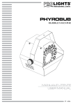
H150UFC FOG MACHINE MANUALE UTENTE USER MANUAL IT - EN Music & Lights S.r.l. si riserva ogni diritto di elaborazione in qualsiasi forma delle presenti istruzioni per l’uso. La riproduzione - anche parziale - per propri scopi commerciali è vietata. Al fine di migliorare la qualità dei prodotti, la Music&Lights S.r.l. si riserva la facoltà di modificare, in qualunque momento e senza preavviso, le specifiche menzionate nel presente manuale di istruzioni. Tutte le revisioni e gli aggiornamenti sono disponibili nella sezione 'Manuali' sul sito www.musiclights.it REV.001-05/14 H150UFC INDICE Sicurezza Avvertenze generali Attenzioni e precauzioni per l’installazione Informazioni generali 4 4 5 1 Introduzione 1. 1 Specifiche tecniche 1. 2 Elementi di comando e di collegamento 6 7 2 Funzioni e impostazioni 2. 1 Pannello di controllo 2. 2 Impostazione base 2. 3 Funzionamento 2. 4 Sistema di controllo wireless 2. 5 Set up dei trasmettitori 2. 6 Sostituzione della batteria del trasmettitore 2. 7 Struttura menu 2. 8 Modalità DMX 2. 9 Indirizzamento DMX 2. 10 Collegamenti della linea DMX 2. 11 Costruzione del terminatore DMX 2. 12 Canali DMX 2. 13 Modalità master/slave 2. 14 Modalità colore 2. 15 Modalità colori statici 2. 16 Modalità colori dinamici 2. 17 Tempo di intervallo 2. 18 Tempo di durata 2. 19 Impostazioni wireless 2. 20 Programmazione tasto A 2. 21 Programmazione tasto B 2. 22 Programmazione tasto C 2. 23 Programmazione tasto D 2. 24 Modalità di accensione LED 2. 25 Tempo di ritardo LED 2. 26 Esecuzione delle ultime impostazioni 8 8 9 9 10 10 11 12 12 14 14 15 16 16 16 16 16 16 17 17 17 17 17 17 18 18 3 Manutenzione 3. 1 Pulizia e manutenzione 3. 2 Riarmo del fusibile 3. 3 Risoluzione dei problemi 19 19 19 Certificato di garanzia Contenuto dell'imballo: 3 • • • • H150UFC Telecomando wireless Cavo di alimentazione Manuale utente H150UFC 4 ATTENZIONE! Prima di effettuare qualsiasi operazione con l’unità, leggere con attenzione questo manuale e conservarlo accuratamente per riferimenti futuri. Contiene informazioni importanti riguardo l’installazione, l’uso e la manutenzione dell’unità. SICUREZZA Avvertenze generali • I prodotti a cui questo manuale si riferisce sono conformi alle Direttive della Comunità Europea e pertanto recano la sigla . • Il dispositivo funziona con pericolosa tensione di rete 230V~. Non intervenire mai al suo interno al di fuori delle operazioni descritte nel presente manuale; esiste il pericolo di una scarica elettrica. • È obbligatorio effettuare il collegamento ad un impianto di alimentazione dotato di un’efficiente messa a terra (apparecchio di Classe I secondo norma EN 60598-1). Si raccomanda, inoltre, di proteggere le linee di alimentazione delle unità dai contatti indiretti e/o cortocircuiti verso massa tramite l’uso di interruttori differenziali opportunamente dimensionati. • Le operazioni di collegamento alla rete di distribuzione dell’energia elettrica devono essere effettuate da un installatore elettrico qualificato. Verificare che frequenza e tensione della rete corrispondono alla frequenza ed alla tensione per cui l’unità è predisposta, indicate sulla targhetta dei dati elettrici. • L’unità non per uso domestico, solo per uso professionale. • Evitare di utilizzare l’unità: - in luoghi a temperatura superiore ai 45°C; - in luoghi soggetti a vibrazioni, o a possibili urti; - in luoghi soggetti ad eccessiva umidità. • Evitare che nell’unità penetrino liquidi infiammabili, acqua o oggetti metallici. • Non smontare e non apportare modifiche all’unità. • Tutti gli interventi devono essere sempre e solo effettuati da personale tecnico qualificato. Rivolgersi al più vicino centro di assistenza tecnica autorizzato. • Se si desidera eliminare il dispositivo definitivamente, consegnarlo per lo smaltimento ad un’istituzione locale per il riciclaggio. Attenzioni e precauzioni per l’installazione • Questo prodotto è solo per uso interno. • Se il dispositivo dovesse trovarsi ad operare in condizioni differenti da quelle descritte nel presente manuale, potrebbero verificarsi dei danni; in tal caso la garanzia verrebbe a decadere. Inoltre, ogni altra operazione potrebbe provocare cortocircuiti, incendi, scosse elettriche, rotture etc. • Togliere tutto il materiale di imballo. Vicino alla bocca di erogazione non si devono trovare resti dell’imballaggio. • Disconnettere l’unità dalla rete elettrica quando non è in uso, quando si effettua il riempimento del serbatoio, o quando si cambia un fusibile. • Lasciare che la macchina del fumo si raffreddi prima di qualsiasi operazione di pulizia o di manutenzione. • Non accendere e spegnere il dispositivo a brevi intervalli, potrebbe ridurre la durata del dispositivo. • Se il dispositivo è stato esposto a forti sbalzi termici (es: per trasporto), non accenderlo immediatamente. L’umidità potrebbe danneggiare il dispositivo. Lasciare il dispositivo spento fino a quando ha raggiunto la temperatura ambiente. • Se il dispositivo cade o subisce gravi urti, scollegare immediatamente la spina di alimentazione. Chiamare un tecnico qualificato per verificare la sicurezza della macchina prima del suo utilizzo. • Nel caso di funzionamento anomalo, smettere di utilizzare l’unità e rivolgersi ad un centro di assistenza tecnica autorizzato. Assicurarsi di svuotare il serbatoio prima di spostare o effettuare la spedizione. H150UFC 5 • Durante il funzionamento, l’ugello di erogazione del fumo diventa molto caldo. Non toccarlo e mantenere materiali infiammabili ad una distanza di sicurezza dall’unità (almeno 50 cm). • Assicuratevi sempre che vi sia sufficiente liquido nel serbatoio. Il funzionamento di questa unità senza liquido può causare danni alla pompa. Evitare pure il surriscaldamento. • Utilizzare liquidi Prolights a base d’acqua. • Non riempire troppo l’unità: un riempimento eccessivo potrebbe provocare intasamento. Svuotare il serbatoio dell’unità quando non è in funzione o non utilizzata per lunghi periodi. • Non aggiungere mai liquidi infiammabili di qualsiasi tipo (petrolio, gas, profumi) al liquido della macchina. • Tenere sempre il tappo del serbatoio chiuso durante il funzionamento. • Non bere il liquido per il funzionamento della macchina. Se viene ingerito, chiamare immediatamente un medico. Inoltre, se il liquido nebbia entra in contatto con la pelle o gli occhi, sciacquare abbondantemente con acqua. • Questa macchina non è impermeabile. Se altri liquidi dovessero entrare nell’unità scollegarla dalla rete di alimentazione. Rivolgersi al centro di assistenza tecnica autorizzato per le condizioni di sicurezza all’utilizzo. • Posizionare l’unità in un posto ventilato. Non coprire le aperture dell’unità. Al fine di garantire un’adeguata ventilazione, lasciare uno spazio libero di 20 cm da altri oggetti. • Tenere la macchina in posizione orizzontale; non metterla mai in posizione inclinata. • Orientare l’unità in modo tale che il flusso di fumo non colpisca direttamente le persone, animali o cose. • Non puntare l’ugello di erogazione su fiamme libere. • Non rimuovere avvisi o etichette informative dall’unità. • Assicurarsi che il cavo di alimentazione non sia rovinato. Controllare prima di ogni utilizzo. INFORMAZIONI GENERALI Spedizioni e reclami Le merci sono vendute “franco nostra sede” e viaggiano sempre a rischio e pericolo del distributore/cliente. Eventuali avarie e danni dovranno essere contestati al vettore. Ogni reclamo per imballi manomessi dovrà essere inoltrato entro 8 giorni dal ricevimento della merce. Garanzie e resi Il prodotto è coperto da garanzia in base alle vigenti normative. Sul sito www.musiclights.it è possibile consultare il testo integrale delle “Condizioni Generali di Garanzia”. Si prega, dopo l’acquisto, di procedere alla registrazione del prodotto sul sito www.musiclights.it. In alternativa il prodotto può essere registrato compilando e inviando il modulo riportato alla fine del manuale. A tutti gli effetti la validità della garanzia è avallata unicamente dalla presentazione del certificato di garanzia. Music & Lights constata tramite verifica sui resi la difettosità dichiarata, correlata all’appropriato utilizzo, e l’effettiva validità della garanzia; provvede quindi alla riparazione dei prodotti, declinando tuttavia ogni obbligo di risarcimento per danni diretti o indiretti eventualmente derivanti dalla difettosità. H150UFC 6 - 1 - INTRODUZIONE 1.1 SPECIFICHE TECNICHE • Tensione di ingresso: AC 220-240V 50/60 Hz • Fusibile: 230V = 9A 250V • Caldaia: 1550W • Tempo di preriscaldamento: 5 min (circa) • Volume di copertura: altezza 5 m, larghezza 1 m • Tempo di funzionamento massimo: 8 sec full output • Capacità tanica liquido: 2,4 lt • Consumo liquido: 25ml/10sec full output • Fluido: Liquidi Prolights a base d’acqua serie SmokeFluid • Opzioni di controllo: DMX 512, manuale, timer, telecomando wireless • Canali DMX: 8 canali • Cavo di alimentazione: Neutrik Powercon • Connessioni DMX: XLR a 3 pin IN/OUT, XLR a 5 pin IN/OUT • Dimensioni (WxHxD): 418x295x210 mm • Peso: 10.4 kg MODELLO H150UFC Voltaggio AC 220-240V 50/60 Hz Caldaia 1550W Consumo liquido 25ml/10sec full output Dimensioni (WxHxD) 418x295x210 mm Peso 10,4 kg Capacità serbatoio liquido 2,4 litri H150UFC 7 1.2 ELEMENTI DI COMANDO E DI COLLEGAMENTO 2 3 1 4 3 11 10 B A 9 8 7 12 6 5 Pannello Posteriore 1. 2. 3. 4. 5. UGELLO PANNELLO LED MANIGLIE VANO PER SERBATOIO SAFETY RING per l’aggancio al cavo di sicurezza. 6. CONNETTORI: -- DMX IN (XLR a 3 poli): 1= ground, 2 = DMX -, 3 = DMX + -- DMX IN (XLR a 5 poli): 1= massa, 2 = DMX -, 3 = DMX +, 4 N/C, 5 N/C -- DMX OUT (XLR a 3 poli): 1= massa, 2 = DMX -, 3 = DMX + Fig.1 -- DMX OUT (XLR a 5 poli): 1= massa, 2 = DMX -, 3 = DMX +, 4 N/C, 5 N/C 7. POWER IN (connettore di potenza): per il collegamento ad una presa ri rete (220-240V~/50-60Hz) tramite il cavo rete in dotazione. 8. CIRCUIT BREAKER 9. PANNELLO DI CONTROLLO 10. RICEVITORE WIRELESS 11. VENTOLA PER IL RAFFREDDAMENTO 12. TRASMETTITORE WIRELESS H150UFC 8 - 2 - FUNZIONI E IMPOSTAZIONI 2.1 PANNELLO DI CONTROLLO L’H150UFC dispone di un display LCD e 4 pulsanti per accesso alle funzioni del pannello di controllo (fig2). MENU Per scorrere il menu principale UP/TIMER Per scorrere attraverso le diverse funzioni in ordine discendente o attivare la funzione Timer DOWN/VOLUME Per scorrere attraverso le diverse funzioni in ordine ascendente o attivare la funzione Volume STOP Per disattivare le funzioni Timer e Volume Fig.2 - Funzione dei tasti 2.2 IMPOSTAZIONE BASE 1. Togliere tutto il materiale di imballo. Vicino all’ugello di erogazione non si devono trovare resti dell’imballaggio. 2. Posizionare l’unità su un piano orizzontale, svitare la vite posta sul pannello posteriore, togliere il pannello laterale e infine svitare il tappo del serbatoio. 3. Versare il liquido Prolights, per fumo a base di acqua, nel serbatoio senza superare il livello massimo per evitare che trabocchi. Raccogliere subito con un panno asciutto il liquido eventualmente rovesciato per evitare che entri dentro alla macchina. L’unità non è protetta contro gli spruzzi d’acqua. Se del liquido finisce all’interno, non mettere in funzione la macchina, ma rivolgersi, per un controllo, al più vicino centro di assistenza tecnica autorizzato. 4. La macchina funziona solo con il relativo liquido Prolights della serie SMOKEFLUID. Eventuali altri tipi di liquido possono danneggiare l’unità. Durante il riempimento la macchina non deve essere collegata con la rete elettrica. Staccare prima la spina dalla presa. 5. Avvitare il tappo e controllare che il tubo d’aspirazione arrivi fino al fondo del serbatoio. EVITARE CHE L’UNITÀ RIMANGA SENZA IL LIQUIDO DEL FUMO: LA POMPA POTREBBE DANNEGGIARSI. NOTE • Le macchine per il fumo tendono a sviluppare condensa intorno all’ugello di emissione. Questo può comportare un accumulo di liquido sulla superficie sotto l’ugello. Considerare questo particolare dovendo decidere dove installare l’unità. H150UFC 9 • Queste macchine possono espellere piccole quantità di fumo occasionalmente durante il funzionamento e per circa un minuto dopo lo spegnimento. • Tutte le macchine, dopo un lungo periodo di erogazione fumo, necessitano di riportare la temperatura a quella di esercizio. Durante questo tempo nessuna erogazione di fumo può essere effettuata. 2.3 FUNZIONAMENTO Per accendere l’H150UFC, collegare l’estensione POWER IN al cavo di alimentazione e inserire la spina in una presa di rete (100-240V~/50-60Hz). L’unità può essere comandata manualmente, da un unità DMX di comando luce, tramite la funzione Timer oppure tramite il telecomando wireless in dotazione. Per emettere fumo con la macchina, fare riferimento alla seguente guida: 1. Aggiungere il liquido fumo nel serbatoio facendo attenzione che non trabocchi. 2. Collegare il cavo di alimentazione ad una presa elettrica. La macchina entrerà in funzione. Attendere alcuni minuti per il riscaldamento della macchina (5 minuti circa). Durante il tempo di riscaldamento non può essere effettuata nessuna erogazione di fumo. Il processo di riscaldamento risulterà completato quando sul display apparirà la scritta “Ready to Fog”. Quindi l’unità è pronta per l’uso. 3. Per iniziare ad emettere fumo in modalità manuale, premere il pulsante Volume collocato sul pannello di controllo. 4. Per terminare l’emissione di fumo, premere il pulsante STOP collocato sul pannello di controllo. 5. Per il funzionamento mediante telecomando wireless fare riferimento alle impostazioni indicate nel relativo paragrafo. Importante: • Durante il funzionamento monitorare costantemente il livello di liquido nel serbatoio. • Non bere il liquido per fumo. Se viene ingerito, chiamare immediatamente un medico. Inoltre, se il liquido per fumo entra in contatto con la pelle o gli occhi, sciacquare abbondantemente con acqua. • Dopo il riempimento del serbatoio, avvitare sempre il tappo per evitare contaminazioni. NOTE - Nel caso di rumori della pompa o piccole erogazioni di fumo, scollegare immediatamente l’unità dalla rete elettrica. Controllare il livello del liquido, il tubo collegato al serbatoio, il fusibile esterno e l’alimentazione elettrica. Se queste verifiche risultano soddisfatte collegare nuovamente l’unità alla rete elettrica e riprovare. Se nessuna emissione viene effettuata dopo aver premuto il tasto del pannello di controllo per 30 secondi, non continuare per non recare danni all’unità ma rivolgersi al più vicino centro di assistenza tecnica autorizzato. Per spegnere il l’H150UFC, staccare la spina dalla presa di rete. Per maggiore comodità è consigliabile collegare l’unità con una presa comandata da un interruttore. 2.4 SISTEMA DI CONTROLLO WIRELESS Il sistema di controllo wireless è composto da un trasmettitore (fig.3), dotato di qua pulsanti attivazione e disattivazione erogazione fumo, e di un ricevitore (fig.4) pre-collegato al pannello posteriore dell’unità. Trasmettitore Mediante il trasmettitore wireless (fig.3) è possibile attivare, via radio, ad una distanza massima di 50 metri, la produzione di fumo. Ricevitore Il ricevitore wireless (fig.4) è testato e pre-fissato al pannello di controllo dell’H150UFC. Si prega di non cercare di rimuoverlo. Il ricevitore risponde fino a 10 diversi trasmettitori che sono associati con la macchina. 10 H150UFC B A Il trasmettitore in dotazione è stato associato con la macchina prima della spedizione. Quindi può essere attivato senza alcuna ulteriore impostazione. Fig.3 - Trasmettitore Fig.4 - Ricevitore 2.5 SET UP DEI TRASMETTITORI Per il funzionamento della macchina con un trasmettitore diverso da quello in dotazione, o nel caso di funzionamento con trasmettitori differenti (fino a 10), è necessario che ciascun trasmettitore sia settato. Far riferimento alla seguente guida per associare o cancellare un trasmettitore al ricevitore. 1. Spegnere l’H150UFC. 2. Tenere premuto il tasto DOWN collocato sul pannello di controllo dell’unità. 3. Accendere l’H150UFC e rilasciare il tasto DOWN quando il display LCD lampeggia. 4. Tenere premuto il tasto A collocato sul trasmettitore. 5. Per associare il trasmettitore al ricevitore, premere il tasto UP collocato sul pannello di controllo dell’unità e infine il tasto STOP mentre per rimuovere il trasmettitore dal ricevitore, premere il tasto DOWN collocato sul pannello di controllo dell’unità e infine il tasto STOP. 2.6 SOSTITUZIONE DELLA BATTERIA DEL TRASMETTITORE Assicurarsi che i ricevitori wireless non superino la distanza massima dal trasmettitore. Se la capacità di trasmissione diminuisce, è probabile che la batteria del trasmettitore si sia esaurita e che quindi debba essere sostituita; pertanto rimuovere il coperchio posteriore estraendo le tre viti e inserire una nuova batteria dello stesso tipo e con le stesse caratteristiche di quella vecchia (27A 12V). H150UFC 2.7 STRUTTURA MENU MENU 1 ð DMX 512 Address: 1 ... Address: 504 2 ð Stand Alone Set Master Set Slave 3 ð Color Mode ON OFF 4 ð Color Mode Macro: 01 ... Macro: 10 5 ð Color Mode Chase: 01 ... Chase: 15 6 ð Timer Interval 15 Sec ... Interval 360 Sec 7 ð Timer Duration 1 Sec ... Duration 5 Sec 8 Wireless Setting ð ON OFF 9 Wireless Setting ð Button A:M01 ... Button A:M10 Button A:C01 ... Button A:C15 Button A:OFF 10 Wireless Setting ð Button B:M01 ... Button B:M10 Button B:C01 ... Button B:C15 Button B:OFF 11 H150UFC 12 11 Wireless Setting ð Button C:M01 ... Button C:M10 Button C:C01 ... Button C:C15 Button C:OFF 12 Wireless Setting ð Button D:M01 ... Button D:M10 Button D:C01 ... Button D:C15 Button D:OFF 13 LED Setting ð Fog only Always On 14 LED Fade out ð Delay: 0 Sec ... Delay: 5 Sec 15 Run Last Setting ð ON OFF 2.8 MODALITÀ DMX Per entrare nella modalità DMX procedere nel seguente modo: • Premere il tasto MENU fino a quando sul display non appare la voce DMX 512. • Premere i tasti UP/DOWN per selezionare l’indirizzo DMX al valore desiderato e compreso tra 1 e 504 (tenere premuto per lo scorrimento veloce). Premere il tasto STOP per uscire dal menù d’impostazione. 2.9 INDIRIZZAMENTO DMX L’ H150UFC dispone di 1 configurazione DMX a 8 canali. Le tabella a pagina 15 indica la modalità di funzionamento e i relativi valori DMX. Come interfaccia DMX, l’unità possiede dei contatti XLR a 3 poli e 5 poli. Per poter comandare l’H150UFC con un’unità di comando luce, occorre impostare l’indirizzo di start DMX per il primo canale DMX. Se, per esempio, sull’unità di comando è previsto l’indirizzo 33 per comandare la funzione del primo canale DMX, si deve impostare sull’H150UFC l’indirizzo di start 33. Le altre funzioni del pannello saranno assegnate automaticamente agli indirizzi successivi. Segue un esempio con indirizzo 33 di start: H150UFC 13 Numero canali DMX Indirizzo di start (esempio) Indirizzo DMX occupati Prossimo indirizzo di start possibile per unità n°1 Prossimo indirizzo di start possibile per unità n°2 Prossimo indirizzo di start possibile per unità n°3 8 33 33-40 41 49 57 DMX Address: 33 DMX Address: 41 DMX Address: 49 DMX Address: 57 . . . . . . . . . . . . DMX512 Controller Fig.5 - Esempio di configurazione a 8 canali DMX H150UFC 14 2.10 COLLEGAMENTI DELLA LINEA DMX La connessione DMX è realizzata con connettori standard XLR. Utilizzare cavi schermati, 2 poli ritorti, con impedenza 120Ω e bassa capacità. Per il collegamento fare riferimento allo schema di connessione riportato di seguito: DMX - INPUT Spina XLR DMX - OUTPUT Presa XLR Pin1 : Massa - Schermo Pin2 : - Negativo Pin3 : + Positivo Pin4 : N/C Pin5 : N/C Fig.6 ATTENZIONE La parte schermata del cavo (calza) non deve mai essere collegata alla terra dell’impianto; ciò comporterebbe malfunzionamenti delle unità e dei controller. Per passaggi lunghi può essere necessario l’inserimento di un amplificatore DMX. In tal caso, è sconsigliato utilizzare nei collegamenti cavo bilanciato microfonico poiché non è in grado di trasmettere in modo affidabile i dati di controllo DMX. • Collegare l’uscita DMX del controller con l’ingresso DMX della prima unità; • Collegare, quindi, l’uscita DMX con l’ingresso DMX della successiva unità; l’uscita di quest’ultima con l’ingresso di quella successiva e via dicendo finchè tutte le unità sono collegate formando una catena. • Per installazioni in cui il cavo di segnale deve percorrere lunghe distanze è consigliato inserire sull’ultima unità una terminazione DMX. 2.11 COSTRUZIONE DEL TERMINATORE DMX La terminazione evita la probabilità che il segnale DMX 512, una volta raggiunta la fine della linea stessa venga riflesso indietro lungo il cavo, provocando, in certe condizioni e lunghezze, la sua sovrapposizione al segnale originale e la sua cancellazione. La terminazione deve essere effettuata, sull’ultima unità della catena, con connettori XLR a 3/5 pin, saldando una resistenza di 120Ω (minimo 1/4W) tra i terminali 2 e 3, così come indicato in figura. Esempio: connettore XLR a 3 pin Fig.7 H150UFC 15 2.12 CANALI DMX MODE 8 Ch FUNCTION DMX Value 1 FOG Fog off Fog on 000 - 004 005 - 255 2 RED 0~100% 000 - 255 3 GREEN 0~100% 000 - 255 4 BLUE 0~100% 000 - 255 5 CHASE Chase 1 Chase 2 Chase 3 Chase 4 Chase 5 Chase 6 Chase 7 Chase 8 Chase 9 Chase 10 Chase 11 Chase 12 Chase 13 Chase 14 Chase 15 000 - 015 016 - 031 032 - 047 048 - 063 064 - 079 080 - 095 096 - 111 112 - 127 128 - 143 144 - 159 160 - 175 176 - 191 192 - 207 208 - 223 224 - 255 6 CHASE SPEED 0 - 255 step per min 000 - 255 7 MASTER DIMMER 0~100% 000 - 255 8 STROBE 1 - 20 Hz 000 - 255 16 H150UFC 2.13 MODALITÀ MASTER/SLAVE Questa modalità consente di collegare in linea più unità senza un controller. La prima unità sarà impostata come Master e le altre funzioneranno come Slave con lo stesso effetto. • Premere il tasto MENU fino a quando sul display non appare la voce Stand Alone. • Premere i tasti UP/DOWN per selezionare la modalità Set Master per impostare l’unità come Master oppure la modalità Set Slave per impostare l’unità come Slave. Premere il tasto STOP per uscire dal menù d’impostazione. 2.14 MODALITÀ COLORE Per impostare la modalità colore nella modalità di funzionamento manuale, fare riferimento alla seguente procedura. • Premere il tasto MENU fino a quando sul display non appare la voce Color Mode. • Premere i tasti UP/DOWN per selezionare la modalità ON oppure OFF. Premere il tasto STOP per uscire dal menù d’impostazione. 2.15 MODALITÀ COLORI STATICI Per impostare la modalità show con colori statici nella modalità di funzionamento manuale, fare riferimento alla seguente procedura. • Premere il tasto MENU fino a quando sul display non appare la voce Color Mode (Macro). • Premere i tasti UP/DOWN per selezionare la modalità desiderata Macro:01 - Macro:10 (tenere premuto per lo scorrimento veloce). Premere il tasto STOP per uscire dal menù d’impostazione. 2.16 MODALITÀ COLORI DINAMICI Per impostare la modalità show con colori dinamici nella modalità di funzionamento manuale, fare riferimento alla seguente procedura. • Premere il tasto MENU fino a quando sul display non appare la voce Color Mode (Chase). • Premere i tasti UP/DOWN per selezionare la modalità desiderata Chase:01 - Chase:15 (tenere premuto per lo scorrimento veloce). Premere il tasto STOP per uscire dal menù d’impostazione. 2.17 TEMPO DI INTERVALLO Per impostare l’intervallo di tempo che intercorre tra un’emissione di fumo e l’altra, fare riferimento alla seguente procedura. • Premere il tasto MENU fino a quando sul display non appare la voce Timer (Interval). • Premere i tasti UP/DOWN per selezionare l’intervallo desiderato Interval 15 Sec - Interval 360 Sec (tenere premuto per lo scorrimento veloce). Premere il tasto STOP per uscire dal menù d’impostazione. 2.18 TEMPO DI DURATA Per impostare la durata di una singola emissione di fumo, fare riferimento alla seguente procedura. • Premere il tasto MENU fino a quando sul display non appare la voce Timer (Duration). • Premere i tasti UP/DOWN per selezionare la durata desiderata Duration 0 Sec - Duration 5 Sec. Premere il tasto STOP per uscire dal menù d’impostazione. H150UFC 17 2.19 IMPOSTAZIONI WIRELESS Per impostare la modalità di funzionamento wireless, fare riferimento alla seguente procedura. • Premere il tasto MENU fino a quando sul display non appare la voce Wireless Setting. • Premere i tasti UP/DOWN per selezionare la modalità ON oppure OFF. Premere il tasto STOP per uscire dal menù d’impostazione. 2.20 PROGRAMMAZIONE TASTO A Per programmare il gioco di luce da abbinare all’emissione di fumo alla pressione del tasto A del telecomando wireless, fare riferimento alla seguente procedura. • Premere il tasto MENU fino a quando sul display non appare la voce Wireless Setting (Button A). • Premere i tasti UP/DOWN per selezionare il programma desiderato Button A:M01 - Button A:M10, Button A:C01 - Button A:C15 oppure Button A:Off (tenere premuto per lo scorrimento veloce). Premere il tasto STOP per uscire dal menù d’impostazione. 2.21 PROGRAMMAZIONE TASTO B Per programmare il gioco di luce da abbinare all’emissione di fumo alla pressione del tasto B del telecomando wireless, fare riferimento alla seguente procedura. • Premere il tasto MENU fino a quando sul display non appare la voce Wireless Setting (Button B). • Premere i tasti UP/DOWN per selezionare il programma desiderato Button B:M01 - Button B:M10, Button B:C01 - Button B:C15 oppure Button B:Off (tenere premuto per lo scorrimento veloce). Premere il tasto STOP per uscire dal menù d’impostazione. 2.22 PROGRAMMAZIONE TASTO C Per programmare il gioco di luce da abbinare all’emissione di fumo alla pressione del tasto C del telecomando wireless, fare riferimento alla seguente procedura. • Premere il tasto MENU fino a quando sul display non appare la voce Wireless Setting (Button C). • Premere i tasti UP/DOWN per selezionare il programma desiderato Button C:M01 - Button C:M10, Button C:C01- Button C:C15 oppure Button C:Off (tenere premuto per lo scorrimento veloce). Premere il tasto STOP per uscire dal menù d’impostazione. 2.23 PROGRAMMAZIONE TASTO D Per programmare il gioco di luce da abbinare all’emissione di fumo alla pressione del tasto D del telecomando wireless, fare riferimento alla seguente procedura. • Premere il tasto MENU fino a quando sul display non appare la voce Wireless Setting (Button D). • Premere i tasti UP/DOWN per selezionare il programma desiderato Button D:M01 - Button D:M10, Button D:C01 - Button D:C15 oppure Button D:Off (tenere premuto per lo scorrimento veloce). Premere il tasto STOP per uscire dal menù d’impostazione. 2.24 MODALITÀ DI ACCENSIONE LED Per impostare la modalità di accensione dei LED, fare riferimento alla seguente procedura. • Premere il tasto MENU fino a quando sul display non appare la voce LED Setting. • Premere i tasti UP/DOWN per selezionare la modalità Fog Only se si desidera l’accensione dei LED soltanto durante l’emissione di fumo oppure Always On se si desidera che i LED rimangano sempre accesi. Premere il tasto STOP per uscire dal menù d’impostazione. 18 H150UFC 2.25 TEMPO DI RITARDO LED Per impostare l’intervallo di tempo che intercorre tra la fine di emissione di fumo e lo spegnimento dei LED, fare riferimento alla seguente procedura. • Premere il tasto MENU fino a quando sul display non appare la voce LED Fade Out. • Premere i tasti UP/DOWN per selezionare l’intervallo desiderato Delay: 0 Sec - Delay: 5 Sec. Premere il tasto STOP per uscire dal menù d’impostazione. 2.26 ESECUZIONE DELLE ULTIME IMPOSTAZIONI Per impostare la macchina in modo tale da eseguire le ultime funzioni settate, fare riferimento alla seguente procedura. • Premere il tasto MENU fino a quando sul display non appare la voce Run Last Setting. • Premere i tasti UP/DOWN per selezionare la modalità ON oppure OFF. Premere il tasto STOP per uscire dal menù d’impostazione. H150UFC 19 - 3 - MANUTENZIONE 3.1 PULIZIA E MANUTENZIONE Dopo il riempimento del serbatoio, avvitare sempre il tappo per evitare contaminazioni del liquido. Una regolare pulizia della macchina può aiutare a ridurre i costi di manutenzione e la sostituzione dei componenti. Dopo ogni 40 ore di funzionamento continuo, si consiglia di utilizzare acqua distillata per pulire il riscaldatore. Procedere come segue: 1. 2. 3. 4. Versare acqua distillata in un serbatoio pulito e collegare il tubo del liquido della macchina al serbatoio. Far funzionare l’unità in un’area ventilata fino a svuotare il serbatoio. Usare un panno asciutto per pulire la macchina del fumo. La pulizia è stata completata. Riempire il serbatoio con liquido del fumo. Far funzionare brevemente l’unità per eliminare eventuali residui di acqua dalla pompa e dal riscaldatore. NOTE - Tutte le macchine del fumo sono soggette a intasamento dovuto alla consistenza del liquido e alla temperature di vaporizzazione. Tuttavia una regolare manutenzione dovrebbe garantire un utilizzo affidabile negli anni. Pulire con un panno asciutto. Conservare in un luogo asciutto. Se la macchina del fumo non viene utilizzata effettuare una pulizia prima che venga riposta. Sistemare la macchina del fumo in un luogo fresco e asciutto. Utilizzare la macchina una volta al mese eseguendo un “Test-Run” che consiste nel riscaldamento dell’unità seguito da alcuni minuti di emissione fumo. 3.2 RIARMO DEL FUSIBILE Questa guida elenca i passi principali da effettuare per il riarmo del fusibile: 1. Disconnettere l’unita dalla rete di alimentazione. 2. Riarmare il fusibile sulla posizione ON. 3. Connettere l’unità alla rete elettrica e accenderla per testarla. NOTA - Sostituire il fusibile solo con fusibili dello stesso tipo e con le stesse caratteristiche: 230V = 9A 250V. 3.3 RISOLUZIONE DEI PROBLEMI Questa guida elenca i problemi più frequenti e rappresenta un aiuto per tentare di risolverli. Nel caso il problema persista anche dopo aver tentato di risolverlo attraverso i seguenti step, spegnere l’unità, scollegarla e rivolgersi a personale qualificato per un assistenza tecnica. L’unità è alimentata ma non vi è alcuna emissione: 1. Controllare l’alimentazione di corrente. L’impianto elettrico dev’essere compatibile con il voltaggio specificato sull’unità e dev’essere dotato di una messa a terra efficace. 2. Verificare che ci sia liquido nel serbatoio. 3. Verificare eventuale connessione del controllo. 4. Controllare lo stato del fusibile e nel caso, disconnettere l’unità dall’alimentazione elettrica e sostituire il fusibile con uno nuovo dello stesso tipo indicato nelle specifiche tecniche del presente manuale. All rights reserved by Music & Lights S.r.l. No part of this instruction manual may be reproduced in any form or by any means for any commercial use. In order to improve the quality of products, Music&Lights S.r.l. reserves the right to modify the characteristics stated in this instruction manual at any time and without prior notice. All revisions and updates are available in the ‘manuals’ section on site www.musiclights.it H150UFC TABLE OF CONTENTS Safety General instructions Warnings and installation precautions General information 2 2 3 1 Introduction 1. 1 Technical specifications 1. 2 Operating elements and connections 4 5 2 Functions and settings 2. 1 Control panel 2. 2 Basic 2. 3 Operation 2. 4 Remote controller control 2. 5 Registering transmitters 2. 6 Battery change on the transmitter 2. 7 Menu structure 2. 8 DMX mode 2. 9 DMX addressing 2. 10 Connection of the DMX line 2. 11 Construction of the DMX termination 2. 12 DMX control 2.13 Master/slave mode 2. 14 Color mode 2. 15 Fixed color mode 2. 16 Dinamic color mode 2. 17 Interval time 2. 18 Duration time 2. 19 Wireless setting 2. 20 Button A programming 2. 21 Button B programming 2. 22 Button C programming 2. 23 Button D programming 2. 24 Led turn on mode 2. 25 Led delay time 2. 26 Run last setting 6 6 7 7 8 8 9 10 10 12 12 13 14 14 14 14 14 14 14 15 15 15 15 15 15 16 3 Maintenance 3. 1 Cleaning and storage 3. 2 Breaker reset 3. 3 Trouble shooting 17 17 17 Warranty Packing content 1 • • • • H150UFC Wireless remote controller Power cord User manual H150UFC 2 WARNING! Before carrying out any operations with the unit, carefully read this instruction manual and keep it with cure for future reference. It contains important information about the installation, usage and maintenance of the unit. SAFETY General instruction • The products referred to in this manual conform to the European Community Directives and are therefore marked with . • The unit is supplied with hazardous network voltage (230V~). Leave servicing to skilled personnel only. Never make any modifications on the unit not described in this instruction manual, otherwise you will risk an electric shock. • Connection must be made to a power supply system fitted with efficient earthing (Class I appliance according to standard EN 60598-1). It is, moreover, recommended to protect the supply lines of the units from indirect contact and/or shorting to earth by using appropriately sized residual current devices. • The connection to the main network of electric distribution must be carried out by a qualified electrical installer. Check that the main frequency and voltage correspond to those for which the unit is designed as given on the electrical data label. • This unit is not for home use, only professional applications. • Never use the fixture under the following conditions: - in places with a temperature of over 45 °C - in places subject to vibrations or bumps; - in places subject to excessive humidity.. • Make certain that no inflammable liquids, water or metal objects enter the fixture. • Do not dismantle or modify the fixture. • All work must always be carried out by qualified technical personnel. Contact the nearest sales point for an inspection or contact the manufacturer directly. • If the unit is to be put out of operation definitively, take it to a local recycling plant for a disposal which is not harmful to the environment. Warnings and installation precautions • For inside use only. Not designed for outside use. • If this device will be operated in any way different to the one described in this manual, it may suffer damage and the guarantee becomes void. Furthermore, any other operation may lead to dangers like short circuit, burns, electric shock, etc. • Remove all the packaging material. Make sure that there are no packaging remnants near the fog output nozzle. • Disconnect from electric mains power supply when not in use, when filling the haze fluid tank, or when changing a fuse. Keep unit dry. • Allow time to cool down, before cleaning or servicing. • Do not switch the device on and off in short intervals, as this would reduce the device’s life. • If the device has been exposed to drastic temperature fluctuation(e.g.after transportation), do not switch it on immediately. The arising condensation water might damage your device. Leave the device switched off until it has reached room temperature. • If device is dropped or struck, disconnect mains power supply immediately. Have a qualified engineer inspect for safety before operating. • If any abnormal running occurs, stop it immediately and contact a service center. • The output nozzle becomes very hot during operation. Do not touch it and keep flammable materials to a safe distance from the unit (at least 50 cm). H150UFC 3 • Always make sure there is sufficient liquid in the tank. Operating this unit without liquid will cause damage to the pump as well as over-heating of the heater. • Use Prolights liquid water-based SmokeFluid series. • Do not overfill the unit: overfilling may cause clogging. Empty the tank of the unit when not in use or not used for long periods. • Never add flammable liquids of any kind (such as oil, gas, perfume) to the fog liquid. • Always keep tank cap closed while operating. • Never drink fog liquid. If it is ingested, call a doctor immediately. If fog liquid comes in contact with skin or eyes, rinse thoroughly with water. • This machine is not water - proof. If others liquids enter the hazer machine case, immediately disconnect power supply. Contact a service technician to determine safety for use. • Install the unit in a well ventilated place to avoid overheating. Avoid blocking air intakes and outputs. Keep a minimum distance of 20 cm to any other objects. • Keep machine in flat position, never put it in tilted place. • Never aim the output nozzle directly at people, pets or objects. • Never aim the output nozzle at open flames. • Never remove warning or informative labels from the unit. • Make sure that the power cord is not damaged. Check before each use. GENERAL INFORMATION Shipments and claims The goods are sold “ex works” and always travel at the risk and danger of the distributor. Eventual damage will have to be claimed to the freight forwarder. Any claim for broken packs will have to be forwarded within 8 days from the reception of the goods. Warranty and returns The guarantee covers the fixture in compliance with existing regulations. You can find the full version of the “General Guarantee Conditions” on our web site www.musiclights.it. Please remember to register the piece of equipment soon after you purchase it, logging on www.musiclights.it. The product can be also registered filling in and sending the form available on your guarantee certificate. For all purposes, the validity of the guarantee is endorsed solely on presentation of the guarantee certificate. Music & Lights will verify the validity of the claim through examination of the defect in relation to proper use and the actual validity of the guarantee. Music & Lights will eventually provide replacement or repair of the products declining, however, any obligation of compensation for direct or indirect damage resulting from faultiness. H150UFC 4 - 1 - INTRODUCTION 1.1 TECHNICAL SPECIFICATIONS • Input voltage: AC 220-240V 50/60 Hz • Breaker: 230V = 9A 250V • Heater: 1550W • First heat-up time: 5 min (approx.) • Coverage volume: height 5 m, width 1 m • Max. operating time: 8 sec full output • Liquid tank capacity: 2,4 lt • Fluid consumption: 25ml/10sec full output • Compatible fluid: water-based Prolights fluid • Control option: DMX 512, manual, timer, wireless remote • DMX channels: 8 channels • Power connection: Neutrik powercon • DMX data connection: XLR-3p IN/OUT, XLR-5p IN/OUT • Dimensions (WxHxD): 418x295x210 mm • Weight: 10,4 kg MODEL H150UFC Voltage AC 220-240V 50/60 Hz Heater 1550W Fluid consumption 25ml/10sec full output Dimensions (WxHxD) 418x295x210 mm Weight 10,4 kg Liquid tank capacity 2,4 liter H150UFC 5 1.3 OPERATING ELEMENTS AND CONNECTIONS 2 3 1 4 3 11 10 B A 9 8 7 12 6 5 Rear panel 1. 2. 3. 4. 5. 6. NOZZLE LED PANEL HANDLES TANK COMPARTMENT SAFETY RING to attach safety cable; CONNECTORS: -- DMX IN (3-pole XLR): 1= ground, 2 = DMX -, 3 = DMX + -- DMX IN (5-pole XLR): 1= massa, 2 = DMX -, 3 = DMX +, 4 N/C, 5 N/C -- DMX OUT (3-pole XLR): 1= massa, 2 = DMX -, 3 = DMX + Fig.1 -- DMX OUT (5-pole XLR): 1= massa, 2 = DMX -, 3 = DMX +, 4 N/C, 5 N/C 7. MAINS INPUT (Power connector) for connection to a socket (220-240V~/50-60Hz) via the supplied mains cable. 8. CIRCUIT BREAKER 9. CONTROL PANEL 10. WIRELESS RECEIVER 11. COOLING FAN 12. WIRELESS TRANSMITTER H150UFC 6 - 2 - FUNCTIONS AND SETTINGS 2.1 CONTROL PANEL Access control panel functions using the four panel buttons located directly underneath the LCD Display (fig.2). MENU Used to scroll through the main menu UP/TIMER DOWN/VOLUME STOP To scroll through the various functions in descending order or activate the timer function To scroll through the various functions in ascending or activate the Volume To turn off the timer and Volume functions Fig.2 - Functions of the buttons 2.1 BASIC 1. Remove all packing materials from shipping box. Check that all foam and plastic padding is removed, especially in the nozzle area. 2. Place the unit on a horizontal plane, remove the screw on the rear panel, remove the side panel, and then unscrew the tank cap. 3. Pour the Prolights liquid, for smoke water-based, in the tank without exceeding the maximum level to prevent overflow. Collect immediately with a dry cloth to prevent that any liquid enters into the machine. The unit is not protected against splashing water. If liquid does get inside, do not operate the machine, but refer for a control, to the nearest authorized service center. 4. The machine only works with Prolights liquid. Any other types of fluid can damage the unit. During the filling operation, the machine must not be connected to the electricity grid. First disconnect the plug from the socket. 5. Always replace the tank. Check that the suction hose reaches the bottom of the tank. AVOID THE UNIT REMAINS WITHOUT THE FOG LIQUID: THE PUMP COULD BE DAMAGED. NOTE • All fog machines develop condensation around the output nozzle. Because this may result in some moisture accumulation on the surface below the output nozzle, consider this condensation when installing your unit. • All fog machines may sputter small amounts of fog occasionally during operation and for a minute or H150UFC 7 so after being turned off. • All fog machines have a recycling period after long bursts when the machine will shut itself down for a short period in order to heat up again. During this time no fog can be produced. 2.3 OPERATION Connect the supplied main cable to a socket (100-240V~/50-60Hz). Then the unit is ready for operation and can be operated manualy, via a DMX controller, via timer function or via the supplied wireless remote control. To emit smoke with the machine, refer to the following guide: 1. Add fluid carefully to the liquid tank. Do not overfill the tank. 2. Plug power cord into a grounded electrical outlet. The unit will start to warm-up the machine. Wait a few minutes for heating element to heat up (5 min. approx.). During this time the machine cannot generate any fog. When the warm-up process is complete the display will show “Ready to Fog”. So the unit is ready for use. 3. To begin to emit smoke in manual mode, press the Volume button located on the control panel. 4. To end the emission of smoke, press the STOP button located on the control panel. 5. Please now refer below of instructions of Remote Controller for setting for the remote controller command. Important: • Always monitor tank fluid level as you are fogging. • Never drink Fog liquid. If it is ingested, call a doctor immediately. If fog liquid comes in contact with skin or eyes, rinse thoroughly with water. • Always replace the caps on the fog liquid container immediately after filling to avoid contamination. NOTE - If you experience low output, pump noise or no output at all, unplug immediately. Check fluid level, the external fuse, and power from the wall. If all of the above appears to be O.K., plug the unit again. If fog does not come out after holding the control panel button down for 30 seconds, check the hose attached to the tank to make sure there is fluid going through the hose. If you are unable to determine the cause of the problem, do not simply continue pushing the remote button, as this may damage the unit. Return the machine to your dealer. To switch off, disconnect the mains plug from the socket. For a more convenient operation it is recommended to connect the unit to a socket which can be switched on and off via a light switch. 2.4 WIRELESS REMOTE CONTROL The wireless remote control system consists of a transmitter (fig.3) equipped with four buttons for fog output on and off, and a receiver (fig.4) pre-attached to the rear panel of the unit. Transmitter With the wireless transmitter (fig.3) it is possible to emit fog via radio over a distance of up to 50 meters. Receiver The wireless receiver (fig.4) is tested and pre-attached to the rear panel of the H150UFC. Please do not try to remove it. The receiver responds to up to 10 different transmitters that are registered with the machine. The included transmitter has been registered with the machine before shipment. It can be directly operated without any start-up setting. H150UFC B A 8 Fig.3 - Transmitter Fig.4 - Receiver 2.5 REGISTERING TRANSMITTERS To operate the machine with a different transmitter than the included one, or to operate it with up to 10 different transmitters, each transmitter must be registered first. Refer to the guide below to associate or delete a transmitter to the receiver. 1. Turn off the H150UFC. 2. Press and hold the DOWN button located on the control panel of the unit. 3. Turn on the H150UFC and release the DOWN button when the LCD display flashes. 4. Hold down the A button located on the transmitter. 5. To attach the transmitter to the receiver, press the UP button located on the control panel of the unit and then the STOP button whilst to remove the transmitter from the receiver, press the DOWN button located on the control panel of the unit and then the STOP button. 2.6 BATTERY CHANGE ON THE TRANSMITTER Make sure that the wireless receivers do not exceed the maximum distance from the transmitter. If the range of the transmitter decreases, the battery is probably exhausted and must be replaced. For this purpose remove the rear cover by removing the three screws and insert a new battery of the same type and with the same specifications as the old one (27A 12V). H150UFC 2.7 MENU STRUCTURE MENU 1 ð DMX 512 Address: 1 ... Address: 504 2 ð Stand Alone Set Master Set Slave 3 ð Color Mode ON OFF 4 ð Color Mode Macro: 01 ... Macro: 10 5 ð Color Mode Chase: 01 ... Chase: 15 6 ð Timer Interval 15 Sec ... Interval 360 Sec 7 ð Timer Duration 1 Sec ... Duration 5 Sec 8 Wireless Setting ð ON OFF 9 Wireless Setting ð Button A:M01 ... Button A:M10 Button A:C01 ... Button A:C15 Button A:OFF 10 Wireless Setting ð Button B:M01 ... Button B:M10 Button B:C01 ... Button B:C15 Button B:OFF 9 H150UFC 10 11 Wireless Setting ð Button C:M01 ... Button C:M10 Button C:C01 ... Button C:C15 Button C:OFF 12 Wireless Setting ð Button D:M01 ... Button D:M10 Button D:C01 ... Button D:C15 Button D:OFF 13 LED Setting ð Fog only Always On 14 LED Fade out ð Delay: 0 Sec ... Delay: 5 Sec 15 Run Last Setting ð ON OFF 2.8 DMX MODE To enter in DMX mode, the following steps: • Press the MENU button until the display shows the voice DMX 512. • Press the UP/DOWN button to select the DMX address and the desired value between 1 and 504 (hold to quick scroll). Press the STOP button to exit the setup menu. 2.9 DMX ADDRESSING The H150UFC has 1 DMX configuration with 8 channels. The table on page 13 indicates the mode of operation and its DMX values. As a DMX interface, the unit has contacts XLR 3-pin and 5-pin. For to control the H150UFC with a light control unit, set the DMX start address with the first free DMX channel. If, for example, on the control unit is provided for the address 33 for controlling the function of the first DMX channel, you must set on the H150UFC the start address 33. The other functions of the panel will be automatically assigned to successive addresses. Follows an example with the start address 33: H150UFC 11 Number of DMX channels Start address (example) DMX Address occupied Next possible start address for unit No. 1 Next possible start address for unit No. 2 Next possible start address for unit No. 3 8 33 33-40 41 49 57 DMX Address: 33 DMX Address: 41 DMX Address: 49 DMX Address: 57 . . . . . . . . . . . . DMX512 Controller Fig.5 - Example 8 DMX channels configuration H150UFC 12 2.10 CONNECTION OF THE DMX LINE DMX connection employs standard XLR connectors. Use shielded pair-twisted cables with 120Ω impedance and low capacity. The following diagram shows the connection mode: DMX - INPUT XLR plug DMX - OUTPUT XLR socket Pin1 : GND - Shield Pin2 : - Negative Pin3 : + Positive Pin4 : N/C Pin5 : N/C Fig.6 ATTENTION The screened parts of the cable (sleeve) must never be connected to the system’s earth, as this would cause faulty fixture and controller operation. Over long runs can be necessary to insert a DMX level matching amplifier. For those connections the use of balanced microphone cable is not recommended because it cannot transmit control DMX data reliably. • Connect the controller DMX input to the DMX output of the first unit. • Connect the DMX output to the DMX input of the following unit. Connect again the output to the input of the following unit until all the units are connected in chain. • When the signal cable has to run longer distance is recommended to insert a DMX termination on the last unit. 2.11 CONSTRUCTION OF THE DMX TERMINATION The termination avoids the risk of DMX 512 signals being reflected back along the cable when they reaches the end of the line: under certain conditions and with certain cable lengths, this could cause them to cancel the original signals. The termination is prepared by soldering a 120Ω 1/4 W resistor between pins 2 and 3 of the 5-pin male XLR connector, as shown in figure. Example: 3 pin XLR connector Fig.7 H150UFC 13 2.12 DMX CONTROL MODE 8 Ch FUNCTION DMX Value 1 FOG Fog off Fog on 000 - 004 005 - 255 2 RED 0~100% 000 - 255 3 GREEN 0~100% 000 - 255 4 BLUE 0~100% 000 - 255 5 CHASE Chase 1 Chase 2 Chase 3 Chase 4 Chase 5 Chase 6 Chase 7 Chase 8 Chase 9 Chase 10 Chase 11 Chase 12 Chase 13 Chase 14 Chase 15 000 - 015 016 - 031 032 - 047 048 - 063 064 - 079 080 - 095 096 - 111 112 - 127 128 - 143 144 - 159 160 - 175 176 - 191 192 - 207 208 - 223 224 - 255 6 CHASE SPEED 0 - 255 step per min 000 - 255 7 MASTER DIMMER 0~100% 000 - 255 8 STROBE 1 - 20 Hz 000 - 255 14 H150UFC 2.13 MASTER/SLAVE MODE This mode allows you to connect multiple drives online without a controller. The first unit will be set as the Master and the others function as Slave with the same effect. • Press the MENU button until the display shows the voice Stand Alone. • Press the UP/DOWN button to select the Set Master to set the unit as a Master or the Set Slave to set the unit as a Slave. Press the STOP button to exit the setup menu. 2.14 COLOR MODE To set the color mode in the manual operation mode, refer to the following procedure. • Press the MENU button until the display shows the Color Mode item. • Press the UP/DOWN button to select the ON or OFF. Press the STOP button to exit the setup menu. 2.15 FIXED COLOR MODE To set the show mode with static colors in the manual operation mode, refer to the following procedure. • Press the MENU button until the display shows the item Color Mode (Macro). • Press the UP/DOWN button to select the desired mode Macro: 01 - Macro: 10 (hold to quick scroll). Press the STOP button to exit the setup menu. 2.16 DINAMIC COLOR MODE To set the show mode with dynamic colors in the manual operation mode, refer to the following procedure. • Press the MENU button until the display shows the item Color Mode (Chase). • Press the UP/DOWN button to select the desired mode Chase: 01 - Chase 15 (hold to quick scroll). Press the STOP button to exit the setup menu. 2.17 INTERVAL TIME To set the interval time between one emission of smoke and the other, refer to the following procedure. • Press the MENU button until the display shows the voice Timer (Interval). • Press the UP/DOWN button to select the desired interval Interval 15 Sec - Interval 360 Sec (hold to quick scroll). Press the STOP button to exit the setup menu. 2.18 DURATION TIME To set the duration of a single smoke, refer to the following procedure. • Press the MENU button until the display shows the voice Timer (Duration). • Press the UP/DOWN button to select the desired duration Duration 0 Sec - Duration 5 Sec. Press the STOP button to exit the setup menu. 2.19 WIRELESS SETTING To set the wireless operating mode, refer to the following procedure. • Press the MENU button until the display shows the voice Wireless Setting. • Press the UP/DOWN button to select the ON or OFF. H150UFC 15 Press the STOP button to exit the setup menu. 2.20 BUTTON A PROGRAMMING To program the play of the lights to match at the smoke emission when you press the button A on the wireless remote control, refer to the following procedure. • Press the MENU button until the display shows the voice Wireless Settings (Button A). • Press the UP/DOWN button to select the desired program Button A: M01 - Button A: M10, Button A: C01 - Button A:C15 or Button A: Off (hold to quick scroll). Press the STOP button to exit the setup menu. 2.21 BUTTON B PROGRAMMING To program the play of the lights to match at the smoke emission when you press the button B on the wireless remote control, refer to the following procedure. • Press the MENU button until the display shows the voice Wireless Settings (Button B). • Press the UP/DOWN button to select the desired program Button B: M01 - Button B: M10, Button B: C01 - Button B:C15 or Button B: Off (hold to quick scroll). Press the STOP button to exit the setup menu. 2.22 BUTTON C PROGRAMMING To program the play of the lights to match at the smoke emission when you press the button C on the wireless remote control, refer to the following procedure. • Press the MENU button until the display shows the voice Wireless Settings (Button C). • Press the UP/DOWN button to select the desired program Button C: M01 - Button C: M10, Button C: C01 - Button C:C15 or Button C: Off (hold to quick scroll). Press the STOP button to exit the setup menu. 2.23 BUTTON D PROGRAMMING To program the play of the lights to match at the smoke emission when you press the button D on the wireless remote control, refer to the following procedure. • Press the MENU button until the display shows the voice Wireless Settings (Button D). • Press the UP/DOWN button to select the desired program Button D: M01 - Button D: M10, Button D: C01 - Button D:C15 or Button D: Off (hold to quick scroll). Press the STOP button to exit the setup menu. 2.24 LED TURN ON MODE To set the LEDs turn on mode, refer to the following procedure. • Press the MENU button until the display shows the voice LED Setting. • Press the UP/DOWN button to select Fog Only if you want the LEDs turn on only during the smoke emission or Always On if you want the LEDs always turned on. Press the STOP button to exit the setup menu. 2.25 LED DELAY TIME To set the interval time between the ending of smoke emission and the LEDs switching off, refer to the following procedure. 16 H150UFC • Press the MENU button until the display shows the voice LED Fade Out. • Press the UP/DOWN button to select the desired interval Delay: 0 Sec - Delay: 5 sec. Press the STOP button to exit the setup menu. 2.26 RUN LAST SETTING To set the machine in order to run the last setting, refer to the following procedure. • Press the MENU button until the display shows the voice Run Last Setting. • Press the UP/DOWN button to select the ON or OFF. Press the STOP button to exit the setup menu. H150UFC 17 - 3 - MAINTENANCE 3.1 CLEANING AND STORAGE Do not allow the fog liquid to become contaminated. Always replace the caps on the fog liquid container and the fog machine liquid tank immediately after filling. Cleaning your fog machine regularly can help you to reduce the frequency of parts replacement and the cost of maintenance. After every 40 hours of continuous operation, it is recommended to use distilled water to clean the heater as per following steps: The recommended cleaning regimen is as follows: 1. Fill proper distilled water into a clean tank and connect the fluid tube of the fog machine to the tank. 2. Run the unit in a well-ventilated area until the tank is almost empty. 3. Use dry cloth to wipe the fog machine. Cleaning is now complete. 4. Refill with fog liquid. Run the machine briefly to clear any remaining liquid from the pump and heater. NOTE - All fog machines are prone to clogging due to the thick consistency of fog liquid and the high temperature at which it vaporizes. However, a properly maintained fog machine should provide years of reliable use. Clean with a dry cloth only. Store dry. If the fog machine is not in use, please clean it before storage. Store the fog machine in a dry and cool place. At least operate the fog machine once a month. A test-run consisits of warming-up the machine followed by a few minutes of fog emission. 3.2 BREAKER RESET This guide lists the main steps you must take to reset the breaker: 1. Disconnect the unit from the power supply. 2. Reset the breaker to the ON position. 3. Connect the unit to the mains and turn on to test it. NOTE - Replace the breaker only with a breaker of the same type and with the same characteristics: 230V = 9A 250V. 3.3 TROUBLE SHOOTING This troubleshooting guide is meant to help solve simple problems. If a problem occurs, carry out the steps below in sequence until a solution is found. Once the unit operates properly, do not carry out following steps. If the problem persists, refer servicing to a qualified technician. Power connected but no fog is emitted: 1. Check the power supply. Plug the unit into grounded electric power supply socket with proper voltage. 2. Check the fog fluid in the tank. 3. Check your controller connection. 4. Disconnect fog machine from electric power supply. Replace fuse with one of the same type. • Si prega, dopo l’acquisto, di procedere alla registrazione del prodotto sul sito www.musiclights.it. In alternativa il prodotto può essere registrato compilando e inviando il modulo riportato sul retro. • Sono esclusi i guasti causati da imperizia e da uso non appropriato dell’apparecchio. • La garanzia non ha più alcun effetto qualora l’apparecchio sia stato manomesso. • La garanzia non prevede la sostituzione dell’apparecchio. • Sono escluse dalla garanzia le parti esterne, le lampade, le manopole, gli interruttori e le parti asportabili. • Le spese di trasporto e i rischi conseguenti sono a carico del possessore dell’apparecchio. • A tutti gli effetti la validità della garanzia è avallata unicamente dalla presentazione del certificato di garanzia. Estratto dalle Condizioni Generali di Garanzia Il prodotto è coperto da garanzia in base alle vigenti normative. Sul sito www.musiclights.it è possibile consultare il testo integrale delle “Condizioni Generali di Garanzia”. • Please remember to register the piece of equipment soon after you purchase it, logging on www.musiclights.it. The product can be also registered filling in and sending the form available on your guarantee certificate. • Defects caused by inexperience and incorrect handling of the equipment are excluded. • The guarantee will no longer be effective if the equipment has been tampered. • The guarantee makes no provision for the replacement of the equipment. • External parts, lamps, handles, switches and removable parts are not included in the guarantee. • Transport costs and subsequent risks are responsibility of the owner of the equipment. • For all purposes, the validity of the guarantee is endorsed solely on presentation of the guarantee certificate. Abstract General Guarantee Conditions The guarantee covers the unit in compliance with existing regulations. You can find the full version of the “General Guarantee Conditions” on our web site www.musiclights.it. CERTIFICATO DI GARANZIA GUARANTEE CERTIFICATE " Place Stamp Here Affrancare Spett.le Music&Lights S.r.l. Via Appia Km 136.200 04020 Itri (LT) Italy " " SURNAME / COGNOME Purchased by / Acquistato da SERIAL N° / SERIE N° MODEL / MODELLO SURNAME / COGNOME Purchased by / Acquistato da SERIAL N° / SERIE N° MODEL / MODELLO CITY / CITTà ADDRESS / VIA NAME / NOME N. NAME / NOME ADDRESS / VIA CITY / CITTA’ Dealer’s stamp and signature Timbro e firma del Rivenditore Dealer’s stamp and signature ZIP CODE / C.A.P. Timbro e firma del Rivenditore Purchasing date Data acquisto PROV. Purchasing date Data acquisto FORM TO BE FILLED IN AND KEPT / CEDOLA DA COMPILARE E CONSERVARE ZIP CODE / C.A.P. FORM TO BE FILLED IN AND MAILED / CEDOLA DA COMPILARE E SPEDIRE N. PROV. ©2014 Music & Lights S.r.l. PROLIGHTS is a brand of Music & Lights S.r.l .company. Via Appia, km 136,200 - 04020 Itri (LT) - ITALY Phone +39 0771 72190 - Fax +39 0771 721955 www.musiclights.it - email: [email protected] ISO 9001:2008 Certified Company PROLIGHTS è un brand di proprietà della Music & Lights S.r.l. MUSIC & LIGHTS S.r.l.