1
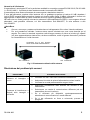
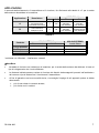
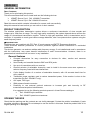
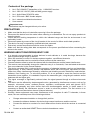
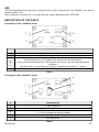
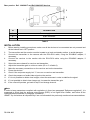
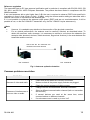
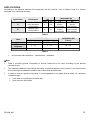
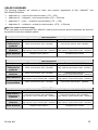
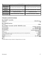
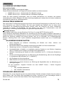
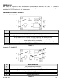
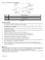
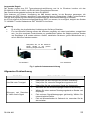
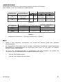
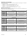
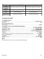
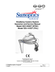
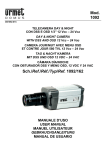
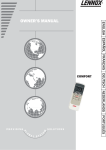
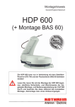
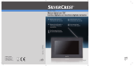
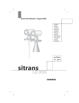
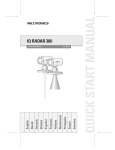
Mod.
1094
DS1094-000
RICEVITORE WIRELESS 2.4GHz
Sch. 1094/001R
TRASMETTITORE WIRELESS 2.4GHz
Sch. 1094/001T
2.4GHz WIRELESS RECEIVER
Ref. 1094/001R
2.4GHz WIRELESS TRANSMITTER
Ref. 1094/001T
2.4GHz FUNKSEMPFÄNGER
RX 1094/001R
2.4GHz FUNKSENDER
TX 1094/001T
MANUALE D’USO
INSTRUCTION MANUAL
Bedienungsanleitung
DS1094-000
1
ITALIANO
INFORMAZIONI GENERALI
Caro cliente
La ringraziamo per l’acquisto di questo prodotto.
Il presente documento descrive come installare ed utilizzare i seguenti dispositivi:
¾
il trasmettitore URMET Domus S.p.A. Sch. 1094/001T
¾
il ricevitore URMET Domus S.p.A. Sch. 1094/001R
Prima di usare le apparecchiature si consiglia di leggere il presente manuale che ne descrive l’uso corretto
e sicuro.
Conservare questo manuale con attenzione ed in un luogo facilmente reperibile per poterlo consultare
prontamente quando necessario.
DESCRIZIONE PRODOTTO
Il sistema di trasmissione audio/video senza fili permette di trasmettere costantemente suoni ed immagini
nitide fino a 100m di distanza in aria libera. L’ottima qualità che riesce a raggiungere il sistema è dovuta
essenzialmente all’utilizzo di un sistema di trasmissione a larga banda. Grazie all’impiego di antenne ad
elevato guadagno, sia in trasmissione che in ricezione, si possono raggiungere buone distanze di
copertura radio anche in presenza di altri sistemi nella medesima banda di frequenza.
eNota Bene
Queste apparecchiature sono conformi alle norme FCC Part-15 e alle direttive Europee R&TTE.
Queste norme indicano le modalità per garantire la protezione contro interferenze dannose in istallazioni
residenziali.
I dispositivi generano, utilizzano e possono irradiare energia a radiofrequenza; se non vengono installati e
utilizzati secondo le istruzioni fornite, possono causare dannose interferenze alle comunicazioni radio.
Tuttavia, non c’è alcuna garanzia che tale interferenza non si verifichino in qualunque installazione.
Caratteristiche generali
¾
Dimensioni compatte per una connessione semplice ad apparati di gestione video, monitor e
telecamere.
¾
Estrema facilità di impiego e versatilità grazie alla presenza dei Jack BNC e RCA.
¾
Uso fino a 4 trasmettitori per un solo ricevitore.
¾
Selettore di canale (4 canali selezionabili) per poter installare nella stessa area più sistemi o
per spostarsi su di una banda di frequenza a minor interferenza.
¾
Funzione di visualizzazione ciclica di un numero di canali selezionabili, con tempo di sosta su
ciascun canale di 4 o 8 secondi.
¾
Regolatore della potenza di trasmissione atta a ridurre la potenza trasmessa nel caso di
ricevitori vicini (solo per Sch. 1094/001T).
¾
Ingressi A/V di tipo RCA.
¾
Connettore d’antenna SMA femmina.
¾
Possibilità di usare antenne esterne opzionali per aumentare la resa e l’immunità alle
interferenze delle trasmissioni/ricezioni RF.
Si consigliano i seguenti prodotti del catalogo Urmet Domus:
•
Antenna a stilo Sch. 1094/050
•
Antenna a pannello Sch. 1094/051
APERTURA DELLA CONFEZIONE
Verificare che l’imballo ed il contenuto non presentino danni visibili. Se alcune parti non sono presenti o
risultano danneggiate, contattare immediatamente il rivenditore.
In questi casi non tentare di utilizzare il dispositivo.
Se il prodotto dovesse essere rimandato al fornitore, assicurarsi di spedirlo con il suo imballo originale.
DS1094-000
2
Contenuto della confezione
¾
N°1 Trasmettitore Sch.1094/001T o N°1 Ricevitore Sch. 1094/001R
¾
N°1 Alimentatore 230V AC 12V DC (300 mA MAX)
¾
N°1 Cavo Audio/Video RCA-RCA
¾
N°1 Adattatore RCA maschio / BNC femmina
¾
N°1 antenna esterna omnidirezionale
¾
Manuale utente
eNota Bene
La composizione degli accessori a corredo può essere variata senza alcun preavviso.
AVVERTENZE GENERALI
¾
¾
¾
¾
¾
¾
¾
Assicurarsi dell’integrità dell’apparecchio dopo averlo tolto dall’imballo.
Prima di effettuare qualsiasi operazione di pulizia o di manutenzione disinserire l’apparecchio dalla
rete di alimentazione elettrica. Pulire le parti esterne metalliche con un panno morbido leggermente
inumidito con sapone delicato e acqua. Non usare prodotti spray per la pulizia dell’apparecchio.
Controllare che la temperatura d’esercizio sia nei limiti indicati e che l’ambiente non sia
particolarmente umido.
In caso di guasto e/o cattivo funzionamento togliere l’alimentazione tramite l’interruttore generale.
Il dispositivo deve essere aperto soltanto da personale tecnico qualificato.
Per le riparazioni rivolgersi solo ad un centro di assistenza tecnica autorizzato.
Prima di collegare l’apparecchio alla rete di alimentazione accertarsi che i dati di targa siano
rispondenti a quelli della rete di distribuzione.
AVVERTENZE RELATIVE ALL’USO DELLA RADIOFREQUENZA
¾
¾
¾
¾
¾
¾
¾
¾
¾
Il posizionamento dei dispositivi in armadi rack o all’interno di strutture metalliche è altamente
sconsigliato, in quanto riduce le distanze di copertura del segnale radio.
Quando si usano due o più sistemi wireless AV insieme, utilizzare canali diversi.
Un unico trasmettitore può essere usato con più ricevitori contemporaneamente.
I selettori di canale permettono di scegliere il canale con le migliori prestazioni e la minor interferenza.
Il ricevitore può cambiare i canali in modo sequenziale ogni 4 o 8 secondi qualora vengono attivati
simultaneamente più canali sul selettore di canale.
Il campo di copertura del dispositivo può diminuire in presenza di ostacoli tra il ricevitore ed il
trasmettitore. Indicativamente una parete divisoria in muratura di 12cm assorbe circa 2db del segnale
che equivale a perdere il 30% della potenza. Molte interferenze dovute a riflessioni e schermature
sono poi create da scaffalature metalliche, radiatori, dai riscaldamenti a pavimento ecc. Per risolvere
questo problema, nel caso in cui non sia possibile avvicinare il ricevitore e il trasmettitore, occorre
migliorare il guadagno sul trasmettitore utilizzando il selettore di guadagno e/o adottando antenne con
un maggior guadagno.
L’attraversamento di solette in cemento armato riduce considerevolmente la copertura del segnale.
Il dispositivo può subire disturbi da fonti di interferenze elettromagnetiche quali ad esempio forni a
microonde, telefoni cordless, ripetitori, router/access point e dispositivi Wi-Fi in genere e in generale
qualsiasi altro dispositivo che possa emettere onde elettromagnetiche. In questi casi è necessario
capire la natura dell’interferenza per porvi rimedio. La prima soluzione è quella di cambiare il canale di
trasmissione dei dispositivi (selettore canale).
Allo stesso modo, queste apparecchiatura possono causare interferenze dannose alla ricezione dei
canali radiotelevisivi; in questi casi l’utente potrà adottare uno dei seguenti accorgimenti:
•
Orientare differentemente o riposizionare le antenne.
•
Aumentare la distanza tra il dispositivo interferente e il ricevitore.
•
Connettere il dispositivo ad una presa su un circuito diverso da quello a cui è collegato il
ricevitore.
•
Consultare un centro di assistenza tecnica autorizzato URMET Domus.
DS1094-000
3
IMPIEGO
Il dispositivo Sch.1094/001R può essere impiegato solo come ricevitore (RX), mentre la Sch.1094/001T
può essere impiegata solo come ricevitore (TX).
Tale impiego consente di poter connettere da 1 a 4 sorgenti video utilizzando un cavo UTP CAT5 dedicato.
DESCRIZIONE DELLE PARTI
Pannello frontale del dispositivo Sch. 1094/001R
1
4
2
3
ID
DESCRIZIONE
1
2
Led di alimentazione
Connettore antenna tipo SMA femmina
Dip-switch per la selezione dei di canale. 1, 2, 3 e 4 indicano il numero di canale.
Se il dip-switch è sulla posizione “ON”, il ricevitore userà quel canale.
Se due o più dip-switch sono su “ON”, il ricevitore userà in sequenza quei canali.
Il tempo di sosta su ciascun canale è 4s o 8s, indicato dalla posizione del dip-switch “T”.
Interruttore ON/OFF
3
4
Tabella 1
Pannello frontale del dispositivo Sch. 1094/001T
4
5
1
3
2
ID
DESCRIZIONE
1
Led di alimentazione
2
4
Connettore antenna tipo SMA femmina
Selettore di canale . Il selettore di canale è un commutatore multifunzione.
1, 2, 3 e 4 indicano il numero di canale.
Interruttore ON/OFF
5
Regolatore del guadagno
3
Tabella 2
DS1094-000
4
Pannello posteriore dei dispositivi Sch. 1094/001T e Sch.1094/001R
2
3
1
ID
DESCRIZIONE
1
Connettore alimentazione
2
Connettore Audio
3
Connettore Video
Tabella 3
INSTALLAZIONE
1.
Prima d’iniziare l’installazione, assicurarsi che tutte le unità da collegare non siano alimentate o che
tutti i pulsanti siano su OFF
2.
Il trasmettitore e il ricevitore devono essere posti su una superficie piana e stabile per evitare
danneggiamenti
3.
Collegare il trasmettitore alla telecamera mediante il cavo RCA-RCA, utilizzando se necessario
l’adattatore RCA/BNC
4.
Collegare il ricevitore al monitor mediante il cavo RCA-RCA, utilizzando se necessario l’adattatore
RCA/BNC
5.
Selezionare il medesimo canale lato ricevitore e trasmettitore
6.
Regolare il guadagno del trasmettitore sul minimo (ID n°5 della tabella 2)
7.
Effettuare i collegamenti necessari sia sul ricevitore che sul trasmettitore
8.
Alimentare i dispositivi
9.
Verificare l’accensione del led rosso di alimentazione “1” sia sul ricevitore che sul trasmettitore
10.
Verificare la presenza del segnale audio/video sul monitor
11.
Nel caso non si riesca a ottenere una corretta visione della scena orientare le antenne in modo da
stabilizzare il segnale
12.
Nel caso non si riesca ancora a ottenere una corretta visione della scena ripresa aumentare il
guadagno lato trasmettitore
13.
Se il disturbo persiste ritornare al passo 5 cambiando canale
eNota Bene
Al fine di mantenere i parametri nei limiti richiesti dalle normative vigenti in materia,(vedi paragrafo
“Normativa di riferimento”) si raccomanda di verificare che la potenza di uscita dall’antenna (EIRP) non sia
superiore a 10dBm e di rispettare tutte le raccomandazioni specificate nel paragrafo “Installazione”.
La società URMET S.p.A non si assume alcuna responsabilità nel caso in cui non vengano rispettate tutte
le raccomandazioni citate in precedenza.
DS1094-000
5
Normativa di riferimento
Il trasmettitore è omologato CE ed in particolare soddisfa le normative europee EN 300 220-2, EN 301 4891 e EN 301 489-3 . Il prodotto è stato testato secondo la normativa EN 60065.
Il trasmettitore deve essere alimentato da una sorgente a bassissima tensione.
È cura dell’utilizzatore, qualora utilizzi antenne con un guadagno superiore al valore di 0 dBi rispettare i
limiti di EIRP impostati dalla normativa vigente nel singolo paese (Italia 10 dBm) utilizzando il trimmer e/o
aggiungendo un attenuatore di valore nominale minore o uguale al guadagno dell’antenna.
Nel caso che non fosse possibile misurare la potenza di uscita dall’antenna (EIRP) e non vengano utilizzati
attenuatori, sarà possibile utilizzare, sul solo trasmettitore Sch.1094/001T, la sola antenna a stilo
Sch.1094/051.
eNota Bene
•
Occorre, comunque, prestare molta attenzione al collegamento fisico che si intende realizzare.
•
Per una prestazione ottimale, l’antenna deve essere orientata con cura come descritto qui di
seguito. Per avere la massima copertura radio bisogna cercare di ridurre al minimo gli ostacoli
(es. altre apparecchiature elettroniche, strutture metalliche, mobili di grosse dimensioni) nell’area
tra il trasmettitore e l’unità ricevente.
Controllare che le due antenne
siano rivolte nella stessa direzione
Sch. 1094/001T
Sch. 1094/001R
Fig.1: Orientamento ottimale delle antenne
Risoluzione dei problemi più comuni
PROBLEMA
Assenza
suono
di
immagine
POSSIBILI SOLUZIONI
e
Presenza di interferenze o
disturbi sulle immagini o
sull’audio
DS1094-000
¾
Verificare che tutti i cavi siano connessi correttamente.
¾
Assicurarsi che tutte le spine di alimentazione siano inserite.
¾
Verificare la corretta presenza delle sorgenti video
¾
Modificare l’orientamento delle antenne del ricevitore e del
trasmettitore
¾
Selezionare un canale di comunicazione differente (sia sul
trasmettitore che sul ricevitore)
¾
Se si utilizzano più dispositivi contemporaneamente,
selezionare le comunicazioni su canali differenti
¾
Se si sta utilizzando un forno a microonde, provare a
spegnerlo.
6
APPLICAZIONI
A seconda della distanza tra il trasmettitore ed il ricevitore, far riferimento alle tabelle 4 e 5 per la scelta
delle antenne da adottare e la casistica.
Distanze (m)
da
a
Applicazione
Descrizione
A
Comunicazione
monodirezionale
trasmettitore/ricevitore
0
100
B
Comunicazione
multipunto-punto
0
80
WIRELESS AV
TX
RX
Antenna a
pannello
Sch.1094/051
Antenna a
pannello
Sch.1094/051
Antenna a
pannello
Sch.1094/051
Antenna stilo
omnidirezionale
Sch.1094/050
Tabella 4
Casistica
Lunga distanza
Medie distanze
Corte distanze
USO IN INTERNO
Rumoroso*
Aria libera
USO IN ESTERNO
in aria libera
10 ÷ 20
15 ÷ 35
60 ÷ 100
5 ÷ 10
5 ÷ 15
35 ÷ 60
0÷5
0÷5
0 ÷ 35
Tabella 5
* ambiente con riflessioni – interferenze- ostacoli
eNota Bene
•
La tabella 4 fornisce una indicazione di massima, per la scelta delle antenne da abbinare in base al
tipo di collegamento che rivuole effettuare.
•
Le distanze indicate possono variare in funzione dei disturbi elettromagnetici presenti nell’ambiente e
del numero e tipo di ostacoli tra il ricevitore ed il trasmettitore.
•
Al fine di garantire una buona qualità visiva, si sconsiglia l’impiego di tali apparati qualora si debba
attraversare:
¾
più di una soletta in cemento armato;
¾
più di due muri in mattoni
DS1094-000
7
SCHEMI DI UTILIZZO
Qui di seguito si riportano alcuni schemi relativi ad applicazioni di base e di uso comune per il dispositivi
Sch.1094/001T e Sch.1094/001R:
¾ applicazione A → comunicazione tipo punto – punto (1TX – 1RX)
¾
applicazione B → comunicazione tipo multipunto – punto (max 4TX – 1RX)
¾
applicazione C → comunicazione tipo punto – multipunto (1TX – ∞RX)
¾
applicazione D → comunicazione tipo multipunto – multipunto (max 4TX – ∞RX)
eNota Bene per uso delle antenne in esterno
Se si utilizzano antenne a pannello del tipo Sch.1094/051 occorre accertarsi che il ricevitore ed il
trasmettitore si trovino il più possibile sullo stesso piano trasmissivo.
Casistica
APPLICAZIONE A
Trasmettitore: Sch.1094/001T
Ricevitore: Sch.1094/001R
Lunga distanza /
problemi
trasmissivi
Antenna a pannello (Sch. 1094/050)
Antenna a pannello (Sch. 1094/050)
Medie distanze
Antenna stilo integrata /
Antenna stilo alta capacità (Sch. 1094/051)
Antenna a pannello /
Antenna stilo alta capacità (Sch. 1094/051)
Corte distanze
Antenna stilo integrata
Antenna stilo integrata
Casistica
APPLICAZIONE B
Trasmettitore: Sch.1094/001T
Ricevitore: Sch.1094/001R
Lunga distanza /
problemi
trasmissivi
Antenna a pannello (Sch. 1094/050)
Antenna stilo alta capacità (Sch. 1094/051)
Medie distanze
Antenna a pannello (Sch. 1094/050)
Antenna stilo integrata /
Antenna stilo alta capacità (Sch. 1094/051)
Corte distanze
Antenna stilo integrata /
Antenna stilo alta capacità (Sch. 1094/051)
Antenna stilo integrata /
Antenna stilo alta capacità (Sch. 1094/051)
Ampiamente
sconsigliato
Antenna a pannello (Sch. 1094/050)
Antenna a pannello (Sch. 1094/050)
Casistica
APPLICAZIONE C
Trasmettitore: Sch.1094/001T
Ricevitore: Sch.1094/001R
Lunga distanza /
problemi
trasmissivi
Antenna a pannello (Sch. 1094/050) /
Antenna stilo alta capacità (Sch. 1094/051)
Antenna a pannello (Sch. 1094/050) /
Antenna stilo alta capacità (Sch. 1094/051)
Medie distanze
Antenna a pannello (Sch. 1094/050) /
Antenna stilo alta capacità (Sch. 1094/051)
Antenna stilo integrata /
Antenna stilo alta capacità (Sch. 1094/051)
Corte distanze
Antenna stilo integrata
Antenna stilo integrata
DS1094-000
8
Casistica
APPLICAZIONE D
Trasmettitore: Sch.1094/001T
Ricevitore: Sch.1094/001R
Lunga distanza /
problemi
trasmissivi
Antenna stilo alta capacità (Sch. 1094/051)
Antenna stilo alta capacità (Sch. 1094/051)
Medie distanze
Antenna stilo integrata /
Antenna stilo alta capacità (Sch. 1094/051)
Antenna stilo alta capacità (Sch. 1094/051)
Corte distanze
Antenna stilo integrata
Antenna stilo integrata
Ampiamente
sconsigliato
Antenna a pannello (Sch. 1094/050)
Antenna a pannello (Sch. 1094/050)
CARATTERISTICHE TECNICHE
Trasmettitore Sch.1094/001T
Potenza di uscita: ................................................................................................................ 10dBm/CE (max.)
Modulazione: ............................................................................................................................................... FM
Ricevitore Sch.1094/001R
Sensibilità: ........................................................................................................................................... -85dBm
Trasmettitore Sch.1094/001T e Ricevitore Sch.1094/001R
Banda di frequenza: ..................................................................................................... 2.400GHz~2.4835GHz
Segnale video in ingresso: .....................................................................................................1Vpp @ 75 ohm
Segnale audio in ingresso: .......................................................................................... max 1Vpp @ 600 ohm
Connettori A/V: ..........................................................................................................................................RCA
Antenna a corredo: ............................................................................................... antenna ominidirezionale)
Alimentazione: ...........................................................................................................................12 Vcc (±10%)
Consumo: ..............................................................................................................................................300mA
Portata in aria libera (priva di riflessioni e interferenze) con dispositivi a vista: ...........................fino a 100m
Temperatura di utilizzo: ...................................................................................................................... -10÷40°c
Umidità : ............................................................................................................................................ 80% max
Dimensioni (L x P x H):........................................................................................................... 56 x 48 x 32mm
Peso: ........................................................................................................................................................ 90 gr
eNota Bene
Le caratteristiche tecniche possono essere soggette a variazione senza alcun preavviso.
DS1094-000
9
ENGLISH
GENERAL INFORMATION
Dear Customer,
Thank you for purchasing this product.
This document describes how to install and use the following devices:
¾
URMET Domus S.p.A. Ref. 1094/001T transmitter
¾
URMET Domus S.p.A. Ref. 1094/001R receiver.
Read this manual which contains information for correct, safe use carefully.
Keep this manual at hand so that you can refer to it when needed.
PRODUCT DESCRIPTION
The wireless audio/video transmission system allows a continuous transmission of clear sounds and
images up to 100m free air range. The very high quality reached by the system depends above all from the
usage of a broad band transmission system. Thanks to high gain antennas, both in transmission and in
reception, it is possible to reach good radio coverage distances, also if are present other systems using the
same frequency band.
eImportant note
These devices are compliant with FCC Part-15 requirements and R&TTE Europeans directives.
These directives describe procedures to ensure protection against harmful interference in residential
installations.
The devices generate, use and can radiate radio frequency energy; if not installed and used in accordance
with the instructions, may cause harmful interference to radio communications. However, there is no
guarantee that interference will not occur in any installation.
General features
¾
Compact dimensions for easy connection to devices for video, monitor and cameras
management.
¾
User-friendly and versatile thanks to BNC and RCA jacks.
¾
Use up to 4 transmitters with one receiver.
¾
Channel selector (4 selectable channels), used to install in the same area more systems or
select a frequency band with less interference.
¾
Cyclic display function of a number of selectable channels, with 4-8 seconds dwell time for
every channel.
¾
Transmitter power regulator used to reduce transmitted power, if the receiver is close to the
transmitter (for Ref. 1094/001T only).
¾
A/V inputs, RCA type.
¾
SMA antenna female connector.
¾
Possibility to use external optional antennas to increase gain and immunity to RF
transmissions/receptions interferences.
It is suggested to use the following products present in Urmet Domus catalogue:
•
Ref. 1094/050 stylus antenna.
•
Ref. 1094/051 panel mount antenna.
OPENING THE BOX
Check that the packing and the contents are not visibly damaged. Contact the retailer immediately if parts
are either missing or damaged. Do not attempt to use the device in this case. Send the product back in its
original packing if it is damaged.
DS1094-000
10
Contents of the package
¾
No.1 Ref. 1094/001T transmitter or No. 1 1094/001R receiver.
¾
No.1 230V AC 12V DC (300 mA MAX) power supply
¾
No.1 Audio/Video RCA-RCA cable
¾
No.1 RCA male / BNC female adapter
¾
No.1 external omnidirectional antenna
¾
User manual
eImportant note
Accessories may be changed without prior notice.
PRECAUTIONS
¾
¾
¾
¾
¾
¾
¾
Make sure that the device is intact after removing it from the package.
Disconnect the device from the mains before cleaning or maintenance. Do not use spray products to
clean the device.
Check that the working temperature is within the indicated range and that the environment is not
particularly humid.
Disconnect power by means of the circuit breaker in the event of a failure and/or bad operation.
The device can only be opened by qualified technical personnel.
Exclusively contact an authorised service centre for repairs.
Make sure that the rating plate data corresponds to the power specifications before connecting the
device to the mains.
WARNING ABOUT RADIOFREQUENCY USE
¾
¾
¾
¾
¾
¾
¾
¾
¾
It is strongly unrecommended to place devices in rack cabinets or in metal housings, because the
radio signal coverage range is reduced.
When are used two or more AV wireless systems together, use different channels.
One single transmitter can be used with several receivers at the same time.
Channel selectors allow to select the channel with the best features and the lowest interference.
The receiver can sequentially change the channels every 4 or 8 seconds, if are activated at the same
time more channels on the channel selector.
The device coverage field is reduced by the presence of obstacles between receiver and transmitter.
Approximately, a 12cm masonry partition wall absorbs about 2db of the signal, equivalent to a 30%
power loss. Many interferences caused by reflection and shielding are also created by metal shelves,
radiators, floor heating, etc. To solve this problem, if it is not possible to move the receiver and the
transmitter closer together, it is needed to improve the transmitter gain, using the gain selector and/or
antennas with an higher gain.
The signal coverage is significantly reduced when the signal passes through a reinforced-concrete
slab.
The device can be affected by electromagnetic noise, generated by interference sources, such as, for
example, microwave ovens, cordless phones, repeaters, router/access point and generic Wi-Fi
devices, and generally any other device that emit electromagnetic waves. In these cases it is
necessary to identify the interference source in order to solve the problem. The first solution is to
change the device transmission channel (channel selector).
Similarly, these equipments can cause interference to the reception of radio TV channels; in these
cases, the user can adopt one of the following solutions:
•
Change antennas orientation or change their position.
•
Increase the distance between the device that causes interference and the receiver.
•
Connect the device to a socket of a circuit different from that to which the receiver is connected
to.
•
Contact an authorized URMET Domus technical assistance centre.
DS1094-000
11
USE
The Ref.1094/001R device can only be used as receiver (RX), while the Ref. Sch.1094/001T can only be
used as receiver (TX).
This use allows to connect from 1 to 4 video sources, using a dedicated CAT5 UTP cable.
DESCRIPTION OF THE PARTS
Front panel or Ref. 1094/001R device
1
4
2
3
ID
DESCRIPTION
1
2
Power supply led
SMA female antenna connector
Dip-switch for channel selection. 1, 2, 3 and 4 indicate the channel number.
If the dip-switch is in “ON” position, the receiver will use that channel.
If two or more dip-switches are in “ON” position, the receiver will use those channels in
sequence.
The dwell time on every channel is 4s or 8s, indicated by dip-switch “T” position.
ON/OFF switch
3
4
Table 1
Front panel or Ref. 1094/001T device
4
5
1
3
2
ID
DESCRIPTION
1
2
Power supply led
SMA female antenna connector
Channel selector . The channel selector is a multifunction switch.
1, 2, 3 and 4 indicate the channel number.
ON/OFF switch
Gain adjustment
3
4
5
Table 2
DS1094-000
12
Rear panel or Ref. 1094/001T and Ref.1094/001R devices
2
3
1
ID
DESCRIPTION
1
2
3
Power supply connector
Audio connector
Video connector
Table 3
INSTALLATION
1.
Before starting installing procedures, make sure all the devices to be connected are not powered and
all the buttons are in OFF position.
2.
The transmitter and the receiver must be located on a level and steady surface, to avoid damages.
3.
Connect the transmitter to the camera with the RCA-RCA cable, using the RCA/BNC adapter, if
necessary.
4.
Connect the receiver to the monitor with the RCA-RCA cable, using the RCA/BNC adapter, if
necessary.
5.
Select the same channel for receiver and transmitter.
6.
Adjust the transmitter gain to minimum value (ID no. 5 of table 2).
7.
Make the necessary connections on the receiver and on the transmitter.
8.
Power the devices.
9.
Check if the red power supply led “1” turns on on receiver and transmitter.
10.
Check the presence of audio/video signal on the monitor.
11.
If it is not possible to obtain clear images, orient the antennas in order to stabilize the signal.
12.
If it not possible to obtain clear images yet, increase the transmitter gain.
13.
If the noise still persists, go back to step 5 and change channel.
eNote
In order to keep parameters compliant with regulations in force (see paragraph “Reference regulation”), it is
suggested to check that the antenna output power (EIRP) is not higher than 10dBm, and follow all the
recommendations detailed in paragraph “Installation”.
URMET S.p.A disclaims all responsibility if are not followed all the previously mentioned recommendations.
DS1094-000
13
Reference regulation
The transmitter has an EC type approval certification and in particular is compliant with EN 300 220-2, EN
301 489-1 and EN 301 489-3 European Standards. The product has been tested in compliance with EN
60065 standards.
If are used antennas with a gain higher than 0 dB, the user is required to observe EIRP limits specified in
regulations in force in that country (in Italy, 10 dBm), using the trimmer and/or adding an attenuator with a
nominal value lower or equivalent to the antenna gain.
If it is not possible to measure the antenna output power (EIRP) and are not used attenuators, it will be
possible to use, on the Ref. 1094/001T transmitter only, the Ref. 1094/051 stylus antenna only.
eNote
•
However, it is needed to pay attention to the execution of the physical connection.
•
For an optimal performance, the antenna must be carefully oriented, as described below. To
obtain the maximum radio coverage, it is necessary to reduce to a minimum the obstacles (for
example other electronic devices, metal structures, large-sized furniture) in the area between the
transmitter and the receiver.
Check that the two antennas are
oriented in the same direction
Ref. 1094/001T
Ref. 1094/001R
Fig.1: Antennas optimal orientation
Common problems resolution
PROBLEM
Absence of video and audio
Presence of interferences or
noise on video or audio
DS1094-000
POSSIBLE SOLUTIONS
¾
Check that all the cables are correctly connected.
¾
Make sure that all the power supply sockets are plugged.
¾
Check the correct presence of video sources.
¾
Change receiver and transmitter antennas orientation.
¾
Select a different communication channel (both on transmitter
and receiver)
¾
If several devices are used at the same time, select
communications on different channels.
¾
If a microwave oven is used, try to turn it off.
14
APPLICATIONS
According to the distance between the transmitter and the receiver, refer to tables 4 and 5 to choose
antennas to be used and the case.
Distances
(m)
from
to
Application
Description
A
Transmitter/receiver
mono-directional
communication
0
100
B
Multipoint-point
communication
0
80
WIRELESS AV
TX
RX
Panel mount
antenna
Ref.1094/051
Panel mount
antenna
Ref.1094/051
Panel mount
antenna
Ref.1094/051
Omni-directional
stylus antenna
Ref.1094/050
Table 4
Case
Long distance
Medium
distances
Short distances
Noisy*
INDOOR USE
Free air
OUTDOOR USE
Free air
10 ÷ 20
15 ÷ 35
60 ÷ 100
5 ÷ 10
5 ÷ 15
35 ÷ 60
0÷5
0÷5
0 ÷ 35
Table 5
•
environment with reflections – interferences – obstacles.
eNote
•
Table 4 provides general information to choose antennas to be used, according to the desired
connection type.
•
The indicated distances can change according to electromagnetic noise present in the environment
and number/type of obstacles between the receiver and the transmitter.
•
In order to ensure a good visual quality, it is not suggested to use these devices when it is necessary
to pass through:
¾
more than one reinforced-concrete slab;
¾
more than two brick walls.
DS1094-000
15
USAGE DIAGRAMS
The following diagrams are referred to basic and common applications of Ref. 1094/001T and
Ref.1094/001R devices.
¾ application A → point-to-point communication (1TX – 1RX)
¾
application B → multipoint – point communication (4TX – 1RX max)
¾
application C → point – multipoint communication (1TX – ∞RX)
¾
application D → multipoint – multipoint communication (4TX – ∞RX max)
eNote for outdoor antenna usage
If are used panel mount antennas Ref. 1094/051, make sure the receiver and the transmitter are as much
as possible on the same radiation pattern.
Case
APPLICATION A
Transmitter: Ref.1094/001T
Receiver: Ref.1094/001R
Long distance /
Transmission
problems
Panel mount antenna (Ref. 1094/050)
Panel mount antenna (Ref. 1094/050)
Medium
distances
Integrated stylus antenna /
High capacity stylus antenna (Ref . 1094/051)
Integrated stylus antenna /
High capacity stylus antenna (Ref . 1094/051)
Short distances
Integrated stylus antenna
Integrated stylus antenna
Case
APPLICATION B
Transmitter: Ref.1094/001T
Receiver: Ref.1094/001R
Long distance /
Transmission
problems
Panel mount antenna (Ref. 1094/050)
High capacity stylus antenna (Ref . 1094/051)
Medium
distances
Panel mount antenna (Ref. 1094/050)
Integrated stylus antenna /
High capacity stylus antenna (Ref . 1094/051)
Short distances
Integrated stylus antenna /
High capacity stylus antenna (Ref . 1094/051)
Integrated stylus antenna /
High capacity stylus antenna (Ref . 1094/051)
Absolutely not
recommended
Panel mount antenna (Ref . 1094/050)
Panel mount antenna (Ref . 1094/050)
Case
APPLICATION C
Transmitter: Ref.1094/001T
Receiver: Ref.1094/001R
Long distance /
Transmission
problems
Panel mount antenna (Ref. 1094/050) /
High capacity stylus antenna (Ref . 1094/051)
Panel mount antenna (Ref. 1094/050) /
High capacity stylus antenna (Ref . 1094/051)
Medium
distances
Panel mount antenna (Ref. 1094/050) /
High capacity stylus antenna (Ref . 1094/051)
Integrated stylus antenna /
High capacity stylus antenna (Ref . 1094/051)
Short distances
Integrated stylus antenna
Integrated stylus antenna
DS1094-000
16
Case
APPLICATION D
Transmitter: Ref.1094/001T
Receiver: Ref.1094/001R
Long distance /
Transmission
problems
High capacity stylus antenna (Ref . 1094/051)
High capacity stylus antenna (Ref . 1094/051)
Medium
distances
Integrated stylus antenna /
High capacity stylus antenna (Ref . 1094/051)
High capacity stylus antenna (Ref . 1094/051)
Short distances
Integrated stylus antenna
Integrated stylus antenna
Absolutely not
recommended
Panel mount antenna (Ref . 1094/050)
Panel mount antenna (Ref . 1094/050)
TECHNICAL SPECIFICATIONS
Ref. 1094/001T transmitter
Output power: ...................................................................................................................... 10dBm/CE (max.)
Modulation: .................................................................................................................................................. FM
Ref. 1094/001R receiver
Sensitivity: ........................................................................................................................................... -85dBm
Ref. 1094/001T transmitter and Ref. 1094/001R receiver
Frequency band:........................................................................................................... 2.400GHz~2.4835GHz
Input video signal:...................................................................................................................1Vpp @ 75 ohm
Input audio signal: ....................................................................................................... max 1Vpp @ 600 ohm
A/V connectors: .........................................................................................................................................RCA
Provided antenna: .................................................................................................omnidirectional antenna )
Power: .......................................................................................................................................12 Vcc (±10%)
Consumption: ........................................................................................................................................300mA
Free air range (without reflections and interferences) with line of sight devices ............................up to 100m
Working temperature range:............................................................................................................... -10÷40°c
Humidity:............................................................................................................................................ 80% max
Dimensions (W x D x H): ........................................................................................................ 56 x 48 x 32mm
Weight: ..................................................................................................................................................... 90 gr
eNote
Technical features may be subject to change without prior notice.
DS1094-000
17
DEUTSCH
ALLGEMEINE INFORMATIONEN
Sehr geehrter Kunde,
Danke, dass Sie dieses Produkt gekauft haben.
Dieses Dokument beschreibt, wie folgende Produkte installiert und benutzt werden:
¾
URMET Domus S.p.A. / Grothe GmbH TX 1094/001T Sender
¾
URMET Domus S.p.A. / Grothe GmbH RX 1094/001R Empfänger.
Lesen Sie diese Anleitung aufmerksam, denn sie enthält Informationen zur korrekten und sicheren
Verwendung der Geräte. Bewahren Sie diese Anleitung sorgfältig auf, sodass Ihnen die darin enthaltenen
Informationen jederzeit zur Verfügung stehen.
PRODUKTBESCHREIBUNG
Das Audio/Video Funkübertragungssystem erlaubt die kontinuierliche Übertragung von Bild und Ton bis zu
einer Reichweite von 100m im Freifeld. Die sehr gute Qualität des Systems wird vor allem durch
Verwendung von Breitband-Funkkomponenten erreicht. Dank der Antennen mit hoher Verstärkung,
verwendet im Sender und Empfänger, hat das System eine sehr gute Funkreichweite, auch bei
gleichzeitiger Verwendung anderer Systeme im gleichen Frequenzbereich.
eWichtiger Hinweis
Diese Geräte sind konform mit den Richtlinien FCC Part-15 und der R&TTE-Richtlinie der EU.
Diese Richtlinien beschreiben Maßnahmen zur Einhaltung des Schutzes gegen schädliche Störungen im
häuslichen Bereich. Die Geräte generieren, benutzen und emittieren Hochfrequenzstrahlung; Falls sie nicht
gemäß der Anleitung installiert und benutzt werden, kann es zu Störungen von Funkübertragungen
kommen. Allerdings kann nicht in jeder Installation ausgeschlossen werden, dass es zu Funkstörungen
kommt.
ALLGEMEINE EIGENSCHAFTEN
¾
¾
Kleine Baugröße zur einfachen Verwendung mit Geräten zum Video-, Monitor- und
Kameramanagement.
Benutzerfreundliche und vielseitige Verwendung dank BNC und Chinch Anschlüssen
¾
Benutzung von bis zu 4 Sendern mit einem Empfänger.
¾
Kanalwahlschalter (4 Kanäle), zur Installation mehrerer Systeme in der Gleichen Umgebung
oder zur Auswahl einer Frequenz mit weniger Störungsbelastung.
¾
Zyklische Umschaltung der Kanäle mit einer Umschaltzeit von 4 o. 8 Sekunden Schaltzeit je
Kanal.
¾
Sender mit Leistungsregulierung zur Reduzierung der Sendeleistung, falls sich der Empfänger
in unmittelbarer Nähe befindet (nur TX 1094/001T).
¾
A/V-Eingänge mit Chinch-Anschluss
¾
SMA Antenne mit Female-Stecker (Buchse)
¾
Verwendung von externen Antennen zur Erhöhung der Signalstärke bzw. zur Minimierung von
Störungen möglich.
Es wird empfohlen, folgende Produkte aus dem URMET Domus / Grothe Programm
zu verwenden:
•
ANT 1094/050 Stabantenne
•
ANT 1094/051 Flachantenne.
ÖFFNEN DER VERPACKUNG
Überprüfen Sie, ob die Verpackung oder der Inhalt sichtbare Schäden aufweist. Wenden Sie sich sofort an
Ihren Händler, falls Teile fehlen oder beschädigt sein sollten. Versuchen Si nicht, beschädigte Geräte in
Betrieb zu nehmen. Senden Sie diese Geräte in ihrer Originalverpackung zurück.
DS1094-000
18
Packungsinhalt
¾
1 Stk. TX 1094/001T Sender oder RX 1094/001R Empfänger.
¾
1 Stk. 230V AC 12V DC (300 mA MAX) Netzgerät.
¾
1 Stk. Audio/Video Chinch-Leitung
¾
1 Stk. Adapter Chinch-Stecker auf BNC Buchse
¾
1 Stk. externe omnidirektionale Antenne
¾
Bedienungsanleitung
eWichtiger Hinweis
Zubehör kann sich ohne vorherige Ankündigung ändern.
VORSICHTSMASSNAHMEN
¾
¾
¾
¾
¾
¾
¾
Stellen Sie sicher, dass die Geräte intakt sind, nachdem sie aus der Verpackung genommen wurden.
Trennen Sie das Gerät vom Netz, bevor Si es reinigen oder warten. Benutzen kein Spray zum
Säubern des Gerätes.
Überprüfen Sie, dass sich die Betriebstemperatur im angegebenen Bereich befindet und dass in der
Betriebsumgebung keine spezielle Feuchtigkeit vorhanden ist.
Schalten Sie die Spannung mit Hilfe des Leitungsschutzschalters ab, sollte ein Fehler oder eine
Fehlfunktion auftreten.
Das Gerät ist nur vom dafür autorisierten, technischen Personal zu öffnen.
Wenden Sie sich an den Händler oder den Kundenservice des Herstellers
Stellen Sie sicher, das die Netzspannung mit den Spannungsangaben auf dem Typenschild
übereinstimmen bevor Sie das Gerät mit der Netzspannung verbinden.
WARNUNGEN BEZÜGLICH FUNKVERBINDUNG
¾
¾
¾
¾
¾
¾
¾
¾
¾
Es wird unter keinen Umständen empfohlen, das Gerät in einen Metallschrank oder ein Metallgerüst
zu platzieren. Dieses reduziert die Signalreichweite.
Beide der Verwendung von mehreren A/V-Funksystemen benutzen Sie unterschiedliche Kanäle.
Ein einzelner Sender kann gleichzeitig mit mehreren Empfängern betrieben werden.
Der Kanalwahlschalter erlaubt die Auswahl des Kanals mit besten Eigenschaften und wenigsten
Störungen.
Der Empfänger kann die Kanäle alle 4 oder 8 Sekunden sequenziell umschalten, wenn gleichzeitig
mehrere Kanäle am Empfänger aktiviert werden.
Die Funkreichweite des Systems wird durch Objekte zwischen Sender und Empfänger reduziert. Ein
12cm dickes Mauerwerk absorbiert ca. 2dB des Signals und damit ca. 30% der Sendeleistung. Viele
Störungen werden durch Reflexionen oder Abschirmung durch Metallteile erzeugt, wie z.B.
Metallregale, Radiatoren, Heizung. Falls es nicht möglich ist, den Sender und Empfänger näher
zusammen zu bringen, kann die Verwendung von externen Antennen mit höherer Verstärkung u. U.
das Problem lösen.
Die Funkreichweite wird signifikant reduziert, falls das Signal eine armierte Betondecke passieren
muss.
Das Gerät kann durch elektromagnetische Störungen, wie z.B. Mikrowellengrill, schnurlose Telefone,
WI-FI-Router, Repeater oder andere Geräte die elektromagnetische Felder ausstrahlen, beeinflusst
werden. In diesem Fall ist es nötig die Störquelle zu identifizieren um das Problem zu lösen. Die erste
Aktion ist den Kanal der Funkübertragung zu wechseln (Kanalwahlschalter).
Gleichzeitig ist es nicht ausgeschlossen, dass dieses Gerät u.U. Störungen in anderen Geräten
hervorruft. In diesem Fall kann der Benutzer folgende Vorgehensweise verwenden:
•
Wechseln der Antennenausrichtung oder der Antennenposition.
•
Vergrößerung des Abstandes zwischen Gerät und Sender/Empfänger.
•
Wechseln der Phase (L1-L3)
störenden/gestörten Gerät.
•
Nehmen Sie Kontakt zu Ihrem Händler oder dem Kundenservice des Herstellers auf.
DS1094-000
der
Spannungsversorgung,
unterschiedlich
zum
19
GEBRAUCH
Das Gerät RX 1094/001R kann ausschließlich als Empfänger, während das Gerät TX 1094/001T
ausschließlich als Sender benutzt werden kann. Diese Vorgehensweise erlaubt die Verwendung einer
speziellen CAT5-UTP-Leitung für 1-4 Videoquellen.
BSCHREIBUNG DER GERÄTE
Frontseite RX 1094/001R
1
4
2
3
ID
BESCHREIBUNG
1
2
LED Netzspannungsversorgung
SMA Buchse Antennenverbindung
DIP-Schalter zur Kanalauswahl. 1, 2, 3 und 4 bezeichnen die Kanalnummer.
Ist der Schalter in “ON” Position, wird der Empfänger den Kanal benutzen.
Sind zwei oder mehr Kanäle in “ON” Position, wird der Empfänger
diese Kanäle zyklisch umschalten.
Die Schaltzeit jedes Kanals beträgt 4s oder 8s, je nach Stellung des Schalters “T”.
EIN (ON) / Aus (OFF) Schalter
3
4
Tabelle 1
Frontseite TX 1094/001T
4
5
1
3
2
ID
BESCHREIBUNG
1
2
LED Netzspannungsversorgung
SMA Buchse Antennenverbindung
Kanalwahlschalter. Der Schalter ist ein Multifunktionsschalter
Position 1, 2, 3 und 4 Bezeichnet die gewählte Kanalnummer.
Ein(ON) / Aus(OFF) Schalter
Verstärkungsanpassung
3
4
5
Tabelle 2
DS1094-000
20
Rückseite TX 1094/001T and RX1094/001R
2
3
1
ID
BESCHREIBUNG
1
2
3
Steckverbindung Spannungsversorgung
Audio Stecker
Video Stecker
Tabelle 3
INSTALLATION
1.
Bevor Sie mit der Installation beginnen, stellen Sie sicher, das alle Geräte nicht Spannungsversorgt
sind und alle Schalter sich in AUS (OFF) Position befinden.
2.
Der Sender und der Empfänger müssen auf einer flachen, stabilen Ebene montiert werden, um
Beschädigungen zu vermeiden.
3.
Verbinden Sie den Sender mit der Kamera. Benutzen Sie dazu die CHINCH-Leitung und ggf. den
Adapterstecker zu BNC.
4.
Verbinden Sie den Empfänger mit dem Monitor. Benutzen Sie dazu die CHINCH-Leitung und ggf.
den Adapterstecker zu BNC.
5.
Wählen Sie den gleichen Kanal am Sender und Empfänger aus.
6.
Stellen Sie den Sender auf minimale Sendeleistung (ID no. 5 in Tabelle 2).
7.
Führen Sie alle nötigen Verbindungen des Senders und des Empfängers aus
8.
Schalten Sie die Spannungsversorgung und die Geräte ein.
9.
Überprüfen Sie, ob die LED „1“ an Sender und Empfänger leuchtet.
10.
Überprüfen Sie das vorhandene Audio-/Videosignal am Monitor.
11.
Falls es nicht möglich ist, ein stabiles Bild zu erhalten, Richten Sie die Antennen des Senders und
des Empfängers aus, um das Signal zu stabilisieren.
12.
Falls es nicht möglich ist ein klares Bild zu erhalten, erhöhen Sie die Verstärkung des Senders.
13.
Falls die Störungen noch immer anhalten, gehen Sie zu Punkt 5 der Installationsprozedur und
wechseln Sie den Kanal.
eAchtung
Um die Parameter des Systems konform mit den in Kraft befindlichen Regularien zu halten (siehe Abschnitt
“Angewandte Regeln”) wird empfohlen zu prüfen, ob die Ausgangsleistung der Antenne (EIRP) nicht
größer als 10 dBm ist und alle Empfehlungen im Abschnitt “Installation” befolgt werden.
URMET S.p.A/Grothe GmbH lehnt jegliche Verantwortung aller Art ab, falls den zuvor erwähnten
Empfehlungen nicht Folge geleistet wird.
DS1094-000
21
Angewandte Regeln
Der Sender besitzt eine EG Typenzulassung/-zertifizierung und ist im Einzelnen konform mit den
EN 300 220-2, EN 301 489-1 und EN 301 489-3 europäischen Normen.
Das Produkt wurde getestet konform der Norm EN 600065.
Falls Antennen mit höherer Verstärkung als 0dB benutzt werden, ist der Benutzer gezwungen, die
Einhaltung der EIRP Grenzen, spezifiziert in den geltenden Normen (Deutschland, 10dBm), sicherzustellen
und ggf. eine Anpassung oder Dämpfung entsprechend der Antennenverstärkung zu benutzen.
Ist es nicht möglich die Antennenausgangsleistung (EIRP) zu messen, ist es möglich, lediglich den Sender
TX 1904/001T und die Stabantenne ANT 1094/051 zu benutzen.
eAchtung
•
Es ist nötig, der physikalischen Verbindung der Geräte zu Beachten.
•
Für eine optimale Leistung müssen die Antennen sorgfältig, wie unten beschrieben, ausgerichtet
sein. Um eine maximale Funkreichweite zu gewährleisten sollten die Objekte zwischen Sender
und Empfänger (z.B. andere elektron. Geräte, metallische Strukturen, große Möbelstücke etc..)
auf ein Minimum reduziert werden.
Überprüfen Sie, ob die Antennen
beider Geräte in die gleiche
Richtung ausgerichtet sind
TX 1094/001T
RX 1094/001R
Fig.1: optimale Antennenausrichtung
Allgemeine Problemlösung
PROBLEM
MÖGLICHE URSACHE
¾
Kein Bild- oder Tonsignal
Störungen und Rauschen
im Video-/Audio-Signal
DS1094-000
Überprüfen Sie alle Leitungen auf korrekte Verbindung.
¾
Überprüfen Sie, dass alle Netzgeräte eingesteckt sind.
¾
Überprüfen Sie das vorhandene Signal der Videoquelle.
¾
Wechseln Sie die Sender/Empfänger Antennenausrichtung.
¾
Wählen Sie einen anderen Übertragungskanal an Sender und
Empfänger
¾
Falls mehrere Signalübertragungen gleichzeitig: Wählen Sie
unterschiedliche Kanäle.
¾
Falls ein Mikrowellenherd in Gebrauch ist, versuchen Sie ihn
abzuschalten.
22
ANWENDUNGEN
Entsprechend der Entfernung und Anwendung zwischen Sender und Empfänger,
siehe Tabellen 4 und 5 zur Auswahl der richtigen Antenne.
Entfernung
(m)
from
to
ANWENDUNG
BESCHREIBUNG
A
Sender/Empfänger
Punkt-zu-Punkt
Verbindung
0
B
Multipunkt Verbindung
0
FUNKÜBERTRAGUNBG AV
TX
RX
100
Flachantenne
ANT 1094/051
Flachantenne
ANT 1094/051
80
Flachantenne
ANT.1094/051
Stabantenne
ANT.1094/050
Tabelle 4
ENTFERNUNG
FERN
MITTEL
KURZ
INNEN ANWENDUNG
GESTÖRT*
FREILUFT
AUSSEN ANWENDUNG
FREILUFT
10 ÷ 20
15 ÷ 35
60 ÷ 100
5 ÷ 10
5 ÷ 15
35 ÷ 60
0÷5
0÷5
0 ÷ 35
Tabelle 5
•
Umgebung mit Reflexionen – Störungen (Interferenzen) - Objekten.
eNote
•
Tabelle 4 liefert allgemeine Informationen zur Auswahl der Antenne gemäß dem gewählten
Verbindungstypus
•
Die angegebenen Reichweiten können variieren entsprechend auftretender elektromagnetischer
Störeinflüsse im Umgebungsbereich der Übertragung oder Anzahl, Art und Größe von Objekten
zwischen Sender und Empfänger.
•
Um eine gute Übertragungsqualität zu gewährleisten wird nicht empfohlen die Geräte dort
einzusetzen, wo eine Übertragung durch folgende Örtlichkeiten nötig ist:
•
mehr als eine Stahlbetondecke
•
mehr als zwei Ziegelstein/Klinker Wände
DS1094-000
23
BENUTZUNG / APPLIKATIONEN
Die folgenden Darstellungen sind bezogen auf einfache und allgemeine Anwendungen für TX 1094/001T
und RX 1094/001R Geräte.
¾ Applikation A → Punkt-zu-Punkt Kommunikation(1TX – 1RX)
¾
Applikation B → Multipunkt - Punkt Kommunikation (4TX – 1RX max)
¾
Applikation C → Punkt - Multipunkt Kommunikation (1TX – x RX)
¾
Applikation D → Multipunkt – Multipunkt Kommunikation (4TX – x RX max)
eBeachte für Außenanwendungen
Falls Flachantennen ANT 1094/050 benutzt werden, stellen Sie sicher, dass Sender und Empfänger soweit
möglich die gleiche Abstrahlungscharakteristik haben.
FALL
APPLIKATION A
Transmitter: TX1094/001T
Receiver: RX1094/001R
FERN/
Transmissions
probleme
Flachantenne ANT 1094/050
Flachantenne ANT 1094/050
MITTEL
Integrierte Stabantenne /
High capacity Stabantenne ANT 1094/051
Integrierte Stabantenne /
High capacity Stabantenne ANT 1094/051
KURZ
Integrierte Stabantenne
Integrierte Stabantenne
FALL
APPLIKATION B
Transmitter: TX 1094/001T
Receiver: RX 1094/001R
FERN/
Transmissions
probleme
Flachantenne ANT 1094/050
High capacity Stabantenne ANT 1094/051
MITTEL
Flachantenne ANT 1094/050
Integrierte Stabantenne /
High capacity Stabantenne ANT 1094/051
KURZ
Integrierte Stabantenne /
High capacity Stabantenne ANT 1094/051
Integrierte Stabantenne /
High capacity Stabantenne ANT 1094/051)
Absolut nicht
empfehlenswert
Flachantenne ANT 1094/050
Flachantenne ANT 1094/050
FALL
APPLIKATION C
Transmitter: TX1094/001T
Receiver: RX 1094/001R
FERN/
Transmissions
probleme
Flachantenne ANT 1094/050 /
High capacity Stabantenne ANT 1094/051
Flachantenne ANT 1094/050/
High capacity Stabantenne ANT 1094/051
MITTEL
Flachantenne ANT 1094/050/
High capacity Stabantenne ANT 1094/051
Integrated stylus antenna /
High capacity Stabantenne ANT 1094/051
KURZ
Integrierte Stabantenne
Integrierte Stabantenne
DS1094-000
24
APPLIKATION D
Transmitter: Ref.1094/001T
FALL
Receiver: Ref.1094/001R
FERN/
Transmissions
probleme
High capacity Stabantenne ANT 1094/051
High capacity Stabantenne ANT 1094/051
MITTEL
Integrierte Stabantenne
High capacity Stabantenne ANT 1094/051
High capacity Stabantenne ANT 1094/051
KURZ
Integrierte Stabantenne
Integrierte Stabantenne
Absolut nicht
empfehlenswert
Flachantenne ANT 1094/050
Flachantenne ANT 1094/050
TECHNISCHE DATEN
TX 1094/001T Sender
Ausgangsleistung: ............................................................................................................... 10dBm/CE (max.)
Modulation: .................................................................................................................................................. FM
RX 1094/001R Empfänger
Empfindlichkeit: ................................................................................................................................... -85dBm
TX 1094/001T Sender und RX1094/001R Empfänger
Frequenzband: ............................................................................................................. 2.400GHz~2.4835GHz
Eingang Video Signal: ........................................................................................................... 1Vpp @ 75 Ohm
Eingang Audio Signal: .................................................................................................max 1Vpp @ 600 Ohm
A/V Stecker:............................................................................................................................. CHINCH (RCA)
Mitgelieferte Antenne:......................................................................................... omnidirektionale Antenne )
Spannung: .................................................................................................................................12 Vcc (±10%)
Verbrauch: .............................................................................................................................................300mA
Freiluftreichweite (ohne Reflexionen und Störungen) mit Sichtverbindung der Geräte ............... bis zu 100m
Betriebstemperaturbereich: ................................................................................................................ -10÷40°c
Feuchtigkeit: ...................................................................................................................................... 80% max
Maße (W x D x H):.................................................................................................................. 56 x 48 x 32mm
Gewicht:..................................................................................................................................................... 90 g
eNote
Technische Daten können sich ohne vorherige Ankündigung ändern.
DS1094-000
25
Technische Änderungen vorbehalten!
Grothe GmbH
Löhestraße 22
53773 Hennef
Telefon:
Telefax:
E-Mail:
Internet:
(0 22 42) 88 90-0
(0 22 42) 88 90-36
[email protected]
www.grothe.de
Der Hersteller haftet in keiner Weise für Schäden, die durch einen unsachgemäßen
Gebrauch der in dieser Bedienungsanleitung beschriebenen Geräte entstehen. Des
weiteren behält sich der Hersteller das Recht vor, den Inhalt dieser Anleitung ohne
vorherige Benachrichtigung zu ändern.
Die in dieser Bedienungsanleitung enthaltenen Ausführungen sind sorgfältig
ausgearbeitet und überprüft worden, trotzdem übernimmt der Hersteller keinerlei
Verantwortung für die Verwendung derselben. Dasselbe gilt für die Personen oder Firmen,
die zur Ausarbeitung und Erstellung dieser Anleitung hinzugezogen wurden.
DS1094-000
Prodotto in Cina su specifica URMET Domus
Made in China to URMET Domus specification
FILIALI
20151 MILANO – V.Gallarate 218
Tel. 02.380.111.75 - Fax 02.380.111.80
00043 CIAMPINO (ROMA) V.L.Einaudi 17/19A
Tel. 06.791.07.30 - Fax 06.791.48.97
80013 CASALNUOVO (NA) V.Nazionale delle Puglie 3
Tel. 081.193.661.20 - Fax 081.193.661.04
30030 VIGONOVO (VE) – V.del Lavoro 71
Tel. 049.738.63.00 r.a. - Fax 049.738.63.11
66020 S.GIOVANNI TEATINO (CH) – V.Nenni 17
loc. Sambuceto Tel. 085.44.64.851
Tel. 085.44.64.033 - Fax 085.44.61.862
SEDE
DS1094-000
URMET DOMUS S.p.A.
10154 TORINO (ITALY)
VIA BOLOGNA 188/C
Telef.
+39 011.24.00.000 (RIC.AUT.)
Fax
+39 011.24.00.300 - 323
Area Tecnica
Servizio Clienti +39 011.23.39.810
http://www.urmetdomus.com
e-mail: [email protected]
26