1
PLANNING THE WIRING
ENGLISH
All System wiring should be installed to meet the appropriate parts of BS5839-8 (1998), BS
EN 60849 (1998) and BS 7671 (Wiring Regulations). Other national standards of installation
should be adhered to where applicable.
To comply with EMC (Electro Magnetic Compatibility) regulations and to reduce the risk of electrical
interference in the system wiring, we recommend the use of fire-resistant (screened for signals)
cables throughout the installation.
All wiring should come into the enclosure via the knockouts provided and be fixed tidily to the relevant
terminals. For an overview of the connections required for the fire alarm interface, loudspeakers,
fireman’s microphone, paging/background music equipment and slave amplifiers, please refer to
the relevant sections later in this manual (see Contents on page 31).
Note that correct cable glanding is essential and due regard should be paid to any system
specifications which demand a certain cable type (providing it meets the appropriate national wiring
regulations).
MOUNTING THE SE5120/SE5121
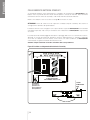
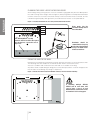
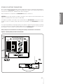
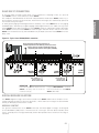
The SE5120/SE5121’s enclosure can be surface or semi-flush mounted (see page 40). It comprises
a hinged metal lid and metal back box containing all of the system’s electronics. To protect the
electronics against damage during first fix installation, all of the SE5120/SE5121’s PCBs (apart from its
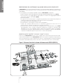
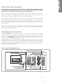
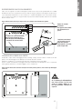
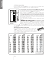
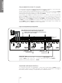
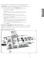
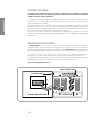
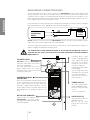
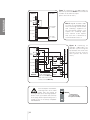
lid mounted Indicator PCB) are located on a removable chassis plate, as shown in Figure 1 below.
The enclosure must be sited internally in an area not subject to conditions likely to affect its
performance, e.g. damp, salt-air, water ingress, extremes of temperature, physical abuse, etc.
It should be positioned at a height where it is easily accessible and in a prominent position within the
building. Ideally, the indicators on the front of the enclosure should be at eye level.
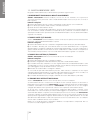
Figure 1 : The SE5120/SE5121 Enclosure
CHASSIS EARTH STRAP
LID EARTH STRAP
PL2
INDICATOR
PCB
AMPLIFIER
PCB
DIGITAL
Message
Store
PCB
PL1
PL6
LID/BASE CONNECTING CABLES
38
MAIN
PCB
PL5
CHASSIS PLATE
POWER
SUPPLY
PCB