1
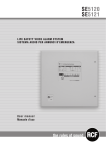
ZoneSense PLUS
Fire Alarm Control Panel
EN54 2 & 4 1997
Installation, Commissioning &
Operation
MAN 2326-12
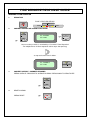
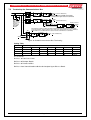
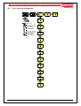
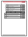
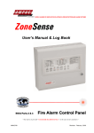
FIRE BRIGADE RESPONSE GUIDE
INCOMING ALARM CONDITION
1.
INDICATION
ZONE 7 FIRE LED STEADY
FIRE
FIRE
2.
ZONE 7
ZONE 8
SOUNDER SILENCE OR SOUND EVACUATION
ALARMS
SILENCE
RESOUND
Z7 : ALARM
SU 14:45
EVACUATE
Access to these controls is restricted by a Password / Panel Keyswitch
For multiple Zones in Alarm repeat the above steps after pressing.
to step to the next Zone in Alarm.
Z7 : DISABLE
SU 14 46
3.
SOUNDER SILENCE / SOUNDER RESOUND
PRESS SILENCE / RESOUND TO SILENCE ALARMS. PRESS AGAIN TO REACTIVATE.
ALARMS
4.
DISABLED
SILENCE
RESOUND
RESET
RESET ALARMS
PRESS RESET
TABLE OF CONTENTS
1
2
About This Manual ............................................................................................................... 1
1.1
Purpose ..................................................................................................................... 1
1.2
Scope ........................................................................................................................ 1
1.3
References................................................................................................................. 1
Introduction .......................................................................................................................... 2
2.1
3
Features..................................................................................................................... 2
Mechanical............................................................................................................................ 3
3.1
4
Page No.
Mounting the Enclosure .............................................................................................. 3
3.1.1
Fixing the Chassis to the Wall ......................................................................... 3
3.1.2
PCB Removal / Replacement.......................................................................... 6
3.1.3
Removing the Knockouts ................................................................................ 7
Electrical ............................................................................................................................... 8
4.1
Primary Power Supply ................................................................................................ 8
4.1.1
Mains wiring ................................................................................................... 8
4.1.2
Connecting the Panel...................................................................................... 8
4.1.3
Installing the Power Supply PCB..................................................................... 8
4.1.4
Connecting the Mains ..................................................................................... 8
4.2
Battery Charger .......................................................................................................... 9
4.3
Secondary Supply ...................................................................................................... 9
4.3.1
Connecting the Stand-By Batteries ............................................................... 10
4.4
Cable Types and Limitations .................................................................................... 10
4.5
Powering Up the Panel ............................................................................................. 10
5
Main Control Card BRD25MCB –A (4 Zone) B (8 Zone) .................................................... 11
6
Wiring to the Main Card BRD25MCB ................................................................................. 13
6.1
Earth Monitoring ....................................................................................................... 13
6.2
Communications ...................................................................................................... 13
6.3
TB3 Inputs................................................................................................................ 14
6.4
Zones....................................................................................................................... 14
6.4.1
Detector Interface ......................................................................................... 14
6.4.2
Detector Configuration .................................................................................. 14
6.4.3
Detector Removal Facility ............................................................................. 14
6.5
Zone Circuit Wiring TB13 - 14................................................................................... 15
6.6
Monitored Alarms Outputs ........................................................................................ 15
6.7
Conventional Sounder Circuit Wiring ........................................................................ 16
6.7.1
6.8
6.9
Outputs –Monitored Modified Open Collector TB5 .................................................... 16
6.8.1
Alarm Output TB5 1/2 ................................................................................... 16
6.8.2
Fault Output TB5 3/4 .................................................................................... 16
Outputs – Volt Free Relay Programmable................................................................. 16
6.9.1
6.10
Sounder Loading and Distribution ................................................................. 16
Ancillary Output TB5 5/6/7 ............................................................................ 16
Outputs – Volt Free Relay Non-Programmable ......................................................... 17
6.10.1
Fault Output TB5 8/9/10 .............................................................................. 17
6.10.2
Auxiliary Power Output TB12 1/2 ................................................................ 17
6.10.3
Buzzer ........................................................................................................ 17
6.10.4
7
Reset Terminal / Buzzer Output. TB12/3 ..................................................... 17
Adding Control and Monitoring Facilities ......................................................................... 18
7.1
Internal Communications Connector (RS485) ........................................................... 18
7.2
Installation and Cabling of Add On Cards & Boards .................................................. 18
7.3
Terminating the Communications Bus ...................................................................... 19
8
Internal Terminal Block Numbering Quick Reference ...................................................... 20
9
Status and Programming Screens..................................................................................... 21
10
9.1
Level 1 to 3 Status Screens ...................................................................................... 21
9.2
Level 2 Test Screens................................................................................................ 22
9.3
Level 2 Disable Screens ........................................................................................... 22
9.4
Level 3 System Programming ................................................................................... 23
9.5
Level 3 Programming Menu...................................................................................... 24
List of Compatible Devices ................................................................................................ 25
10.1
Item Numbers .......................................................................................................... 26
11
Glossary of Terms .............................................................................................................. 27
12
Definitions .......................................................................................................................... 28
13
Battery Capacity Calculation ............................................................................................. 29
14
Trouble Shooting Chart...................................................................................................... 32
15
Installation and Commissioning Report ............................................................................ 33
15.1
Procedure ................................................................................................................ 34
15.2
System Information .................................................................................................. 34
16
Statement of Compliance................................................................................................... 37
17
Installation Details.............................................................................................................. 39
18
Certification Information .................................................................................................... 40
19
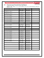
Commissioning Of Installed Cards And Boards ............................................................... 41
20
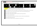
EN54 ABS Inner Front Panel Configuration Labelling ...................................................... 42
21
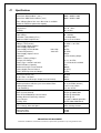
Specifications ..................................................................................................................... 43
ZONESENSE PLUS INSTALLATION, COMMISSIONING & OPERATION
1
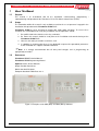
About This Manual
1.1
Purpose
This manual is an instructional tool for the installation, commissioning, programming /
reprogramming and operation of the ZoneSense PLUS Fire Alarm Control Panel (FACP).
1.2
Scope
The information within this manual is only available to and for the use of personnel engaged in the
installation and operation of the ZoneSense PLUS FACP.
ZoneSense PLUS has been designed to comply with major world standards. To ensure these
standards are not compromised in any way installation staff and operators should;
1. Be qualified and trained for the task/s they undertake;
2. Be aware this manual should be read prior to the installation and commissioning of the
ZoneSense PLUS FACP;
3. Observe anti-static pre-cautions at all times; and
4. If a problem is encountered or there is any doubt with respect to the operational parameters
of the installation the supplier should be contacted.
Note: It is strongly recommended that all front panel changes and or programming be
appropriately recorded.
1.3
References
ZoneSense PLUS Technical Manual
ZoneSense PLUS Programming Manual
Apollo Detector / Device Manuals
Ampac Product Data Sheets
British Standard: BS 5839
European Standard: EN54 Parts 2 & 4
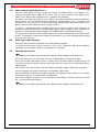
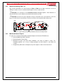
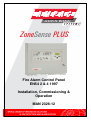
Figure 1: Examples of the ABS (BX1) and Metal (BX10) Cabinets
Page 1
ZONESENSE PLUS INSTALLATION, COMMISSIONING & OPERATION
2
Introduction
The ZoneSense PLUS 4, 8 zone FACP complies with the highest level of approval for any
applicable code and can be connected to an appropriate Fire Service monitoring facility.
As a Minimum, the conventional panel meets the following Standards;
British Standard
European Standard
BS 5839
EN54 Parts 2 & 4
The basic ZoneSense PLUS is available in a ABS (BX1) and Metal (BX10) cabinets and consists of
a;
1. Main PCB, with all controls and indicators mounted directly onto it; and
2. A switch-mode power supply;
3. 2 X 12 Volt batteries connected in series.
4. 2 X ABS and / or 003 keys
Note: Only devices compatible with ZoneSense PLUS should be used in an installation. These
are listed in this document.
2.1
Features
The front panel 8 x 2 line LCD, navigation keys and the Menu/Enter keys allow
the ZoneSense PLUS to be programmed ˆon site˜. The same LCD and keys are also used
for panel operation and interrogation.
Four monitored “Alarms” outputs.
Two optional auxiliary input connections.
Two current limited outputs (Fire [alarm] and Fault).
Two relay outputs (ancillary and fault).
Optional external buzzer or reset output.
System expansion capabilities / options:
Keyswitch/password entry to a wide range of engineering functions which include;
1. Selectable zone delay;
2. Zone test;
3. Coincidence ( double-knock );
4. Non-latching zones;
5. Comprehensive fault diagnostics;
A wide range of secure user functions. This includes the ability to disable/enable a large
number of system functions.
An “Alarm Time” feature is standard on all panels.
Flush or surface mountable enclosure. A surround is required for the metal cabinet
Controls have tactile and audible feedback of operation.
All terminals cater for 2.5mm cables.
Page 2
ZONESENSE PLUS INSTALLATION, COMMISSIONING & OPERATION
3
Mechanical
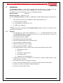
ZoneSense PLUS can be surface or semi-flush mounted. The ABS version is supplied with a
detachable door, a mountable back box. Depending on the configuration it may be necessary to
remove the batteries to expose the lower mounting keyhole.
All of which are easily removed should it be necessary.
Inside the door is a matrix style label for the recording of the panel configuration.
3.1
Mounting the Enclosure
The panel MUST be mounted in an area that is NOT subject to conditions likely to affect its
performance, e.g. damp, salt-air, water ingress, extremes of temperature, abuse etc. is at an easily
accessible height and such that the indicators are at eye level.
3.1.1
Fixing the Chassis to the Wall
Taking into account the total weight of the panel and batteries securely mount the panel.
The ABS (BX1) uses three keyhole mounting holes
The Metal Cabinet (BX10) uses two keyhole and two standard mounting holes
Use suitably sized screws and plugs for the type of mounting surface.
Mounting is best achieved by positioning the box against the surface it is to be mounted to, marking
the holes, taking the box well away from the surface and then drilling the holes.
Caution: Any dust or swarf created during the fixing process must be kept out of the cabinet and
great care should be taken not to damage any wiring or components.
TO REMOVE FRONT DOOR
LIFT THE DOOR UP
OFF THE HINGES
BRIDGE
ASSEMBLY
REMOVING
KNOCKOUTS
ABS KEY SLOTS
POWER
SUPPLY
NOTE: BATTERY TRAY SITS HERE IN THE BOTTOM OF THE CABINET
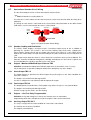
Figure 2: Explode and Assembled View for the ABS Model FACP Note: The Metal Cabinet (BX10) is
assembled in the same fashion
The BX1 front door is locked by way of two clips on the right hand side of the cabinet. A special
locating key which has two raised pins that are inserted into the side of the cabinet unlocks the door.
The BX1 can also be supplied with a 003 Key Lock if required. The BX10 box is locked with a 003
Key.
AM
PA
C
DOOR RELEASE PINS
Figure 3: Plastic Key
Page 3
DOOR RELEASE PINS
ZONESENSE PLUS INSTALLATION, COMMISSIONING & OPERATION
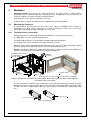
163.20 mm
147.00 mm
147.00 mm
Figure 4: ABS cabinet (BX1) Mounting Points
Page 4
ZONESENSE PLUS INSTALLATION, COMMISSIONING & OPERATION
230.90 mm
288.40 mm
Figure 5: Metal Cabinet (BX10) Mounting Points
Legend: PCB Mounting Screws
Bridge Mounting Holes
Either Side of Bridge
PCB
Terminal Blocks
ABS Bridge
Figure 6: Exploded Front View of Membrane, Bridge and PCB for the ABS Model
Key Switch Mechanism
Mounting Screws
Terminal Blocks
PCB
ABS Plastic Bridge
LCD
Front Membrane
Figure 7: Exploded Top View of Membrane, Bridge and PCB
Page 5
ZONESENSE PLUS INSTALLATION, COMMISSIONING & OPERATION
3.1.2
PCB Removal / Replacement
If the PCB’s have to be removed the following precautions should be observed;
1. Removing the door will provide better access to the boards and ensure the hinges are not
accidentally stressed.
2. Personal anti- static procedures must be followed.
3. When disconnecting the telecom style (RJ45) connecting cable from the PCB, make sure
that the cable remains connected to at least one board to prevent it being misplaced.
Connector
Push Tab Inwards
and Gently Pull
the Connector
From the Socket
Figure 8: RJ45 Connector
Note: Care should be taken when detaching this connector as it is necessary to depress the
small locking tab to unlock the connector from its base. To reconnect the cable the connector must
first be correctly aligned then pushed into the socket so it locks into position.
1. Carefully remove the retaining screws at each corner of the board taking care not to damage
any of the components.
2. Place each board into anti- static storage once removed.
Page 6
ZONESENSE PLUS INSTALLATION, COMMISSIONING & OPERATION
3.1.3
Removing the Knockouts
Carefully decide how the wiring will be brought into the panel then remove the required knock-outs
for the bushes and cables.
The knock-outs should be removed with a sharp tap in the rim of the knock-out using a flat broadbladed screwdriver. Use of excessive force could damage the enclosure around the knock-out.
Always ensure if a knock-out is removed, the hole is filled with a good quality cable gland. Any
unused knock-outs must be securely blanked off.
REMOVING
KNOCKOUTS
Figure 9: Knockout Removal
Page 7
ZONESENSE PLUS INSTALLATION, COMMISSIONING & OPERATION
4
Electrical
4.1
Primary Power Supply
The Power Supply is;
A switch-mode design and operates from a mains supply of: 90VAC - 264VAC @ 47Hz 63Hz;
Capable of supplying the system while all zones are in alarm; and
4.1.1
Mains wiring
The requirement for the Mains supply to the FACP is fixed wiring, using three core cable (no less
than 0.75mm² and no more than 2.5mm² ) or a suitable three conductor system, fed from an
isolating switch fuse spur, fused at 3A. This should be secured from unauthorised operation and be
marked 'FIRE ALARM: DO NOT SWITCH OFF. The Mains supply must be exclusive to the FACP.
4.1.2
Connecting the Panel
Connecting ZoneSense PLUS internal connections and PCBs is best undertaken immediately prior
to Commissioning.
Before beginning ensure all devices on the circuits are correctly connected and that cable integrity is
verified throughout the installation
Important: DO NOT use an insulation tester ('Megger') with any electronic devices
connected. Faults occurring in the wiring which are not picked up at this stage will almost certainly
result in spurious and intermittent faults when the equipment is energised.
4.1.3
Installing the Power Supply PCB
ZoneSense PLUS Power Supply PCB combines the functions of a Mains to DC switched mode
power supply unit, battery charging unit and battery monitoring unit.
Important: Under no circumstances should the ZoneSense PLUS panel be operated
without the Power Supply PCB correctly mounted in the enclosure and the retaining screws securely
tightened.
4.1.4
Connecting the Mains
The technician should NOT attempt to connect Mains to the Panel until fully conversant with the
layout and features of the Power Supply PCB.
The incoming Mains cable should be brought into the Panel at the top right hand side of the
enclosure and correctly terminated on the Chassis Earth Terminal and then to the Power Supply
connector block.
Note: Fuse F1 (2Amp Supply 1.25 Amp / 250VAC M205) (3 Amp Supply 2Amp /
250VAC M205) is field replaceable
Before switching on the Power Supply the Earth MUST be connected to the chassis earth terminal.
1. All earth cabling must be terminated to the Panel Chassis Earth Terminal in a Star
configuration.
2. The earth cable closest to the cabinet body must have an M4 SPW beneath the lug then an
M4 SPW and M4 nut.
3. Each additional earth cable must be terminated with an M4 SPW and M4 nut.
4. An additional M4 nut and M4SPW are fitted to the earth terminal for installers to connect the
mains earth
Page 8
ZONESENSE PLUS INSTALLATION, COMMISSIONING & OPERATION
Chassis Earth Terminal
Note:
* Extra M4 Nut and M4 SPW are
provided finger tight on the Earth bolt.
M4 Nut *
M4 Shake Proof Washer *
Earth Cable
Earth Cable
Figure 10: Chassis Earth Terminal Connection
4.2
Battery Charger
The battery charger is an integral part of the Power Supply and is capable of;
Recharging standard sized system batteries within 24 hours;
Detecting a missing, damaged or undercharged battery;
Protecting the battery against reverse or a short circuit condition;
Charging batteries in line with Sealed Lead Acid battery manufacturers’ circuit temperature
compensation guidelines.
Note: Battery disconnect has been incorporated to prevent the battery from discharging
through the battery charger should the charging voltage be less than the battery voltage.
(AC IN)
N
PROTECTIVE PERSPEX
COVER
CHASSIS EARTH
TERMINAL
See Specifications
for correct fuse value
EARTH ( GREEN )
ACTIVE ( BROWN )
NEUTRAL ( BLUE )
A TB1 Fuse
DANGER
O
N
O
F
F
NOTE: MAINS CABLE
SHOULD BE NO LESS
THAN 0.75mm
LED: AC ON
NOTE: 3 AMP
is not fitted with this LED
and uses the Indicator within
the switch
METAL
COVER
DC OUTPUT
1 2 3
12
DC ON
LED
OV +27V GND
-BATT+
Battery 1
12 Volts
- + +
Battery 2
12Volts
27V TO THE MAIN CARD
Figure 11: Power Supply Battery Charger Wiring
4.3
Secondary Supply
In the event of a mains failure the backup battery is capable of maintaining the quiescent condition
for 72 hours as well as full alarm load for a further period of 30 minutes.
Note: Any power supply fault to be indicated within 1 hour.
Page 9
ZONESENSE PLUS INSTALLATION, COMMISSIONING & OPERATION
4.3.1
Connecting the Stand-By Batteries
Two new, good quality and fully charged 12V Sealed Lead Acid batteries are required as the
emergency stand-by power supply for the Panel. They are to be mounted in the bottom of the
cabinet. In the ABS version a protective tray is supplied in the packaging.
The batteries should be connected in series using the series link wire provided and located within the
panel enclosure. The red and black battery leads from the Power Supply ( CN 3 ) should be run to
the batteries in such a way there is no risk of them being damaged then, connect the red wire to the
positive terminal and the black wire to the negative terminal .
The panel's sophisticated battery monitoring protects the batteries against deep discharge by
activating a cut off circuit when the stand-by supply voltage reaches approx 21 volts. If batteries are
not fitted, are discharged or in poor condition, the “POWER FAULT “LED will be illuminated.
The capacity of the batteries to be installed depends on the panel configuration and required standby time. To calculate the required AH capacity of the batteries refer to the calculation guide located
in the rear of this manual.
4.4
Cable Types and Limitations
All System wiring should be installed to meet national wiring regulations.
To shield the Panel from outside interference and ensure compliance with Electro Magnetic
regulations screened cables can be used throughout an installation.
4.5
Powering Up the Panel
Note: It is not recommended to connect the batteries before applying mains power first.
Ensure that the panel is free from swarf, wire ends, knockout blanks and any other debris
Ensure that all cable connections to zones, sounder circuits and other inputs or outputs being used
are correct and that the wiring is formed neatly away from the surface of the circuit boards before
applying power.
Connect the mains, and turn on the Panel by switching the power supply switch to the on position.
Check the polarity of the battery connections carefully before proceeding.
Connect the batteries together first by fitting the battery link (typically a white cable) to a +ve terminal
of one battery and to a –ve terminal of the second battery.
Connect the red battery lead to the +ve terminal of the second battery and the black battery lead to
the –ve terminal of the other battery.
Note: It is not recommended to connect the batteries before applying mains power first.
Page 10
ZONESENSE PLUS INSTALLATION, COMMISSIONING & OPERATION
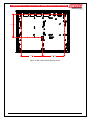
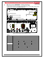
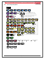
Main Control Card BRD25MCB –A (4 Zone) B (8 Zone)
The Main Control Card and its front display panel combined with the Power Supply / Battery Charger
/ batteries form the basis for the ZoneSense PLUS FACP.
TP37
TP39 TP36
TP35
TP34
TP33
TP60
TP61
TP31 TP30
TP32
T P59
TP58
TP24
TP23
-
TP22
TP21
TP20
-
+
-
+
TP19
+
TP18
TP17
-
TP16
TP14
TP15
TP13
TP12
TP11
TP10
TP9
TP8
TP7
TP6
TP5
T P4
TP3
TP2
+3-
+1-
+2-
2
1
TP29
TP28
+Z8-
+Z6-
+Z7-
+Z5-
+Z4-
+Z3-
+Z2-
3
+Z1-
C
COMMS
+4-
TP25
INPUTS
+ -
TP26
ZONES
+ -
OUTPUTS
TP 1 to 44
( See the Terminal Block
Quick Reference for Detail )
TP27
T P1
+
MON.
TP40
-
EARTH
DISABLE
+
CN5: Comms To
Internal Boards
CN1: The Link is inserted when the
Front Panel Keyswitch is not used
REV._1
Keyswitch
Link
CN1
CN9: To Any Cards
Fitted To The Front Panel
CN8: 27V From the Power Supply
Cutout
CN10: 27V to the Internal Modules
CN10
CN6: Monitoring Comms from the Power Supply
+ -
ALARMS 1 - 4
ZONES
TB13
TB14
+Z1- +Z2- +Z3- +Z4- +Z5- +Z6- +Z7- +Z8-
COM SP C/C ALT
FIRE FLT
TB4
+1-
ANC
+2- +3-
+4-
T B12
D5
D22
D6
D7
D8
D9
RL3
C
D4
+ ///
D3
D20
C
D2
RL2
NO NC
D18
///
NO NC
D11
24VDC RST
+ A - + F - NO C NC NO C NC
Fire
D31
FLT
TB5
OUT PUTS
T B3
MON.
OUTPUTS
EARTH
DISABLE
INPUTS
T B2
ZONES
R22
COMMS
INPUTS
K1
BOTTOM OVERLAY
D19
Ancillary Output Disabled
Power
CN 2
D29
D12
D21
Alarms / Fault Disabled
Power Fault
D16
D13
System Fault
D38
Test
D14
D24
LCD
D23
D25
Fault Output Fault Disabled
Earth Fault
D37
Fault / Disabled / Test
D15
Alarms Status
Fire Output On
SW9
U2
Q20
REV._1
CN8
COMMS
U3
D28
D26
D10
D27
D17
TOP OVERLAY
U1
SW8
Delay
Alarms
Fire
Silence
Resound
Silence
Buzzer
U18
CN7
+
Override
SW1
U4
SW2
SW3
Fault
Disabled
Reset
Evacuate
SW4
SW5
SW12
Menu
Enter
U6
BZ1
SW10
FUSE:5A.
SW11
X1
U12
SW6
FS1
SW7
Cancel
U19
5
Figure 12: Main Control Card Top and Bottom Layout
Cabling
Connector
CN1
CN2
CN3 & 4
CN5
Pins
CN6
Pins
CN7
CN8
Pins
CN9
Pins
CN10
Purpose /Pins
Link pins 1 & 2 when the front panel keyswitch is NOT used.
LCD Driver
LCD Back Lighting
Comms and +/- 27VDC to the front panel cards.
1 & 8 = 0V
2 & 7 +27VDC 3 & 4 = RS 485 Bus,
5 = Tx. Enable
Monitoring / Comms from the Power Supply.
1 & 8 = 0V
2 = PSU Sense
3 = PSU Adjust
4 = Charger ON
5 = Batt Load
6 = Temp sense
7 = Batt V Sense.
Factory Use Only
+/- 27VDC and earth from the Power Supply / Charger.
1 = 0V
2 = +27VDC
3 = Earth
Comms to the internal back plane boards.
Pin connections are the same as CN5
1 +27VDC and 2 0V to the internal back plane boards
Page 11
INPUTS
RS485
COM SP C/C ALT
TB3
-
TB2
+
S
P
A
R
E
Class Change
Input
EOL
Capacitor
Rear of Main Board
CN6 PSU Control from CN2 of the P/S
CN8:27V In from CN4 of the P/S
CN10: 27V Out to Internal Cards & Boards
TB14
+ Z5 - + Z6 - + Z7 - + Z8 -
DETECTOR ZONES
Open Collector O/Ps Current Limited to
25mA. and Detector Removal Facility Available
TB13
+ Z1 - + Z2 - + Z3 - + Z4 -
ALL Un-used Zones MUST be Terminated in an EOL
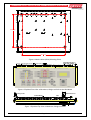
Power Supply Main Board Internal Wiring
Comms
Link
LAM,
8 Way Remote
Relay Board
Note: Comms Link
is required when
only one Systems
Comms board is used
Alert
Input
Maximum of 32
Devices per Zone
+1
-
EOL
Resistor
TB4
- +3
1
-
FAULT
+
Monitored
Current Limited
25mA O/P's
FIRE
+
FAULT
N/O C N/C
Voltage Free
Contacts 1A/30V
ANCILLARY
TB5
N/O C N/C
7
5
3
1
CN5
2
8
6 CN2
4
2
OV +27V GND
1 2 3
DC OUTPUT
CN4
-BATT+
TB2
Power Supply Unit ( BRD25PSUA )
-
O/P's
EOL Resistor
Required
- RST
12v Batt
- -
12v Batt
24VDC OUT
Monitored
24V 500mA
O/P
TB12
+
+24v / 100mA
3 Sec
Reset
0v Pulse
Front of Main Board Illustrated External Cabling
EOL
Resistor
- +4
EOL
Resistor
4 X Monitored
Alarms Outputs
Maximium
500mA / 24V
+2
EOL
Resistor
+
Page 12
+
EOL Termination Values
Zone
=
10uf,3K3, 4K7,
6K8 or 10Kohms
Monitored O/P's =
10Kohms
ZONESENSE PLUS INSTALLATION, COMMISSIONING & OPERATION
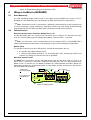
ZONESENSE PLUS INSTALLATION, COMMISSIONING & OPERATION
Figure 13: Simple Wiring Diagram of the Basic FACP
6
Wiring to the Main Card BRD25MCB
6.1
Earth Monitoring
The earth monitoring disable/enable feature is accessible via the SYSTEM menu at access level 3.
Disabling the earth monitoring does not illuminate the Earth Fault LED on the control panel.
Note: If ZoneSense PLUS is connected to a third party system which has earth monitoring and
its earth monitoring is being affected by ZoneSense PLUS even after being disabled through
programming the resistor R22 on the Main Card in ZoneSense PLUS can be removed.
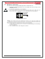
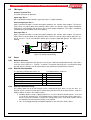
Communications
External Communications Terminals (RS485) TB2 1, 2 & 3
The RS 485 output drives the remote cards and mimics up to a distance of 1.2km from the panel
itself. The external cabling (2x2 shielded pair plus power) is wired to TB2 +, - and earth.
Note: If a fault occurs on the communications bus the common FAULT and SYSTEM FAULT
LED’S are illuminated and the details can be displayed on the LCD by selecting the Faults Menu.
Remote Cards
The number of cards that can be installed on the external communications bus are:
8 x Remote Zone Mimic Indicator Cards
1 x Remote Relay Board. provides 8 sets of normally open (NO), normally closed (NC) and
Common (C) voltage free contacts rated at 1A @ 30VDC.
Main Card Comms Link K1
LK1 MUST be inserted when only the front door panel cards and the Main Card are used as an
FACP. If this is not the case and TB2 is cabled to LED Repeaters and / or 8 Way Remote Relay
Boards a link is inserted in the last board to complete the communication circuit or if boards are
mounted on the back pan and communications are wired from the Main Card then the last board in
this chain MUST be terminated.
Shield
To LAM's and/or
Remote Relay Boards
K1
+
Note: the shield is
wired to
RS485
TB2
Figure 14: Wiring Detail
Page 13
Inputs
Comms Link
Top Left Hand Corner
of the Main Board
Class Change I/P
Alert I/P
Spare I/P
Comms
6.2
SP C/C ALT
Com
1
TB3
2
3
ZONESENSE PLUS INSTALLATION, COMMISSIONING & OPERATION
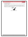
6.3
TB3 Inputs
Common Terminal TB3
Used with the inputs 0v potential.
Spare Input TB3 /1
Not used (Monitored input defaults to general alarm as explained below).
Class Change Input TB3 / 2
Input is provided to allow a remote connection to operate the sounder alarm outputs. The input is
active when it is pulled down to 0v potential. When active the sounder alarms output will operate
continuously, no indication shall be given and no other output will operate. This input is monitored,
(monitoring may be disabled) and is non-latching.
Alert Input TB3 / 3
Input is provided to allow a remote connection to operate the sounder alarm outputs. The input is
active when it is pulled down to 0v potential. When active the sounder alarm outputs will pulse at a
rate of 1sec on 1 sec off, no indication shall be given, no other output will operate. This input is nonlatching
TB3
Class
Change
Input
COM
Spare
Alert
Input
C/C
ALT
Figure 15: Auxiliary Input Wiring
6.4
Zones
6.4.1
Detector Interface
All zones will be programmed to operate in one of the 6 different configuration modes each with a
reset time in the order of > 1 second < 2 seconds. To maintain “back up “times a maximum of thirty
two (40) 24V fire detectors can be connected to each 24mA current limited zone interface.
6.4.2
Detector Configuration
The operating configuration modes are,
Normal
AVF
Non Latching
Agent Trigger 1
Agent Trigger 2
Double Knock
6.4.3
LCD abbreviations shown are;
=
=
=
=
=
=
Normal
AVF
No Latch
Agent T1
Agent T2
Dbl Knck
Detector Removal Facility
This facility allows for up to 20 detectors to be removed from their bases at any one time. If a
detector head is removed a fault will be indicated on that zone and all the other devices retain the
ability to initiate an alarm. This facility requires;
Schottky diodes having a voltage drop of 0.2 – 0.3 of a volt to be installed across L1 in and
L1 out on the detector base. The limitation on the number of heads that can be removed is a
direct result of the cumulative effect of the voltage drop across each diode. Diodes will not
be required if the head removal facility is not required.
The use and programming of a bipolar capacitor as the end of line (EOL) device.
Page 14
ZONESENSE PLUS INSTALLATION, COMMISSIONING & OPERATION
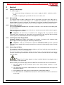
6.5
Zone Circuit Wiring TB13 - 14
Zone circuit connections are made directly to TB13 & TB14 on the Main Card and if screened
cabling is used the screen is terminated at the panel's chassis earth terminal.
Reminder 1: A maximum of 32 ZoneSense PLUS compatible Optical / Heat Detectors or
Manual Call Points can be fitted to each circuit and mixed in any order.
Reminder 2: An End of Line Capacitor must be connected across the terminals of the last
device on each circuit. Unused Zones must have an End of Line capacitor fitted at the panel.
MAIN
PCB
L1 In
TB
13
&
14
-R
APOLLO STANDARD
BASE WIRING
L1 In
+
APOLLO SERIES 60 DIODE
BASE WIRING
-R
L1 In
-R
+
+
L1 Out
L1
Out
-
Earth
L2
-
Earth
L2
-
EOL
Earth
L2
The diode is used when the detector removal facility is utilised
Figure 16: Typical Detector Wiring with Detector Removal Facility Diodes
6.6
Monitored Alarms Outputs
The panel has 4 dedicated individually monitored outputs terminated to TB4 which are;
Rated at 500mA @ 24VDC nominal;
Protected against short circuits;
Monitored for open and short circuit conditions even when an output is active. The
monitoring operates on a reverse voltage principal and will indicate a fault within 60
seconds.
Programming which zones will operate any of the outputs is done via the front Panel.
Page 15
ZONESENSE PLUS INSTALLATION, COMMISSIONING & OPERATION
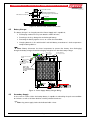
6.7
Conventional Sounder Circuit Wiring
The four alarm outputs can be used for conventional sounder circuits.
Note: All Sounders must be polarised.
An end of line resistor (10kΩ) must be connected at the end of each circuit to allow the wiring to be
monitored.
The wiring for each circuit is connected to the relevant 5mm connector block on the Main Control
PCB and the screens terminated to the chassis earth terminal.
Sounder 2
Sounder 1
FACP
Alarm
Output
+
-
Sounder 3
X
E
O
L
X
DO NOT SPUR
Figure 17: Typical Sounder Circuit Wiring
6.7.1
Sounder Loading and Distribution
The FACP's Power Supply is designed to give a maximum output current of 2A. In addition to
powering the sounders, this current is also used for handling short circuit faults, supplying the
Panel's battery charging circuit and any output relays that may be fitted. As a safe margin and to
allow for these other loads, the total sounder loading for the panel should not exceed a maximum of
1.5A.
Each Output and or Sounder circuit is current limited to a maximum alarm current of 500mA. The
Sounders should be distributed throughout the building according to the sound levels required, and
the load distributed as equally as possible across each circuit.
6.8
Outputs –Monitored Modified Open Collector TB5
Definition: A monitored modified open collector output for user connections such as a relay.
Via the front panel it is possible to program which zones will operate any of the outputs.
6.8.1
Alarm Output TB5 1/2
The output operates in parallel to the Alarm Output relay and energises in the alarm condition of a
zone that is isolated.
The output is current limited to 25mA @ 27VDC.
If a zone is configured as non-latching it will not operate this output.
6.8.2
Fault Output TB5 3/4
The output operates in parallel to the Fault Output relay and de-energises in any fault condition.
The output is current limited to 25mA @ 27VDC.
All faults except “System Faults” are non-latching.
6.9
Outputs – Volt Free Relay Programmable
Definition: A relay with voltage free change over contacts for user connections.
Programming which zones will operate any of the outputs is done via the front Panel.
6.9.1
Ancillary Output TB5 5/6/7
The relay is energised in the alarm condition of a zone that is not isolated.
The contacts are to rated at 1A 30VDC.
This output is not monitored.
Page 16
ZONESENSE PLUS INSTALLATION, COMMISSIONING & OPERATION
6.10
Outputs – Volt Free Relay Non-Programmable
Definition: A relay with voltage free change over contacts for user connections.
6.10.1 Fault Output TB5 8/9/10
The relay is de - energised in any fault condition.
All faults except “System Faults” are non-latching.
The contacts are rated at 1A 30VDC. This output is not monitored.
6.10.2 Auxiliary Power Output TB12 1/2
An output supplying power, with both the + TB12/1 and – TB12/2 legs fused is provided for ancillary
devices.
The output is rated at 500mA @ 24VDC.
The output is protected against short circuit conditions.
In the event of the protection device operating a fault shall be signalled.
The monitoring is only up to the terminal block and does not extend to the field.
Current drawn from this output reduces that available to the sounders.
A fault on this output is indicated by the common FAULT LED illuminating steady and
indication on the LCD.
6.10.3 Buzzer
The buzzer is required to operate on any alarm, fault or isolate condition. If the buzzer has been
muted there is provision for the buzzer to resound again after an 8 hour period has elapsed if a new
condition has not occurred. This provision is provided for;
Sounder silenced
Zone isolated
Warning system isolated
External bell isolated
When fitted Ancillary control functions have been isolated.
6.10.4 Reset Terminal / Buzzer Output. TB12/3
An output rated at 24VDC @ 100mA that can be configured to the user’s requirement to provide
either of the following 2 functions:
1. Reset.
Reset is used to reset field devices such as beam detectors that is Reset switches negative for a
period of 3 seconds on operation of the “Reset” button.
2. Buzzer.
Buzzer is connected to an external Buzzer which will sound at the same time as the internal panel
buzzer. The output is protected against transient voltages.
Page 17
ZONESENSE PLUS INSTALLATION, COMMISSIONING & OPERATION
7
Adding Control and Monitoring Facilities
The addition of or a combination of the modules, boards / cards listed below mounted on the back
pan or the front panel of the FACP provide additional features to a standard panel. All board inputs
or outputs are programmable to any combination of zones.
Note: Only one of each board type can be installed in any one panel. The board types are;
1. Relay Board, BRD25EWRB –A or with a change of on board components it can also be
installed remotely on the external communications bus as a Remote Relay Board
BRD25EWRB -B
2. Input Board BRD25SIPB -.
3. Sounder Board BRD25SOPB.
4. Brigade Interface Board BRD25BBA.
5. Fire Fan Module consists of a Termination Board (BRD25FTB and front panel card
BRD25FCB)
6. Agent Release Module consists of a Termination Board (BRD25ATB), front panel card
(BRD25ARB–A) and if required a remote local control station (BRD25ARB–B).
7. General Indicator Card. BRD25GIB -A
8. Switch and Indicator Card BRD25GIBA
9. LED Annunciator Master ( LAM ) BRD25GIB - E
Note: To add or remove Cards from the FACP programming go to the SYSTEM Menu.
7.1
Internal Communications Connector (RS485)
PCB mounted connectors provide serial communications to internal ancillary boards. CN9 on the
Main Card cables to CN1 or 2 on the front panel boards and CN5 on the Main Card cables to CN1 or
CN2 on the back pan boards
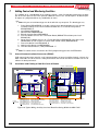
Installation and Cabling of Add On Cards & Boards
CAB1911 TO MAINS EARTH
BUS 3
CN1
CAB2200
POWER
CN1
CN10
A BATT BOX IS REQ
IF THESE BRDS ARE FITTED
CN4
CN3
CN1
CN9
+27V
CN2
BUS 1
0V
BUS 2
CN5
CN8
OPTIONAL BOARDS
AGENT TERMINATION
RELAY
FAN TERMINATION
INPUT
SOUNDER TERMINATION
CAB1905
MAIN CONTROL CARD
OTIONAL
BRIGADE BOARD
CN2
CAB2200
PSU1887
CN2
0V
+2 7V
CN6
+2 7 V
CN 3
CN 4
0V
TB1-T B5
POW ER
CN1
CN 2
CN2 CN1
CN1
N/0
C OM N/C
A LA RM 1
N /0
CO M N/C
FAUL T
N/0
COM N/C
IS OL ATE
N /0
CO M
BATT FA L
I
N/C
N/0
COM
AL ARM 2
N/C
CN2 CN1
OPTIONAL CARDS
AGENT RELEASE
FAN CONTROL
GENERAL INDICATOR
CN1
CAB2200
CN2
POW ER
CN4
CN3
CAB2200
OPTIONAL BOARDS
AGENT TERMINATION
RELAY
FAN TERMINATION
INPUT
SOUNDER TERMINATION
A BATT BOX IS REQ
IF THESE BRDS ARE FITTED
CN1
CN2
POW ER
OPTIONAL CARDS
AGENT RELEASE
FAN CONTROL
GENERAL INDICATOR
0V +27V
C N2
0V +27V
7.2
CN3 CN4
OPTIONAL BOARDS
AGENT TERMINATION
RELAY
FAN TERMINATION
INPUT
SOUNDER TERMINATION
A BATT BOX IS REQ
IF THESE BRDS ARE FITTED
CAB2117
CAB1905
CAB1902
BOARD
IDENTIFIERS:
BRD25ARB PCB0783
BRD25ATB PCB0787
BRD25BBA PCB0779
BRD25EWRB PCB0770
BRD25FCB PCB0783
BRD25FTB PCB0780
+27v Power fitted when Relay or Termination Boards are fitted
(AGENT RELEASE MODULE)
(AGENT TERMINATION BOARD)
(BRIGADE BOARD)
(8 WAY RELAY BOARD)
(FIRE FAN MODULE )
(FAN TERMINATION BOARD)
BRD25GIB PCB0781
BRD25MCB PCB0769
BRD25PSU PCB0813
BRD25SIPB PCB0778
BRD25SOPB PCB0772
(GENERAL INDICATOR CARD)
(MAIN CONTROL CARD)
(POWER SUPPLY UNIT)
(SINGLE INPUT BOARD)
(SOUNDER OUTPUT BOARD)
CAB1925 to Batteries
Figure 18: Typical Wiring, Ancillary Card and Board Positioning Within the ABS FACP
Page 18
ZONESENSE PLUS INSTALLATION, COMMISSIONING & OPERATION
7.3
Terminating the Communications Bus
+
-
RS485
Front Panel
Card 1
CN9
Front Panel
Card 2
BUS 1 ( B1 )
Note: If Backpan boards AND remote facilities
are fitted the front panel cards are not terminated
K1
Backpan
BRD 1
CN5
Fit K1 if only the
Main Control
Card is used as
the FACP or
1 Bus is used.
SEE TABLE
BELOW
INSERT ( Link 1 in Table below )
LK1
Backpan
BRD 2
BUS 2 ( B2 )
INSERT
LK1 ( Link 2 in Table below )
Fit LK1 to last LCS
BUS 4 ( B 4)
To
TB1 Agent Termination Board
TB2
LCS 1
INSERT
LK1
LCS 2
If Agent Release is fitted to the FACP there will be an Agent Termination Board mounted on the Backpan.
Local Control Stations can then be fitted at some location remote from the FACP. These LCS's communicate
with the ATB via a second RS485 bus hence the last LCS in the chain will have to be terminated
Remote
Card 1
Remote
Card 2
INSERT
( Link 3 in Table below )
LK1
BUS 3 ( B 3)
Shield
Figure 19: RS485 Communication Bus Terminating
Linking Table
Link
1
2
3
Bus Configuration
B1
B1,2
X & K1
X
X
B1,3
X
X
B1,2,3
B,2
B2,3
B3
X
X
X & K1
X
X
X & K1
X = Insert Link
B1: Bus 1 to Front Panel Cards
B2: Bus 2 to Backpan Boards
B3: Bus 3 to Remote facilities
B4: Bus 4 Local Control Station cabled to the backpan Agent Release Board.
Page 19
ZONESENSE PLUS INSTALLATION, COMMISSIONING & OPERATION
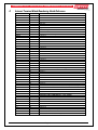
8
Internal Terminal Block Numbering Quick Reference
Terminal Block
TP Number
TB2/1
2
3
28
29
TB3/1
2
3
4
25
26
27
TB13/1
2
3
4
5
6
7
8
TB14/1
2
3
4
5
6
7
8
1
2
3
4
5
6
7
8
9
10
11
12
13
14
15
16
TB4/1
2
3
4
5
6
7
8
17
18
19
20
21
22
23
24
TB5/1
2
3
4
25
26
27
28
5
6
7
8
9
10
TB12/1
2
3
29
30
31
32
33
34
35
36
37
EN54
COMMUNICATIONS EXTERNAL
RS485 +
RS485 Shield
INPUTS
Common
Spare
Class Change
Alert
ZONES ( 24mA / Zone )
+ Zone 1
- Zone 1
+ Zone 2
- Zone 2
+ Zone 3
- Zone 3
+ Zone 4
- Zone 4
+ Zone 5
- Zone 5
+ Zone 6
- Zone 6
+ Zone 7
- Zone 7
+ Zone 8
- Zone 8
MONITORED OUTPUTS ( 500mA / O/p )
Alarm 1 +
Alarm 1 Alarm 2 +
Alarm 2 Alarm 3 +
Alarm 3 Alarm 4 +
Alarm 4 MODIFIED OPEN COLLECTOR OUTPUTS ( 25 mA /O/P )
Fire +
Fire Fault +
Fault OUTPUTS VOLT FREE RELAY ( 1A @ 30VDC )
NO Alarm
C Alarm
NC Alarm
NO Fault
C Fault
NC Fault
Aux 24VDC + (Mon 500mA)
Aux 24VDC –
Reset 3sec 24VDC 100mA max pulse
Page 20
ZONESENSE PLUS INSTALLATION, COMMISSIONING & OPERATION
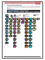
9
Status and Programming Screens
The following shows all the screens that are possible in the FACP and how to navigate through
them. I f a screen is not available it means that option has not been installed or is not available to the
model in use.
Operating Main Menu
LEVEL 1
STATUS
9.1
LEVEL 2
TEST
FAULTS
DISABLE
LEVEL 3
SYSTEM
PROGRAMMING
Level 1 to 3 Status Screens
PRESS E NTER
PRESS THE SE KEYS
TO S ET YE S / NO, OFF / ON,
OFF NORMAL
PRE SS: MOVE FORWARD
OR BACKWARD
THROUGH T HE MENU
PRES S MOVE FORWARD
THROUGH THE ME NU
LEGEND:
MENU
ENTER
STATUS
M ENU
ENTER
CANCEL
ME NU
ENT ER
OUTP UT S
MENU
ENTER
BRIGADE
MENU
ENTER
RELAYS
M ENU
ENTER
FIRE FAN
M ENU
ENTER
ALARM 1
OFF /NORM
ALARM 1
OFF / ON
RELAY 1
OFF / ON
FAN 1
OFF / ON
ALARM 2
OFF/NORM
FAULT
OFF / ON
RELAY 2
OFF / ON
ALARM 3
OFF/NORM
DISABLE
OFF / ON
ALARM 4
OFF/NORM
FIRE
OFF/NORM
S OUNDE RS
AGENT
M ENU
ENTER
M ENU
ENTER
CANCEL
INP UT
PRESS CANCEL AT
ANY TIME TO BACK
OUT OF THE MENU
VOLTAGE
MENU
ENTER
M ENU
ENTER
SNDR 1
OF F/NORM
INPUT 1
OFF / ON
BATT V
26.8V
FAN 2
OFF / ON
S NDR 2
OFF/NORM
INP UT 2
OFF / ON
CHRGR V
27.0V
RELAY 3
OFF / ON
FAN 3
OFF / ON
S NDR 3
OFF/NORM
INP UT 3
OFF / ON
SY STE M V
27.0V
BATT FAIL
OFF / ON
RELAY 4
OFF / ON
FAN 4
OFF / ON
SNDR 4
OF F/NORM
INP UT 4
OFF / ON
ALARM 2
OFF / ON
RELAY 5
OFF / ON
SNDR 5
OF F/NORM
INP UT 5
OFF / ON
FAULT
OFF/NORM
RELAY 6
OFF / ON
SNDR 6
OFF /NORM
INPUT 6
OFF / ON
ANC OUT
OFF/NORM
RELAY 7
OFF / ON
S NDR 7
OFF /NORM
INPUT 7
OFF / ON
RELAY 8
OFF / ON
SNDR 8
OFF/NORM
INPUT 8
OFF / ON
AGENT
OFF /NORM
Page 21
SOF TWARE
VER E1.2
ZONESENSE PLUS INSTALLATION, COMMISSIONING & OPERATION
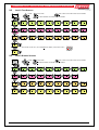
9.2
Level 2 Test Screens
MENU
ENTER
LEGEND:
TE S T
PRESS E NTER
CANCEL
PRESS CANCEL AT ANY TIME TO BACK OUT OF THE MENU
MENU
ENTER
PRESS MOVE FORWARD / BACKWARD THROUGH THE MENU
M ENU
ENT ER
CANCEL
ALARM
TE S T
MENU
ENTER
Z ONE 1
T ES T
FAULT
TE S T
M ENU
ENTER
Z ONE 1
T ES T
WALK
TE ST
M ENU
ENTER
ZONE 1
TE S T
LAMP
TE S T
M ENU
ENTER
ZONE 2
TE ST
ZONE 3
TE S T
ZONE 4
TE ST
ZONE 5
TE ST
ZONE 6
TE ST
ZONE 2
TE S T
ZONE 3
TE ST
ZONE 4
TE ST
ZONE 5
TE ST
ZONE 6
TE ST
ZONE 2
TE S T
ZONE 3
TE ST
ZONE 4
T ES T
ZONE 6
TE S T
ZONE 5
T ES T
PRESS ENTE R TO START TEST ( TEST PERFORMED FOR TIMEOUT ) PRESS RESET TO HALT
BATTERY
T ES T
9.3
ZONE 7
T ES T
ZONE 8
T ES T
ZONE 7
T ES T
ZONE 8
T ES T
Z ONE 7
T ES T
ZONE 8
TE S T
RESET
M ENU
ENTER
Level 2 Disable Screens
DISABLES
M ENU
ENTER
LEGEND:
ME NU
ENT ER
CANCEL
PRESS ENTER
PRESS CANCEL AT ANY TIME TO BACK OUT OF THE MENU
P RESS MOVE FORWARD / BACKWARD THROUGH THE MENU
CANCEL
MENU
ENTER
Z ONES
ME NU
0 DISABLED ENT ER
ZONE 1
ACTIVE
ZONE 2
ACTIVE
Z ONE 3
ACTIV E
Z ONE 4
ACTIV E
ZONE 5
ACTIVE
Z ONE 6
ACTIVE
M ENU
OUTP UTS
0 DISABLED ENTER
ALARM 1
ACTIVE
ALARM 2
ACTIVE
ALARM 3
ACTIVE
ALARM 4
ACTIVE
ANC OUT
ACTIVE
FIRE
ACTIV E
FAULT
ACTIVE
RELAYS
MENU
0 DISABLED ENT ER
RELAY 1
ACTIVE
RELAY 2
ACTIV E
RELAY 3
ACTIVE
RELAY 4
ACTIVE
RELAY 5
ACTIVE
RELAY 6
ACTIVE
RELAY 7
ACTIVE
RELAY 8
ACTIVE
S OUNDE RS M ENU
0 DISABLED ENTER
S NDR 1
ACTIVE
SNDR 2
ACTIVE
S NDR 3
ACTIVE
SNDR 4
ACTIVE
SNDR 5
ACTIVE
SNDR 6
ACTIVE
SNDR 7
ACTIVE
SNDR 8
ACTIVE
Page 22
ZONE 7
ACTIVE
ZONE 8
ACTIVE
ZONESENSE PLUS INSTALLATION, COMMISSIONING & OPERATION
9.4
Level 3 System Programming
PASSWORD MENU
ENTER
SYSTEM
MENU
ENTER
BUZZER
M ENU
ENTER
CANCEL
EARTH MON
YES / NO
LEGEND:
MENU
ENTER
PRESS ENTER
PRESS: MOVE FORWARD
OR BACKWARD
T HROUGH THE MENU
BRIGADE
YES / NO
PRESS THESE KEYS
TO SET YES / NO
PRESS MOVE FORWARD
T HROUGH THE MENU
CANCEL
PRESS CANCEL AT
ANY TIME TO BACK
OUT OF THE MENU
RELAYS
YES/ NO
FIRE FAN
YES / NO
AGENT
YES / NO
SOUNDERS
YES / NO
INDICATE
YES / NO
SW I NDIC
YES / NO
INPUTS
YES / NO
LAM
YES / NO
C OD E
EN54
Page 23
MENU
ENTER
R ES OU ND
YES / NO
ALARM
YES / NO
ZONESENSE PLUS INSTALLATION, COMMISSIONING & OPERATION
9.5
Level 3 Programming Menu
PROGRAM
MENU
ENTER
ZON ES
MENU
ENT ER
SELECT
ZONE 1 - 8
NORMAL
NON LATCH
AVF
AGENT T2
AGENT T1
DOUBLE
KNOCK
1 TO 8
LEGEND:
ZO N E
DELAY
M ENU
ENTE R
SELECT
ZONE 1-8
8
SELECT
DELAY
ACF
ISOALTE PRESS ACF TO ISOLATE CIRCUITS EXTERNAL TO FACP
M ENU
ENT ER
ASSIGN MCP
1 TO A ZONE
ACF
ISOALTE
CLOCK
M ENU
ENTE R
SELECT
D AY
TIM E
CHANG E
DAY TIME
MENU
ENT ER
O N MENU
MENU
ENTER
OF F
1 TO 8
RELAYS
MENU
ENT ER
SELECT
RELAY
1 TO 8
MENU
ENT ER
ENT ER
ENT ER
FIRE FAN
INHIBIT
ZN 1 TO 8
MENU
ENT ER UPDATE MENU
SET
ZONE #
12345678
MENU
ENT ER
MENU
ENTER
SELECT
STYLE #X
1
DISPLAY
########
MENU
ENTER
Z LABELS
MENU
ENTER
EO L
10uf
MENU
ENTER
EO L
RES 3K3
Z ON E
S /C
M ENU
ENT ER
ZO N E
ALARM
SELECT
BGD ALM 2
ZN 1 TO 8
FI RE OUT
EVAC Y/N
R# SWI TCH
1 TO 8
3 ME NU
4 ENTER
5
ME NU
ENTER
RELEASE
PYR OGEN
PRESS S/W
N/O
RELEASE
SOLENOI D
PRESS SW
N/ C
RELEASE
M ET RO N
PRESS SW
NONE
ME NU
ENTER
SET STYLE FROM
1 TO MAX
AVAILABLE
IN MODULE
N: NO
RE SET
BACKOUT OF MENU
ME NU
ENTER
YES
NO
FUNCTION
3,4,5 WIRE
MAX
INDICATE
STYLE
R# I/P
1 TO 8
CANCEL
O FF
MENU
ENTER
SE T
SNDR #
12345678
R# Z-ISOL
1 TO 8
UPDATE MENU
ALARM
ZN 1 TO 8
MENU
ENT ER
ON
M ENU
SOUN DERS ENTE
R
R# Z-FLT
1 TO 8
OFF
1 TO 4
AG ENT
SELECT
BGD ALM 1
ZN 1 TO 8
Y: YES
R# Z-ALRM
1 TO 8
1 TO 8
SELECT
FAN
1,2,3,4
ANC OUT
ZN 1 TO 8
ALARM 4
ZN 1 TO 8
ALARM 3
ZN 1 TO 8
UPDATE MENU
EXAMPLE OF ACTIVATING ZONE TO TURN ON/OFF SELECTED OUTPUT
O N M ENU
MENU
ENT ER
PRESS ENTER TO GO TO SUB MENU, SET MENU OR UPDATE PROGRAM
PRESS M OVE FORWARD THROUGH THE MENU
ALARM 2
ZN 1 TO 8
ALARM 1
ZN 1 TO 8
PRESS CANCEL AT ANY TIME TO BACK OUT OF THE MENU
PRESS MOVE FORWARD / BACKWARD THROUGH THE MENU
M O VE
T HRO UGH
DAY TIME
OU TPUTS
CANCEL
CANCEL
ME NU
ENTER
RELEASE MENU
CONSTANT ENT ER
EXAMPLE OF SELECTING FUNCTION WIRE TO BE USED
AUTO DELAY
SET 0 - 60S
MAN DELAY
SET 0 - 60
LCS
1
SET
0 - 60 SEC
S ET
0 - 60 SEC
SE T
1 TO 4
NOTE:
THESE MENUS ARE ONLY AVAILABLE
IF RELAYS, FIRE FAN, AGENT
SOUNDERS HAVE BEEN CHANGED
TO YES IN THE SYSTEM MENU
EDI T
TE XT
SELECT
ZO NE
MENU
ENT ER
EDI T
TE XT
EO L
RES4K7
TO EDIT DISPLAY
TEXT USE
EOL
RES 6K8
TO MOVE THROUGH THE
ALPHABET / NUMBERS
EOL
RES 10K
Z ON E
FAULT
Page 24
TO MOVE THROUGH
THE WORD
ZONESENSE PLUS INSTALLATION, COMMISSIONING & OPERATION
10
List of Compatible Devices
The following range of devices have been approved to be used with the ZoneSense PLUS.
Apollo
Series 60, grade 1 heat (60deg Celsius)
Series 60, grade 2 heat (65deg Celsius)
Series 60, grade 3 heat (75deg Celsius)
Series 60, range 1 heat (80deg Celsius)
Series 60, range 2 heat (100deg Celsius)
Series 60, Type A Heat
Series 60, Type B Heat
Series 60, Type C Heat
Series 60, Type D Heat
Series 60, Ionisation Smoke
Series 60, integrating Ionisation Smoke
Series 60, Photoelectric Smoke
Base (for above detectors )
Series 60, Duct Sampling Unit
Order Code
55000-100AMP
55000-101AMP
55000-102AMP
55000-103AMP
55000-104AMP
201-0023
201-0024
201-0025
201-0026
201-0027
55000-210AMP
201-0028
201-0029
214-0001
AMPAC
FIRERAY 2000 Beam Detector
ACP-01 Manual Call Point Red
ACP-01 Manual Call Point Yellow
ACP-01 Manual Call Point White
ACP-01 Manual Call Point Green
FP/2 Manual Call Point Red
FP/2 Manual Call Point White
220-0004
213-0017
213-0018
213-0019
213-0020
213-0021
213-0022
Hochiki
DCA-B-6OR MKV Heat Detector Type A
DCC-A Type A Heat
DCD-A Type A Heat
DFE-60B Type B Heat
DFJ-60B Type B Heat
DCA-B-90R MK 1 Heat Detector Type C
DCC-C Type C Heat
DCD-C Type C Heat
DFE-90D Heat Detector Type D
DFJ-90D Type D Heat
SIH-AM Ionisation Smoke Detector ( High )
SIH-AMB Ionisation Smoke Detector ( Normal )
SIJ-AS Ionisation Smoke Detector
SIJ-ASN Ionisation Smoke Detector
SLK-A Photoelectric Smoke Detector
SLR-AS Photoelectric Smoke Detector
YBF-RL/4AH4M Base for the above detectors
YBN-R/4A base
YBO-R4A base
A100 Duct Probe with SLR-AS Photoelectric Smoke
HF-24A MK 1 Ultra-Violet Flame Detector
DH-98AS Duct Probe with SLR-AS Photoelectric Smoke
202-0050
202-0008
202-0039
202-0009
202-0340
202-0037
202-0010
202-0341
202-0011
202-0342
202-0012
202-0025
202-0344
202-0345
202-0013
202-0046
202-0014
202-0349
202-0351
202-0347
202-0038
202-0348
Page 25
ZONESENSE PLUS INSTALLATION, COMMISSIONING & OPERATION
10.1
Item Numbers
2580-1100
4 Zone ABS (BX1)
2580-1200
8 Zone ABS (BX1)
2580-0100
4 Zone Metal (BX10)
2580-0200
8 Zone Metal (BX10)
2510-9001
Ancillary Cabinet ABS (BX1)
Add-On Panel
4310-0040
Input Board (Fit max of 1)
4310-0050
Relay Board (panel) (Fit max of 1)
4310-0060
Sounder Board (Fit max of 1)
4310-0070
Brigade Interface Board (Fit max of 1)
Add-On External
4310-0037
LED Annunciator Mimic (LAM)
4310-0055
Relay Board (remote) (Fit max of 1)
Accessories
ENC1851-A
Joiner for ABS multiple cabinets
ENC3016-A
Flush mount surround for metal (BX10) cabinet
Page 26
ZONESENSE PLUS INSTALLATION, COMMISSIONING & OPERATION
11
Glossary of Terms
ACF:
ACKD:
AH:
AHU:
ALM:
ASE:
AVF:
AZF:
AZC:
COM:
CIC:
CN:
C/O:
CPU:
DGP:
EARTH:
EOL:
FACP:
FDS:
FFF:
FLT:
FP:
GND:
Ia:
Ida:
Idd:
Iq:
I/O:
LCD:
LCS:
LED:
MAF:
MCP:
MOV:
NIC:
N/C:
N/O:
PCB:
P/S:
PSM:
REM:
SPOT:
TB:
VDC:
ANCILLARY CONTROL FACILITY
ACKNOWLEDGED
AMP HOUR
AIR HANDLING UNIT
ALARM
ALARM SIGNALLING EQUIPMENT
ALARM VERIFICATION FACILITY
ALARM ZONE FACILITY
ALARM ZONE CIRCUIT
RELAY COMMON CONTACT (WIPER)
CONTROLLER INTERFACE CARD
CONNECTOR
CHANGE OVER CONTACTS
COMMON PROCESSOR UNIT
DATA GATHERING POINT
BUILDING EARTH
END OF LINE
FIRE ALARM CONTROL PANEL
FIRE DETECTION SYSTEM
FIREFIGHTER FACILITY FORMAT
FAULT
FRONT PANEL
GROUND (0 VOLTS) NOT EARTH
CURRENT DRAW IN ALARM
CURRENT DRAW IN ALARM WITH DEVICES ACTIVATED
CURRENT DRAW IN ALARM WITH DEVICES DEACTIVATED
QUIESCENT CURRENT
INPUT/OUTPUT
LIQUID CRYSTAL DISPLAY
LOCAL CONTROL STATION
IGHT EMITTING DIODE
ASTER ALARM FACILITY
ANUAL CALL POINT
ETAL OXIDE VARISTOR (TRANSIENT PROTECTION)
ETWORK INTERFACE CARD
ORMALLY CLOSED RELAY CONTACTS
ORMALLY OPEN RELAY CONTACTS
RINTED CIRCUIT BOARDS
OWER SUPPLY
OWER SUPPLY MODULE
EMOTE
INGLE PERSON OPERATING TEST
ERMINAL BLOCK
OLTS DIRECT CURRENT
Page 27
ZONESENSE PLUS INSTALLATION, COMMISSIONING & OPERATION
12
Definitions
Addressable system - a fire alarm and detection system that contains addressable alarm zone
facilities or addressable control devices.
Alarm Signalling Equipment (ASE) – circuitry that provides the necessary indication to the
monitoring service providers.
Alarm Verification Facility (AVF) - that part of the FACP, which provides an automatic resetting
function for spurious alarm signals so that they will not initiate Master Alarm Facility (MAF), or ACF
functions inadvertently. Programming sets this option
Alarm Zone - the specific portion of a building or complex identified by a particular alarm zone
facility.
Alarm Zone Circuit (AZC) - the link or path that carries signals from an actuating device(s) to an
alarm zone facility(s).
Alarm Zone Facility (AZF) - that part of the control and indicating equipment that registers and
indicates signals (alarm and fault) received from its alarm zone circuit. It also transmits appropriate
signals to other control and indicating facilities.
Alert Signal - an audible signal, or combination of audible and visible signals, from the emergency
warning system to alert wardens and other nominated personnel as necessary to commence
prescribed actions.
Ancillary Control Facility (ACF) - that portion of the control and indicating equipment that on
receipt of a signal initiates predetermined actions in external ancillary devices.
Ancillary Equipment - remote equipment connected to FACP.
Ancillary Relay - relay within FACP to operate ancillary equipment.
Ancillary Output - output for driving ancillary equipment.
Conventional System - is a fire detection system using a dedicated circuit for each alarm zone.
Distributed System - a fire alarm and detection system where sections of the control and indicating
equipment are remotely located from the fire indicator panel or where sub-indicator panel(s)
communicate with a main fire indicator panel.
Field Connections - are connections made to FACP or ancillary equipment at the project during
installation.
Fire Alarm System - an arrangement of components and apparatus for giving an audible, visible, or
other perceptible alarm of fire, and which may also initiate other action.
Fire Detection System - an arrangement of detectors and control and indicating equipment
employed for automatically detecting fire and initiating other action as arranged.
Fire Alarm Control Panel (FACP) - a panel on which is mounted an indicator or indicators together
with associated equipment for the fire alarm or sprinkler system.
Fire Resisting - an element of construction, component or structure which, by requirement of the
Regulatory Authority, has a specified fire resistance.
Indicating Equipment - the part of a fire detection and or alarm system, which provides indication of
any warning signals (alarm and fault), received by the control equipment.
Interface - The interconnection between equipment that permits the transfer of data.
Master Alarm Facility (MAF) - that part of the control and indicating equipment which receives
alarm and fault signals from any alarm zone facility and initiates the common signal (alarm and/or
fault) for transmission to the fire control station where appropriate. Bells and other ancillary functions
may be initiated from this facility.
Power Supply - that portion of the FACP which supplies all voltages necessary for its operation.
Page 28
ZONESENSE PLUS INSTALLATION, COMMISSIONING & OPERATION
13
Battery Capacity Calculation
INTRODUCTION
The standby power source capacity, or battery capacity, determines how long the system will
continue to operate in the event of the loss of the primary power source. It therefore becomes
necessary to calculate the battery and hence power supply / battery charger capacity required for
each installation.
The following calculator has been designed to determine the required capacity to meet the required
standard. Should an existing panel be expanded the required battery and power supply capacity
should be recalculated to ensure the panel continues to operate within the standard.
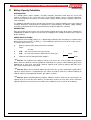
DESCRIPTION
Enter the number of units listed in the left hand column which go to make up the panel, complete the
multiplication to obtain the quiescent current then multiply by the standby and alarm hours required
by the standard.
POWER SUPPLY RATING
The minimum Power Supply Rating ( 4 ) is obtained by calculating the manufacturers recommended
battery charge current and [ see Note ] ( 1 ) then adding the quiescent current of the entire system (
2 ) and the alarm current ( 3 ).
1.
2.
Battery Capacity (AH) (determined from Calculator)
Amps
24 x 0.8
Add
Quiescent Current of the System (Iq)
3.
Add
4.
Minimum Current Rating of Power Supply is
=
=
the extra current that is drawn when in alarm (Ia) =
Amps
Amps
=
Amps
Note #1: The capacity of the battery shall be such that in the event of failure of the primary
power source the batteries shall be capable of maintaining the system in normal working (quiescent)
condition for at least 24 h, after which sufficient capacity shall remain to operate two worst case
AZF’s and associated ACF’s for 30 min.
Note #2: Where the fire control station will not receive the system's total power supply failure
signal or, Agent Release is incorporated in the FACP, the battery shall have sufficient capacity to
maintain normal system operation for 96 h. plus 30min. in alarm.
Note #3: When calculating battery capacity, allowance shall be made for the expected loss of
capacity over the useful life of the battery. A new battery shall be at least 125% of the calculated
capacity requirements, based on a loss of 20% of its capacity over the useful life of the battery.
Page 29
ZONESENSE PLUS INSTALLATION, COMMISSIONING & OPERATION
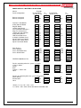
POWER SUPPLY & BATTERY CALCULATOR
Criteria
Panel Configuration
Example
Iq Calculation
No Off X mA
Iq
= Iq
Iq Calculation
No Off X mA
Iq
= Iq
Basic 4 zone panel
Basic 8 zone panel
40.5
1
40.5
40.5
Interface Cards/Boards
8 Way Sounder Board
Brigade Board
16 Way Input Board
Fan Termination Board & 4
Way Fan Control Card
16 Way General Indicator
8 Way Relay Board
LED Annunciator Card
8 Switch & Indicator Card
Agent Front Panel Control
Agent Local Control Panel
Agent Termination Board
5.5
21.4
5.3
6.5
6
3.4
4.7
11.5
3.4
14.6
5.8
37
1
1
1
1
1
1
1
1
5.5
2
5.3
12.5
6
3
4.7
11.5
5.5
21.4
5.3
6.5
6
3.4
4.7
11.5
0
0
0
0
0
0
64.3
Zone Devices
Series 60 Heat
Series 60 Photoelectric
Series 60 Ionisation
0.057
0.038
0.043
21
32
12
0.057
0.038
0.043
1.2
1.2
0.5
Iq =
107.9
50
20
80
=
Ida=
50
200
320
150
0
720
20
100
40
400
Idd=
440
FIRERAY 2000 Beam Det.
13
Iq =
Devices activating when the system is in alarm
1 Zone in Alarm
50
Relays
20
Bells
80
Outputs = Total in mA
Other
Ida=
Devices de-activating when the system goes into alarm
Aircon Relays
20
Electric locks
100
Other
Idd=
I Alarm ( Ia = Iq + Ida – Idd ) = mA
Ia = 107.9 + 720 – 440 = 387.9 rounded for calculation 390
Page 30
1
10
4
2
4
ZONESENSE PLUS INSTALLATION, COMMISSIONING & OPERATION
Criteria
Battery capacity at end of
battery life
=
=
Note: ☞1,000ma = 1 Amp
New battery capacity
requirement
Example
( Iq x 24 ) + ( Ia x 0.5 )
Note: the figure of 24
above should be 96 if
Agent Release is used.
=
=
Ah
=
=
( Iq x 24 ) + ( Ia x 0.5 )
( rounded )
( 100mA x 24 ) + ( 390mA x 0.5 )
=
=
2400mA + 195mA = 2595
2.595 Ah
=
Ah x 1.25
=
2.595 x 1.25
=
Ah
=
3.24 Ah
Rounded up to nearest
available
Ah
3.2 Ah
=
PRIMARY POWER SOURCE CALCULATIONS
=
Battery Charger Current
Requirement: Battery is charged for 24 hrs. to provide 5Iq + 0.5Ia
=
Ah Requirement
=
=
=
Battery Charging Current
Required
=
e is the battery efficiency,
0.8
=
( 5x Iq ) + ( 0.5 x Ia )
Ah
Ah above
24 x e
A
=
( 5x Iq ) + ( 0.5 x Ia )
=
=
=
( 5 x 100 ) + ( 0.5 x 390 )
500 + 195
0.695Ah
=
0.695
24 x e
.0363A
=
Power Supply
Requirement
Select the greater, 1 or 2
1. Ia + non- battery backed ancillary alarm loads
2. Iq + non – battery backed quiescent loads
If the power supply is used as the charger the current rating of the supply shall be [(1 or 2) + battery
charger current].
Note: Remember to take into account ALL outputs that will be switched on when calculating
Ida.
Page 31
ZONESENSE PLUS INSTALLATION, COMMISSIONING & OPERATION
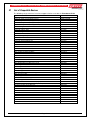
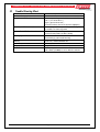
14
Trouble Shooting Chart
Problem
No Mains Power
Supply fault LED illuminated
Earth Fault LED illuminated
System Fault LED illuminated
Warning System Fault LED illuminated
RS485 Communication Loop not
working
Can not access a menu
Forgotten Password
Alarm Fault
Solution
Check mains Fuse
Check output voltage it should be set to 27.2V.
Low = (less than 26.5V )
High = (greater than 28V )
Check the battery has been connected properly
Check all input and output cabling and wiring
assemblies for short to ground
Ensure correct panel configuration
Check all connections for loose wiring
Check correct E.O.L is fitted
Check wiring is connected correctly
Refer to LCD. This may identify where there is a
break in the communication line
Incorrect Password entered
Ring AMPAC
Make sure you have a 10K Ohm EOL resistor fitted
and a diode (1N4004) in series with the sounder
Page 32
ZONESENSE PLUS INSTALLATION, COMMISSIONING & OPERATION
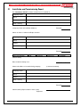
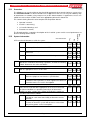
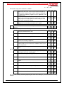
15
Installation and Commissioning Report
This ZoneSense PLUS Fire Alarm Control Panel is installed at:
Company Name
Street
Suburb
State / Country
Postcode
(Company Name & Installation Address)
Owner or Owners' Authorised Representative:
Company Name
Street
Suburb
State / Country
Postcode
Type of Installation:
NEW
MODIFIED
ADDITION
UPGRADE
(Please Circle)
Date of commissioning tests:
/
Name and address of commissioning company,
(in 'BLOCK LETTERS')
Company Name
Street
Suburb
State / Country
Postcode
Commissioning Representative: Name (Print)
Signature:
Page 33
/
ZONESENSE PLUS INSTALLATION, COMMISSIONING & OPERATION
15.1
Procedure
The following tests are the minimum that should be performed when commissioning a system using
the ZoneSense PLUS Fire Alarm Control Panel. Supplements to these tests may be added by way
of attachments or notation (using waterproof ink) to this documentation. If supplements or tests are
added reference to them shall be made at an appropriate point on this document.
This Commissioning Record is to be completed in conjunction with the:
Operator’s manual;
Installer’s statement(s);
'as-installed' drawings; and
Detector test records,
15.2
System Information
Are listed in the operator's manual;
ii
Are compatible with the installed AZF,
iii
Do not exceed the permitted number of detectors on each
circuit; and
iv
Are installed in an environment for which they are suitable.
No
i
Yes
Tick relevant box
1. Ensure that all detectors used in the system -
Not
Applicable
The Record provides a complete description of the installed system and its tested performance at
the time of being commissioned.
2.
Check that the primary power source for the system has been
provided in accordance with wiring regulations, and that the isolating
switch disconnects the active conductors.
3.
Check that the detector and the FACP locations are in accordance
with the appropriate clauses of the code.
4. Alarm zone circuit:
5.
i
Measure each alarm zone circuit voltage, and ensure each is
within the equipment manufacturer's specifications.
ii
Insulation resistance of all installation wiring measured in
accordance with regulations or similar approved method and
record the worst case result in the logbook.
Open circuit and short circuit the end of line device on each alarm
zone circuit, or conduct other appropriate tests to ensure that fault
and alarm conditions are operating correctly on all alarm zone
facilities on other sections of the control and indicating equipment.
6. FACP test to be carried out as follows:
i
ii
Operate each alarm test, fault test, isolate and reset facility
provided for each alarm zone facility to determine correct
operation.
Operate the primary power source switch on and off at least
five times to check the system will not cause a false alarm
from primary power source interruptions.
Page 34
ZONESENSE PLUS INSTALLATION, COMMISSIONING & OPERATION
es
Y
No N/A
7. Detector testing to be carried out as follows:
i
Test each installed detector or sampling point with an
approved in-situ tester, and ensure that each detector has
operated in the correct range, and the alarm has indicated on
the control and indicating equipment and, if applicable, at the
detector tested.
Confirm that response of the system does not exceed 6 s
from the time the detector operates until the master alarm
facility registers the alarm (while in normal mode) on each
zone, or 32 s when AVF is fitted.
Record tests on detector test record as required by the
appropriate local authority and attach to the report.
Check the operation of each manual call point and all other actuating
devices.
ii
iii
8.
9. For Flame detectors perform the following
i
Check that the number and type of detectors provide
adequate protection of the area.
ii
Check that there are no 'blind' spots in areas protected.
iii
Check that detectors are rigidly fixed.
iv
Check that detectors are properly connected to compatible
control and indicating equipment.
v
Check that detector lenses are clean and adequately
protected from dust and extraneous radiation sources where
these are present.
Test the detection response to a flame source or simulated
flame.
vi
10. For Smoke detection sampling systems, perform the following
i
Measure the response time of all sampling points using
smoke placed at each sampling point.
ii
Check the back-up power supply capacity.
iii
Check the operation of alarm settings and indicators.
iv
Check operation of remote indication of alarm and fault
signals.
v
Check the operation of airflow failure indicators.
vi
Check the operation of the system (signal) failure indicators.
vii
Check the isolate/reset functions.
viii
Check the fault and alarm test facilities.
11. Test each ancillary function by operating the alarm zone facility(ies), associated with the ancillary
function.
Page 35
ZONESENSE PLUS INSTALLATION, COMMISSIONING & OPERATION
es
Y
No N/A
12. Alarm Signalling
i
Check that the master alarm facility is able to receive the
alarm signal by operating each alarm zone facility.
ii
Check that the master alarm facility initiates an alarm to the
fire control station equipment.
13. Battery Supply
i
Check that both the primary and secondary power sources
are of a suitable type and capacity.
ii
Perform a float voltage check according to the battery
manufacturer's recommendation to ensure that the charger
type and setting is correct.
Type of battery.
Charger type.
Float voltage/ required.
Charger set at.
14.
Check that all alarm zone facilities have been correctly labelled and
that the alarm zone is immediately apparent from the labelling.
15.
Check the 'as-installed' drawings are marked up, are consistent with
the installation and the operator's manual is relevant to the
installation.
16.
Ensure the results of these tests are recorded in the system logbook.
Page 36
ZONESENSE PLUS INSTALLATION, COMMISSIONING & OPERATION
16
Statement of Compliance
Please PRINT
Name of building
Address
Fire Alarm Control Panel Brand Name
I/WE have installed in the above building
an alteration to the system manufactured by,
OR
a system manufactured by
Name of Service Provider
The system is connected to
Monitoring service provider by a permanent
, non-permanent connection (
Date of connection
tick)
/
/
No
Ancillary equipment installed / connected to the control and indicating equipment.
(see Commissioning Of Cards and Boards)
Yes
Current drain of ancillary loads powered from the FACP power supply
Primary power source voltage
Battery type and capacity
Manufacturer
AH
Is maintenance agreement held for the system?
Yes
Operator's handbook supplied?
Yes
Logbook supplied?
Yes
'As-installed' drawings supplied?
Yes
Portions of the building not protected by this system are; (Please PRINT )
1.
3.
5.
7.
9.
2.
4.
6.
8.
10.
I/We
1.
2.
3.
Print Name/s
Page 37
No
No
No
No
ZONESENSE PLUS INSTALLATION, COMMISSIONING & OPERATION
hereby certify that the installation has been thoroughly tested from each
actuating device and that a test of the transmission of the alarm signal to the monitoring service
provider has been satisfactorily carried out.
I/We further certify that the whole system and all components in connection therewith are installed
entirely in accordance with the current appropriate local requirements.
except with regard to the following details which have already been approved", approval
attached.
Strike out the bolded sentence if there have not been any exceptions.
Signature
Date
Installing Company
Please PRINT or Stamp
Page 38
/
/
ZONESENSE PLUS INSTALLATION, COMMISSIONING & OPERATION
17
Installation Details
#
Alarm
Zone
#
Indicate with a number in brackets the number of actuating devices in concealed spaces.
Number and Type of Actuating Devices
Number of
Thermal
Actuating
Devices per
Zone
A
B
C
D
Smoke
Ion
Photo
E
1
2
3
4
5
6
7
8
Page 39
Flame
IR
UV
Manual
Call
Point
Other
ZONESENSE PLUS INSTALLATION, COMMISSIONING & OPERATION
18
Certification Information
The ZoneSense PLUS is designed and manufactured by:
AMPAC TECHNOLOGIES PTY LTD
7 Ledgar Rd
Balcatta
WA 6021
Western Australia
PH:
61-8-9242 3333
FAX:
61-8-9242 3334
HEAD OFFICE
Manufactured to:
Certificate of Compliance Number:
Equipment Serial Number:
Date of Manufacture:
Page 40
ZONESENSE PLUS INSTALLATION, COMMISSIONING & OPERATION
19
Commissioning Of Installed Cards And Boards
Confirm a Card / Board is in use and functional at the time of commissioning by ticking the
appropriate circle.
Cards / Modules ( Front Panel Mounted )
Type
Main Card
BRD25MCB-A ( 4 Zone )
Fitted Y/N
General Indicator Card BRD25GIB-A
Order Code: 4310-0032
N
Y N
Y N
Y N
Y N
Y N
Remote
Agent Local Control Station BRD25ARB-D
Order Code: 4310-0016
Y
Main Card
BRD25MCB-B ( 8 Zone )
Agent Release Module BDR25ARB-A
Order Code: 4310-0012
Fire Fan Module BRD25FCB
Order Code: 4310-0022
Switch and Indicator Card BRD25GIB-B
Order Code: 4310-0030
Y
LED Annunciator Master BRD25GIB-E
Order Code: 4310-0037
N
Y N
Boards ( Backpan Mounted )
Input Board BRD25SIPB
Order Code: 4310-0040
Y
Relay Board BRD25EWRB
Order Code: 4310-0530
Fan Termination Board BRD25FTB
Order Code: 4310-0022
Brigade Interface BRD25BBA-A
Order Code: 4310-0070
Sounder BRD25SOPB-A
Order Code: 4310-0060
Agent Termination BRD25ATB
Order Code: 4310-0012
Other ( List )
N
Y N
Y N
Y N
Y N
Y N
Y N
Y N
Y N
Y N
Page 41
Checked Y/N
N
Y N
Y N
Y N
Y N
Y N
Y
N
Y N
Y
N
Y N
Y N
Y N
Y N
Y N
Y N
Y N
Y N
Y N
Y
Function / Location
ZoneSense Plus Installation Commissioning & Operation
20
EN54 ABS Inner Front Panel Configuration Labelling
ZONE
1
2
3
4
5
6
7
8
CONFIGURATION
NORM / AVF / NON / SELF / AT1 / AT2
NORM / AVF / NON / SELF / AT1 / AT2
NORM / AVF / NON / SELF / AT1 / AT2
NORM / AVF / NON / SELF / AT1 / AT2
NORM / AVF / NON / SELF / AT1 / AT2
NORM / AVF / NON / SELF / AT1 / AT2
NORM / AVF / NON / SELF / AT1 / AT2
NORM / AVF / NON / SELF / AT1 / AT2
EOL VALUE
MCP ZONE
No LAM's
BELL
A
3K3 / 4K7 / 6K8 / 10K / CAP
1/2/3/4/5/ 6/ 7/8
1/2/3/4
WARN
SYS
ACF
ASE
ALARM B ALARM 1 B ALARM 2
RELAY 1 RELAY 2
A/ F/I A/ F/ I
A/ F/I A/ F/ I
A/ F/I A/ F/ I
A/ F/I A/ F/ I
A/ F/I A/ F/ I
A/ F/I A/ F/ I
A/ F/I A/ F/ I
A/ F/I A/ F/ I
C
B
INPUT
SWITCH
ACF ISOL
RESET
LATCHING
Y/N
Y/N
Y/N
Y/N
Y/N
Y/N
RELAY 3
A/ F /I
A/ F /I
A/ F /I
A/ F /I
A/ F /I
A/ F /I
A/ F /I
A/ F /I
Y/N
Y/N
Y/N
RELAY 4 RELAY 5 RELAY 6
A /F /I A/ F/I A/ F/ I
A /F /I A/ F/I A/ F/ I
A /F /I A/ F/I A/ F/ I
A /F /I A/ F/I A/ F/ I
A /F /I A/ F/I A/ F/ I
A /F /I A/ F/I A/ F/ I
A /F /I A/ F/I A/ F/ I
A /F /I A/ F/I A/ F/ I
D
Y/N
Y/N
Y/N
Y/N
Y/N
Y/N
Y/N
Y/N
Y/N
RELAY 7
A/F/I
A/F/I
A/F/I
A/F/I
A/F/I
A/F/I
A/F/I
A/F/I
Y/N
Y/N
Y/N
RELAY 8
A/F/I
A/F/I
A/F/I
A/F/I
A/F/I
A/F/I
A/F/I
A/F/I
Y/N
Y/N
Y/N
SOUNDER
1
SOUNDER
2
SOUNDER
3
SOUNDER
4
SOUNDER
5
SOUNDER
6
SOUNDER
7
SOUNDER
8
FAN 1
SOLENOID / PYROGEN / METRON
0 / 15 / 30 / 60 /
0 / 15 / 30 / 60 /
NO / NC / NA
1/2/3/4
FAN 3
FAN 4
G
E
AGENT RELEASE
AUTO DELAY - SECS
MANUAL DELAY - SECS
PRESSURE SWITCH
No OF LCP'S
FAN 2
F
3/4/5
Y/N
Y/N
3/4/5
Y/N
Y/N
3/4/5
Y/N
Y/N
H
3/4/5
Y/N
Y/N
Instructions to Installer
A, B, D, F and H Using a permanent marking pen cross out the conditions that do not apply.
C, E, and G Using a permanent marking pen cross (X) the box for the option that is set for the Zone.
A Indicates the configuration of each Zone Normal (NORM), AVF, Non-latching (NON), Self latching (SELF) Agent 1 (AT1), Agent 2 (AT2).
B Indicates what EOL value has been selected, what Zone has MCP’s, and the number of LAM’s controlled by the FACP.
C Indicates what Zones controls what Main Card Output.
D Indicates if Alarm (A), Fault (F) or Isolate (I) controls the designated relay and the type of input it has.
E Indicates what Zones control what Sounders.
F Indicates the type of Agent Release fitted the type and duration of delay and the number Local Control Stations fitted.
G Indicates what Zone controls what Fan circuit.
H Indicates the type of wire Function and whether or not latching and / or ACF Isolate is set.
Page 42
INHIBIT ZONES
FUNCTION
LATCHING
ACF ISOLATE
21
Specifications
Mechanical
Dimensions Metal Cabinet: ( mm )
Dimensions ABS Plastic Cabinet: ( mm )
Note: A Battery Box of the same dimension is available
should the FACP be optioned to capacity.
Environmental
Temperature:
Humidity:
Mains Input
Input Voltage:
Protection ( Quick Acting Fuse ):
Minimum Cable Requirements:
Power Supply
Voltage: ( Set to 27.2V )
Power Supply Ripple Voltage:
Power Supply Regulation:
Power Supply Fault Indication
Volts High
( at room temperature )
Volts Low
Power Supply Output Current:
Protection:
Batteries / Battery Charger
Charger O/P Voltage:
Battery Type: Sealed Lead Acid
Maximum Battery Capacity:
Maximum Charger Current Limited:
Battery Supply Current Limited:
Battery Discharged Cut-off Voltage:
Main Card
Quiescent Current ( QI )
QI plus Zone 1 in Alarm
Maximum Current Draw per Output (Current Limited)
Zones
Maximum Number of Devices per Conventional Zone:
Cabling Requirements:
Fault monitoring:
Outputs
Alarm (Current Limited)
Alarm & Fault Monitored Current Limited
Ancillary Alarm & Fault Relay Contacts
Reset / Buzzer
Auxiliary VDC
Inputs
Class Change, Alert and Spare
Communications
Internal to FACP
External to FACP
500H x 400W x 140D
300H x 360W x 100D
-5ºC to + 55ºC
25% to 75%
90 - 264VAC
1.25 Amp M205
Not less than 0.75mm
27.5VDC +/- 0.1VDC
100mV
2%
28VDC
26.5VDC
2Amps
Current Limiting 4Amps
27.5 +/- 0.1VDC
2 x 12V Sealed Lead Acid
7AH
400mA
3A (PTC)
21VDC
40.5mA
90mA
500mA
32 as per EN54 (40 max)
2 core 1.5 to 2.5mm²
O/C, S/C & EOL
24VDC @ 500mA Max
24VDC @ 25mA Max
24VDC @ 1A
3sec pulse 100mA @ 24VDC
24VDC 500mA Monitored
0VDC Closing Contact
RS485
RS485
UNCONTROLLED DOCUMENT
NOTE: Due to AMPAC’s commitment to continuous improvement specifications may change without notice