1
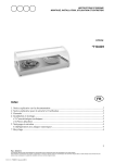
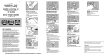
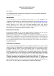
Informazioni per l’utente finale
g.
g.1
Informations pour l’usager final
Manutenzioni
Maintenance
Il bordo sensibile ACTIVE non necessita di manutenzioni
particolari, è consigliabile tuttavia effettuare un
controllo periodico (ogni 6 mesi).
Di ogni verifica deve essere mantenuta la registrazione
(vedi registro di manutenzione nel manuale utente)
E' buona norma asportare eventuali sostanze estranee
effettuando una pulizia con aspiratori.
Eventuali modifiche del dispositivo possono
determinare situazioni pericolose.
Qualsiasi intervento di manutenzione o taratura del
dispositivo dovrà essere effettuata da installatori
qualificati.
g.2
g.2.1
g.2.2
g.2.3
Risoluzione dei problemi
Le bord sensible ACTIVE ne nécessite de aucune
maintenance particulière, mais un contrôle périodique
(tous les 6 mois)e s t
recommandé.
Chaque contrôle doit être enregistré (voir le cahier de
maintenance dans le manuel de l'usager).
Il est bon d'emporter substances étrangères en
nettoyant avec aspirateurs.
Toutes modifications du dispositif peuvent provoquer
des situations dangereuses.
Les interventions de maintenance et tarage du
dispositif doivent être exécutées par des installateurs
qualifiés.
Information for the final user
Maintenance
ACTIVE safety edge does not need special maintenance,
yet a periodic check (every 6 months) is
recommended.
Each check must be registered (see maintenance
register in the user manual).
It is recommended to remove any extraneous
substances cleaning with exhausters.
ACTIVE
a.
Any device modification can cause dangerous
situations.
Any intervention of maintenance and calibration of the
device must be realized by qualified fitters.
Résolution des problèmes
Problems solution
Problema riscontrato:
Problème rencontré:
Problem found:
Bordo Sensibile non interviene
le bord sensible n'intervient pas
The safety edge does not intervene
Possibili cause:
Causes possibles:
Possible causes:
Guasto collegamenti
Liens défectueux
faulty links
Interventi da effettuare:
Opérations à réaliser:
Operation to be performed:
Porre l’automazione in «funzionamento manuale» e
rivolgersi all’assistenza
Placez l'automation en mode "manuel" et appelez le
support technique
Place the automation in "manual mode" and call for
service
Problema riscontrato:
Problème rencontré:
Problem found:
Bordo Sensibile interviene in ritardo
le bord sensible intervient en rétard
The safety edge intervenes late
Possibili cause:
Causes possibles:
Possible causes:
Tensionamento cavo acciaio insufficiente
Tension du câble en acier
Steel cable tension
Interventi da effettuare:
Opérations à réaliser:
Operation to be performed:
Rivolgersi all’assistenza
Appelez le support technique
Call for service
Problema riscontrato:
Problème rencontré:
Problem found:
Automatismo bloccato in posizione «aperta»
Automatisme bloqué en position “ouvert”
Automatic locked in “open” position
Possibili cause:
Causes possibles:
Bordo sensibile in allarme. Guasto sul collegamento
o perdita taratura
Bord de sécurité en état d'alarme. Problèmes de
connexions
Interventi da effettuare:
Opérations à réaliser:
Verificare che non vi siano oggetti che pongano il
bordo in «allarme» e rivolgersi all’assistenza
Vérifiez s'il y a des objets qui mettent le bord en
“alarm” et contactez le support technique
Operation to be performed:
Verify if there are objects that place the edge in
"alarm" Call for service
Registro delle manutenzioni
Cahier de maintenance
Maintenance register
MBS
b.
c.
Legenda e simboli
Légende des symboles
Key
Segnala le parti del manuale da leggere con attenzione
Il signale les parties du manuel qui doivent être
lues soigneusement
It indicates the parts of the manual to be read
carefully;
Segnala parti riguardanti la sicurezza
Il signale les parties qui concernent la sécurité;
It indicates the parts related to safety;
Segnala le informazioni dirette all' utente finale
(utilizzatore)
Il signale les informations adressées à l'usager
final (utilisateur)
It indicates the information aimed to the final user
(consumer)
Misura del Bordo Sensibile che si desidera ottenere
(calotte comprese)
Mesure du Bordo Sensible qu’on veut obtenir
(couvercle compris)
Safety Edge size you wish to obtain (cup included)
Destinazione d’uso
Destination d’usage
Destination of use
Il bordo sensibile ACTIVE viene utilizzato come dispositivo di
sicurezza in impianti di automazione per cancelli scorrevoli
a scorrimento orizzontale, a protezione di rischi di
schiacciamento ed intrappolamento. La deformazione
della gomma provoca l'intervento del bordo sensibile
lungo tutta la sua altezza.
Le bord sensible de sécurité ACTIVE est utilisé en tant
que dispositif de sécurité dans systèmes
d'automation pour portails coulissants à glissement
horizontal pour protéger contre risques
d'écrasement. La déformation du caoutchouc
provoque l'intervention du bord sensible sur toute
sa hauteur.
ACTIVE safety edge is used as a safety device in
automation systems for sliding gates in horizontal
sliding to protect against risks of crushing and
trapping. The rubber distortion causes the intervention
of the safety edge along its whole height.
Utilizzi diversi da quanto sopra descritto del bordo
sensibile ACTIVE o installazione non eseguita in conformità a
quanto descritto nel seguente manuale possono
pregiudicare il corretto funzionamento del dispositivo.
Utilisations du bord sensible ACTIVE différentes de ce
qui a été ci-dessus décrit ou installations pas
exécutées en conformité avec ce qui est décrit dans
ce manuel peuvent compromettre le correct
fonctionnement du dispositif.
Uses of ACTIVE safety edge which are different from
what above mentioned or installations which are not
realized according to what described in this manual
can compromise the right working of the device.
L' installazione del bordo sensibile ACTIVE dovrà essere
eseguita da installatori qualificati.
L'installation du bord sensible ACTIVE doit être
exécutée par installateurs qualifiés.
The installation of ACTIVE safety edge must be realized
by qualified fitters.
Descrizione
Description
Description
ll bordo sensibile ACTIVE va posizionato in sede verticale
avendo cura di montare la scheda con i microswitches
nella parte superiore.
Le bord ACTIVE doit être placé à la verticale, en
prenant soin de monter la carte avec les micros
dans la partie supérieure.
ACTIVE Sensitive edge must be positioned in the
vertical, taking care to mount the card with the
microswitches in the upper part.
Il bordo sensibile ACTIVE è formato da un' estruso in gomma
con dopocorsa elastico di ammortamento urto e da un
profilo in alluminio che fissato alla colonna o al cancello
funge da supporto all' estruso.
Il funzionamento del dispositivo è garantito da 2
microswitches. Entrambi lavorano su deformazione della
costa comprensiva delle calotte morbide poste alle
estremità e come sicurezza nel caso in cui il cavo di
acciaio dovesse perdere tensione.
Le bord ACTIVE est formé par un caoutchouc extrudé
avec après-course d'amortissement de choc
élastique et par un profilé en aluminium qui est fixé à
la colonne ou à la grille et qui agit comme un
support. Le fonctionnement du dispositif est garanti
par 2 micro-interrupteurs. Les deux travaillent sur la
déformation de la barre y compris les capuchons
souples aux extrémités et comme sécurité dans le
cas où le câble d'acier perd sa tension.
The safety edge ACTIVE is composed by an extruded
rubber with elastic after-run of amortization and an
aluminum profile that is fixed to the column or to the
gate and it acts as a support. The operation of the
device is guaranteed by 2 microswitches. Both work
on deformation of the edge including soft caps at the
ends if the steel cable lose tension.
Il bordo sensibile ACTIVE-C viene fornito nelle seguenti
misure [mm]:1000; 1500; 1700; 2000; 2500; 3000; 4000.
Le bord ACTIVE-C est fourni dans les dimensions
suivantes [mm]:1000; 1500; 1700; 2000; 2500;
3000; 4000.
The sensitive edge ACTIVE-C is available in the following
sizes [mm]:1000; 1500; 1700; 2000; 2500; 3000;
4000.
Caractéristiques techniques
Technical features
C.1
Possible causes:
Safety edge in alarm. failure connecting
C.2
h.
Manuale di Installazione
ACTIVE
Rev. 12-00
BORDO SENSIBILE
BORD SENSIBLE DE SECURITE
SAFETY EDGE
C.3
d.
Caratteristiche tecniche
.
Estruso morbido in TPE
Extrudé souple en TPE
Estruso rigido in alluminio
Extrudé rigide en aluminium
Parti rigide in nylon
Composants rigides en nylon
TPE soft extruded
Aluminium hard extruded
Nylon parts
18mm
Precorsa
Pré-course
Pre-run
24mm
Oltre corsa
Aprés-course
After-run
Velocità max di rilevamento
Vitesse max de relévement
Max. bearing speed
0,1sec
Tempo di risposta
Temps de réponse
Response time
< 2sec
Tempo di recupero deformazione
Temps de recouvrement
Distorsion recovery time
J1 NC
J1 R
Uscita contatto NC
Uscita contatto resistivo
Sortie contact NC
Sortie contact résistif
NC Contact output
Resistive Contact output
5A 250Vac
Portata Contatto
Portée Contact
Relay contact
8,2 KΩ
Valore resistenza
Valeur résistance
Resistance value
Temperatura d’esercizio
Température d’exercise
Working temperature
Grado di protezione
Degré de protection
Protection degree
TIMBRO DEL RIVENDITORE / TAMPON DU VENDEUR / DEALER STAMP
12m/min
Attenzione: Il dispositivo elettromeccanico di
rilevamento ostacoli ACTIVE è un dispositivo di
sicurezza “ausiliario”. Vale a dire che è
utilizzabile su impianti comandati a “uomo
presente” oppure in conformità ai requisiti
dettati dalla Norma di Sicurezza EN12453.
Pag. 4 - 4
Attention : le dispositif pour relèvement des
obstacles ACTIVE est un dispositif de sécurité
supplementaire. Le bord sensible doit être
utilisé sur des équipements contrôlés par un
opérateur ou en conformité à la Norme de
Securité EN12453.
Attention: the electromechanical device
ACTIVE is an “auxiliary” safety device. The
border must be used on equipments
controlled by an operator or according to the
standards of the Safety Standard EN 12453.
-10° +60°
IP54
Pag. 1 - 4
e.
Montaggio Bordo Sensibile
Montage du Bord Sensible
Safety Edge installation
L’installazione del Bordo Sensibile ACTIVE dovrà essere
eseguito da installatori qualificati
L’installation du Bord Sensible ACTIVE doit être
exécutée par installateurs qualifiée
The installation of ACTIVE Dafety Edge must be realized
by qualified fitters
Fissaggio della costa
Fixage de la barre
Fixing of the safety edge
e.2.1
Fissare le CLIP (DIS. 1 part. 1.1) alla colonna o al cancello
facendo riferimento alle quote riportare nella TAB 1 (H1.1
/ H 1.2 / H 1.3)
Fixer le CLIP (DIS. 1 part. 1.1.) à la colonne ou à la
grille en se référant à la TAB 1 (H1.1 / H 1,2 / H 1,3)
Fix the CLIP (DIS.1 part 1. 1) to the columnor to the
gate by reference to the shares back in TAB 1
(H1.1 / H 1.2 / H 1.3)
e.2.2
Inserire la costa nelle CLIP e fissarla alla colonna o al
cancello con i fori predisposti (DIS. 1 part. 1.2), vedi TAB
1 (H 2.1 / H 2.2)
Entrez la barre dans les CLIPS et fixez-la par les
trous à la colonne ou à la grille (DIS. 1 part. 1.2),
voir TAB 1 (H 2.1 / H 2.2)
Fit the edge to the CLIP in the column or in the gate
and secure with holes (DIS. part 1. 1.2), see TAB 1 (H
2.1 / H 2.2)
DIS. 1
DIS. 2
e.1
PART 2.1
e.2
e.3
e.4
Collegamento
Connexion
Connection
- Montato il Bordo Sensibile alla colonna o al cancello
eseguire i collegamenti della costa secondo lo schema
allegato (DIS. 2 part. 2.1)
- Il jumper J1 seleziona il tipo di contatto che si vuole
utilizzare sui morsetti di collegamento:
J1 NC = Contatto NC (DIS. 2 part. 2.2)
J1 R = Contatto resistivo 8,2 KΩ (DIS. 2 part. 2.3)
- Une fois assemblé le bord à la colonne ou à la
grille, effectuer les liens du bord selon le schéma cijoint (DIS. 2 part. 2.1).
- Le jumper J1 (DIS. 2) sélectionne le type de
contact que vous souhaitez utiliser avec les bornes
de raccordement:
J1 NC= Contact NC (DIS. 2 part. 2.2)
J1 R = Contact résistif 8.2KΩ (DIS. 2 part. 2.3)
- Once you have fix the safety edge to the coloumn or
to the gate, make connections to the edge, according
to the attached diagram (DIS. 2 part. 2.1)
- The jumper J1 (DIS. 2) selects the type of contact
that you want to use the connection terminals:
J1 NC= NC contact (DIS. 2 part. 2.2)
J1 R = Contact resistance 8,2KΩ (DIS. 2 part. 2.3)
PART 2.2
J1=NC
INGRESSO CAVI
ENTREE CABLES
CABLE ENTRY
PART 2.3
J1=8.2KΩ
PART 1.2
DIS. 3
Tensionatura cavo e taratura
Tension du cable et tarage
Cable tension and calibration
La costa viene già fornita con una pretensionatura del
cavo. E’ tuttavia possibile eseguire una ulteriore
regolazione della costa agendo sulla VITE (DIS. 3 part.3.1)
posta sul braccio del supporto superiore della costa.
Ruotando in senso orario si aumenterà la sensibilità della
costa (+)
Ruotando in senso antiorario si diminuirà la sensibilità
della costa (-)
La barre est déjà fournie avec le câble prétensioné.
Cependant il est possible effectuer un ajustement
de la barre en tournant la VIS (DIS. 3. part. 1.2)
placée sur le bras de la partie supérieure de la barre.
En tournant vers la droite la sensibilité de la barre va
augmenter (+)
Tournant vers la gauche la sensibilité de la barre va
diminuer (-)
The safety edge is already provided with the
pretensioned cable. And however, you can make
further adjustment by turning the SCREW (DIS. 3 part
1.2) on the arm of the upper support of the edge.
Turning clockwise will increase the sensitivity the
coast (+)
Turning counterclockwise will decrease the sensitivity
the coast (-)
PART 1.1
e.5
Inserimento delle calotte
Encastrement des capuchons
Positioning of the cap
- Per inserire la calotta morbida, posizionarla
frontalmente alla piastra di supporto, avendo cura di fare
scorrere le alette terminali nelle proprie sedi di
contenimento (DIS. 4 part.4.1) e i due ganci laterali di
bloccaggio all’interno delle feritoie predisposte (DIS. 4
part.4.2). Applicare una leggera pressione affinchè vi sia
uno scatto ad indicare il corretto collocamento della
stessa.
Fissare la calotta con la vite in dotazione (DIS. 4 part.4.3).
- Per rimuovere la calotta agire in maniera inversa: togliere
la vite di testa (DIS. 4 part. 4.3), sganciare la calotta
inserendo un utensile all’interno delle feritorie spingendo i
ganci verso l’interno.
- Pour encastrer le capuchon souple, le placer en
face de la plaque de support, en prenant soin de
faire glisser les extrémités libres dans leur sièges
(DIS.4 part. 4.1) et les deux crochets latérals de
blocage à l'intérieur des fentes disposées (DIS. 4
part. 4.2). Appliquez une légère pression pour qu'il y
ait un déclic pour indiquer le positionnement correct
du capuchon.
Fixez le capuchon avec la vis fournie (DIS. 4 part.
4.3).
- Pour retirer le capuchon agir en sens inverse:
enlever la vis (DIS. 4 part. 4.3), relâchez le capuchon
en insérant un outil à l'intérieur des fentes en
poussant les crochets vers l'intérieur.
- To insert the soft cap, place it in front of the support
plate, taking care to slide the flaps in their seats (DIS. 4
part. 4.1) and the two lateral locking hooks inside of
slits arranged (DIS. 4 part. 4.2). Apply light pressure so
that there is a click to indicate the correct placement of
the same. Secure the cover with the screw provided
(DIS 4 part. 4.3).
- To remove the cover please act in reverse: remove the
screw (DIS 4 part. 4.3), release the cap by inserting a
tool inside the slits pushing the hooks inward.
Nota
Note
Note
Allo scopo di migliorare lo scarico di eventuali sedimenti
che potrebbero formarsi all’interno della calotta inferiore è
consigliabile praticare un foro come indicato nel DIS.4
(part 4.4).
Afin d'améliorer l'évacuation de tout sédiment In order to improve the discharge of any sediment that
pouvant se former à l'intérieur du capuchon inférieur may find inside the bottom cap, it is advisable to drill a
il est conseillé de percer un trou commeil est indiqué hole as shown in DIS 4( part 4.4).
ci-après en DIS.4 (partie 4.4).
Quote fissaggio Bordo Sensibile
Niveaux de fixation du Bord Sensible
+
PART 1.1
PART 3.1
PART 1.1
DIS. 4
PART 4.1
TAB. 1
Altezza foro fiss. CLIP (mm)
Hauteur trou fixation CLIP(mm)
Height of the fixing hole for CLIP
H 1.1
1.000mm
H 1.2
Altezza foro fiss. SUPPORTI (mm)
Hauteur trou fixation SUPPORTS (mm)
(mm )
Height of the fixing hole for SUPPORTS (mm)
H 1.3
H 2.1
500
1.700mm
H 2.2
978
1300
1.500mm
1478
1500
1800
2.500mm
1250
2300
2478
3.000mm
1500
2800
2978
4.000mm
2000
3800
3978
200
PART 4.2
PART 1.2
1678
1000
2.000mm
Pag. 2 - 4
Safety Edge fastening figures
22
1978
PART 4.3
PART 4.4 Ø5mm
Pag. 3 - 4