1
UEP 48
Universal Eprom Programmer 48 pin
MANUALE UTENTE
USER MANUAL
Via dell' Artigiano, 8/6
® 40016 San Giorgio di Piano
(Bologna) ITALY
ITALIAN TECHNOLOGY
E-mail: [email protected]
http://www.grifo.it
http://www.grifo.com
Tel. +39 051 892.052 (a.r.) FAX: +39 051 893.661
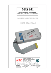
UEP 48
Edition 3.10
Rel 14 December 2000
, GPC®, grifo®, are trade marks of grifo®
grifo
UEP 48
Universal Eprom Programmer 48 pin
MANUALE UTENTE
USER MANUAL
UEP 48 è un potente programmatore e tester per IC logici dotato di 48
pindrivers effettivi. Questo criterio di progetto permette di aggiungere
facilmente nuovi dispositivi alla lista di quelli programmabili.
UEP 48 è un autentico programmatore universale a basso costo che
realizza il miglior investimento nel tempo per il mercato attuale.
UEP 48 is a universal programmer and logic IC tester with 48 powerful
pindrivers. This design allows to easily add new devices to the device list.
UEP 48 is a true universal and a true low-cost programmer, providing the
best “value for money” in today’s market.
Via dell' Artigiano, 8/6
® 40016 San Giorgio di Piano
(Bologna) ITALY
ITALIAN TECHNOLOGY
E-mail: [email protected]
http://www.grifo.it
http://www.grifo.com
Tel. +39 051 892.052 (a.r.) FAX: +39 051 893.661
UEP 48
Edition 3.10
Rel 14 December 2000
, GPC®, grifo®, are trade marks of grifo®
grifo
DOCUMENTATION COPYRIGHT BY grifo® , ALL RIGHTS RESERVED
No part of this document may be reproduced, transmitted, transcribed, stored in a
retrieval system, or translated into any language or computer language, in any form or
by any means, either electronic, mechanical, magnetic, optical, chemical, manual, or
otherwise, without the prior written consent of grifo®.
IMPORTANT
Although all the information contained herein have been carefully verified, grifo®
assumes no responsability for errors that might appear in this document, or for damage
to things or persons resulting from technical errors, omission and improper use of this
manual and of the related software and hardware.
grifo® reserves the right to change the contents and form of this document, as well as the
features and specification of its products at any time, without prior notice, to obtain
always the best product.
For specific informations on the components mounted on the card, please refer to the
Data Book of the builder or second sources.
SYMBOLS DESCRIPTION
In the manual could appear the following symbols:
Attention: Generic danger
Attention: High voltage
Trade Marks
, GPC®, grifo® : are trade marks of grifo®.
Other Product and Company names listed, are trade marks of their respective companies.
ITALIAN TECHNOLOGY
grifo®
INDICE GENERALE
INTRODUZIONE ........................................................................................................................ 1
INFORMAZIONI GENERALI .................................................................................................. 2
CONVENZIONI E TERMINOLOGIA................................................................................. 2
CONVENZIONI ................................................................................................................. 2
TERMINOLOGIA ............................................................................................................. 2
CARATTERISTICHE GENERALI ........................................................................................... 3
INTRODUZIONE ................................................................................................................... 3
CARATTERISTICHE TECNICHE ........................................................................................... 6
ELEMENTI DI UEP 48 .......................................................................................................... 6
SPECIFICHE TECNICHE .................................................................................................... 6
FORMATI SUPPORTATI ...................................................................................................... 6
TEMPI DI PROGRAMMAZIONE ....................................................................................... 7
OPERAZIONI SU DISPOSITIVI .......................................................................................... 7
OPERAZIONI SUL BUFFER ................................................................................................ 7
FORMATI DI FILE SUPPORTATI ...................................................................................... 7
GENERALI .............................................................................................................................. 7
CONTENUTO DELLA CONFEZIONE ............................................................................... 8
INSTALLAZIONE ..................................................................................................................... 10
CONNESSIONE DI UEP 48 COL PC ................................................................................. 10
PROBLEMI DI COLLEGAMENTO UEP 48 E PC .......................................................... 11
LEDS ....................................................................................................................................... 11
SELFTEST E CALIBRAZIONE ......................................................................................... 11
INSTALLAZIONE DEL PROGRAMMA DI CONTROLLO .......................................... 13
CONFIGURAZIONE MINIMA DEL PC ........................................................................... 13
CONFIGURAZIONE CONSIGLIATA DEL PC ................................................................ 13
INSTALLAZIONE SOFTWARE ......................................................................................... 13
NUOVE VERSIONI DEL PROGRAMMA DI CONTROLLO ........................................ 14
AGGIORNARE IL PROGRAMMA DI CONTROLLO ................................................... 14
AVVIO RAPIDO......................................................................................................................... 15
INSTALLAZIONE HARDWARE ....................................................................................... 15
INSTALLAZIONE DEL PROGRAMMA DI CONTROLLO .......................................... 16
PROGRAMMARE O COPIARE UN DISPOSITIVO ...................................................... 16
DESCRIZIONE SOFTWARE ................................................................................................... 17
UTILIZZO DEL SOFTWARE ............................................................................................. 17
DESCRIZIONE DELLA SCHERMATA PRINCIPALE ................................................... 17
LISTA DEI TASTI SPECIALI ............................................................................................. 18
UEP 48
Rel. 3.10
Pagina I
grifo®
ITALIAN TECHNOLOGY
COMANDI DEL PROGRAMMA DI CONTROLLO ....................................................... 19
MENU DEVICE ............................................................................................................... 19
SOTTOMENU DEVICE OPTIONS ............................................................................... 22
MENU FILE ...................................................................................................................... 23
MENU BUFFER ............................................................................................................... 23
MENU OPZIONI .............................................................................................................. 24
MENU QUIT .......................................................................................................................... 27
MENU ABOUT ................................................................................................................. 28
MENU DIAGNOSTICS ........................................................................................................ 28
SELFTEST ........................................................................................................................ 28
SELFTEST PLUS ............................................................................................................. 28
IC TEST ............................................................................................................................. 28
HELP ...................................................................................................................................... 28
TERMINI DELLA GARANZIA ............................................................................................... 30
RISOLUZIONE DEI PROBLEMI ........................................................................................... 31
ERRORI DI COMUNICAZIONE ....................................................................................... 31
PROLEMI DI LETTURA O PROGRAMMAZIONE ....................................................... 31
DISPOSITIVI NON SUPPORTATI..................................................................................... 32
DISPOSITIVI ADDIZIONALI ................................................................................................. 33
MODULI ADATTATORI ..................................................................................................... 34
CONVERTITORI DI FORMATO ....................................................................................... 35
INDICE ANALITICO ................................................................................................................ 36
Pagina II
UEP 48
Rel. 3.10
ITALIAN TECHNOLOGY
grifo®
INDICE DELLE FIGURE
FIGURA 1: FOTO UEP 48 ................................................................................................................. 5
FIGURA 2: CONTENUTO DELLA CONFEZIONE ...................................................................................... 9
FIGURA 3: DESCRIZIONE LEDS DEL'UEP 48 ................................................................................. 11
FIGURA 4: POSIZIONE LEDS, PULSANTE E ZOCCOLO ....................................................................... 12
FIGURA 5: CONNETTORE LPT ........................................................................................................ 12
FIGURA 6: CONNESSIONE LPT E ALIMENTAZIONE ........................................................................... 12
FIGURA 7: POD DIAGNOSTICO PER IL SELFTEST .............................................................................. 12
FIGURA 8: TABELLA MODULI ADATTATORI ....................................................................................... 34
FIGURA 9: TABELLA CONVERTITORI DI FORMATO ............................................................................. 35
UEP 48
Rel. 3.10
Pagina III
grifo®
ITALIAN TECHNOLOGY
GENERAL INDEX
GENERAL INTRODUCTION .................................................................................................. 39
PRELIMINARY INFORMATION ........................................................................................... 40
CONVENTIONS AND TERMINOLOGY .......................................................................... 40
CONVENTIONS USED IN THE MANUAL ................................................................. 40
TERMINOLOGY USED IN THE MANUAL ................................................................ 40
GENERAL FEATURES ............................................................................................................. 41
INTRODUCTION ................................................................................................................. 41
TECHNICAL FEATURES ........................................................................................................ 44
UEP 48 ELEMENTS ............................................................................................................. 44
TECHNICAL SPECIFICATION ......................................................................................... 44
PACKAGE SUPPORT .......................................................................................................... 44
PROGRAMMING SPEED ................................................................................................... 45
DEVICE OPERATIONS ...................................................................................................... 45
BUFFER OPERATIONS ...................................................................................................... 45
SUPPORTED FILE FORMATS .......................................................................................... 45
GENERAL ............................................................................................................................. 45
PACKAGE INCLUDED ....................................................................................................... 46
INSTALLATION ........................................................................................................................ 48
CONNECTING UEP 48 TO THE PC ................................................................................. 48
PROBLEMS RELATED TO UEP 48 TO PC CONNECTION ......................................... 49
LEDS ....................................................................................................................................... 49
SELFTEST AND CALIBRATION ...................................................................................... 49
INSTALLING PROGRAMMER SOFTWARE ................................................................. 51
MINIMAL PC CONFIGURATION .................................................................................... 51
RECOMMENDED PC CONFIGURATION ...................................................................... 51
SOFTWARE INSTALLATION ............................................................................................ 51
NEW VERSIONS OF PROGRAMMER SOFTWARE ..................................................... 52
UPGRADING THE PROGRAMMER SOFTWARE ........................................................ 52
QUICKSTART ............................................................................................................................ 53
INSTALLING PROGRAMMER HARDWARE ................................................................ 53
INSTALLING OF PROGRAMMER SOFTWARE ........................................................... 54
QUICK INSTRUCTIONS TO PROGRAM OR COPY A DEVICE ................................ 54
SOFTWARE DESCRIPTION ................................................................................................... 55
USING THE PROGRAMMER SOFTWARE .................................................................... 55
DESCRIPTION OF THE USER SCREEN ......................................................................... 55
LIST OF HOT KEYS ............................................................................................................ 56
CONTROL PROGRAM COMMANDS .............................................................................. 57
Pagina IV
UEP 48
Rel. 3.10
ITALIAN TECHNOLOGY
grifo®
DEVICE MENU ............................................................................................................... 57
DEVICE OPTIONS SUBMENU ..................................................................................... 60
FILE MENU ...................................................................................................................... 61
BUFFER MENU ............................................................................................................... 61
OPTIONS MENU ............................................................................................................. 62
QUIT MENU ..................................................................................................................... 65
ABOUT MENU ................................................................................................................. 66
DIAGNOSTICS MENU ................................................................................................... 66
SELFTEST ........................................................................................................................ 66
SELFTEST PLUS ............................................................................................................. 66
IC TEST ............................................................................................................................. 66
HELP SYSTEM ..................................................................................................................... 66
WARRANTY TERMS ............................................................................................................... 68
TROUBLESHOOTING ............................................................................................................. 69
COMMUNICATION ERRORS ........................................................................................... 69
READING OR PROGRAMMING PROBLEMS .............................................................. 69
UNSUPPORTED TARGET DEVICE ................................................................................. 70
ADDITIONAL TOOLS .............................................................................................................. 71
ADAPTER MODULES ......................................................................................................... 72
PACKAGE CONVERTERS ................................................................................................. 73
ALPHABETICAL INDEX ........................................................................................................ 74
UEP 48
Rel. 3.10
Pagina V
grifo®
ITALIAN TECHNOLOGY
FIGURES INDEX
FIGURE 1: UEP 48 PHOTO ............................................................................................................. 43
FIGURE 2: PACKAGE CONTENT ........................................................................................................ 47
FIGURE 3: UEP 48 LEDS DESCRIPTION TABLE ............................................................................... 49
FIGURE 4: LEDS, BUTTON AND TEXTOOL LOCATION ........................................................................ 50
FIGURE 5: LPT AND SUPPLY SOCKETS ............................................................................................. 50
FIGURE 6: LPT AND SUPPLY CONNECTION ....................................................................................... 50
FIGURE 7: SELFTEST DIAGNOSTIC POD .......................................................................................... 50
FIGURE 8: ADAPTER MODULES TABLE .............................................................................................. 72
FIGURE 9: PACKAGE CONVERTERS TABLE ......................................................................................... 73
Pagina VI
UEP 48
Rel. 3.10
ITALIAN TECHNOLOGY
grifo®
INTRODUZIONE
Scopo di questo manuale é la trasmissione delle informazioni necessarie all’uso competente e sicuro
dei prodotti. Esse sono il frutto di un’elaborazione continua e sistematica di dati e prove tecniche
registrate e validate dal Costruttore, in attuazione alle procedure interne di sicurezza e qualità
dell'informazione.
Per un corretto rapporto coi prodotti, é necessario garantire leggibilità e conservazione del manuale,
anche per futuri riferimenti. In caso di deterioramento o più semplicemente per ragioni di
approfondimento tecnico ed operativo, consultare i nostri siti www.grifo.it o www.grifo.com o
direttamente l’Assistenza Tecnica autorizzata.
Al fine di non incontrare problemi nell’uso di tali dispositivi, é conveniente che l’utente - PRIMA
DI COMINCIARE AD OPERARE - legga con attenzione tutte le informazioni contenute in questo
manuale. In una seconda fase, per rintracciare più facilmente le informazioni necessarie, si può fare
riferimento all’indice generale e all’indice analitico, posti rispettivamente all’inizio ed alla fine del
manuale.
Le informazioni contenute in questo manuale sono aggiornate alla data di rilascio del medesimo, ma
i nostri prodotti subiscono continui aggiornamenti e miglioramenti. Si prega di consultare il file
README_P.TXT per i cambiamenti dell'ultimo minuto.
Il programmaqui descritto è coperto da diritto d'autore, tutti i diritti sono riservati. Nè il programma
nè alcuna sua parte possono essere analizzati, disassemblati o modificati in alcun modo, con
qualunque mezzo, per qualunque scopo.
Questo documento è coperto da diritto d'autore, tutti i diritti sono riservati. Questo documento non
può essere copiato, riprodotto o tradotto in alcun modo o mediante alcun mezzo, nè per intero nè in
parte, senza il permesso scritto della grifo®.
grifo® non si assume alcuna responsabilità per l'uso errato di questo manuale.
grifo® si riserva il diritto di apportare cambiamenti o miglioramenti ai prodotti descritti in questo
manuale in qualunque momento senza darne notizia.
Questo manuale contiene nomi di aziende, software, prodotti, ecc. che sono marchi registrati dai
rispettivi propietari. grifo® rispetta tale diritto.
UEP 48
Rel. 3.10
Pagina 1
grifo®
ITALIAN TECHNOLOGY
INFORMAZIONI GENERALI
Questo manuale spiega come installare il programma di controllo e come usare il vostro programmatore.
Si assume che l'utente abbia una minima esperienza con il PC e l'installazione di software, sebbene
il capitolo “AVVIO RAPIDO” vi potrà guidare passo dopo passo attraverso l'intero processo di
installazione.
Una volta installato il programma di controllo vi consigliamo di consultare l'help in linea sensibile
al contesto piuttosto che il Manuale Utente poichè le revisioni vengono introdotte prima nel
programma che nel Manuale.
Tutti i programmatori qui descritti funzionano con quasi tutti i PC compatibili IBM, dall'XT al
Pentium Pro. Non si richiede alcuna scheda di interfaccia speciale per il collegamento col PC poichè
i programmatori si collegano tramite la porta parallela (stampante) del PC.
Tutti i programmatori funzionano correttamente con sistemi che hanno installati DOS, Windows 3.x,
Windows 95/98 e Windows NT/2000.
Tutti i programmatori sono controllati mediante un programma facile da usare con menù a tendina,
tasti scorciatoia e help in linea. Vi sono due versione del programma di controllo: PG4U per DOS
e PG4UW per Windows 95/98/NT/2000. Il programma di controllo è comune per tutti i programmatori
(UEP 48, EP 32, MP AVR-51, MP PIK e SEEP).
CONVENZIONI E TERMINOLOGIA
Vengono usati in questo manuale alcune convenzioni e termini speciali:
CONVENZIONI
I riferimenti alle funzioni del programma di controllo sono in maiuscolo, ad esempio
LOAD FILE, ecc. I riferimenti ai tasti speciali sono scritti in parentesi angolari <>, ad
esempio <F1>.
TERMINOLOGIA
Dispositivo target
zoccolo ZIF
BUFFER
Porta parallela
formato HEX
Pagina 2
Qualunque tipo di circuito integrato o dispositivo programmabile con
questi programmatori.
Zoccolo senza sforzo d'inserzione (Zero Insertion Force) usato
per ospitare il dispositivo da programmare.
Spazio su disco o in memoia usato per memorizzazioni temporanee.
Tipo di porta del PC (porta stampante), dedicata principalmente alla
connessione dei dispositivi paralleli (stampanti ecc.).
Formato di file di dati che può essere letto da comuni visualizzatori
di testo; esempio il byte 5AH viene rappresentato dai caratteri '5'
ed 'A', cioè dai bytes 35H e 41H. Una riga di un file HEX (un
record) contiene indirizzo iniziale, bytes di dati e checksum.
UEP 48
Rel. 3.10
ITALIAN TECHNOLOGY
grifo®
CARATTERISTICHE GENERALI
Questo capitolo contiene una descrizione completa ed esauriente del programmatore, compreso un
riassunto delle sue caratteristiche tecniche ed operative.
INTRODUZIONE
UEP 48 è un programmatore universale ed un tester per circuiti logici con pilotaggio indipendente
dei 48 pin. Questo concetto di progettazione permette di estendere facilmente la lista dei dispositivi
programmabili. UEP 48 è un vero programmatore universale a basso costo, in grado di fornire il
miglior rapporto prezzo/prestazioni nei confronti del mercato moderno.
UEP 48 è un programmatore universale che supporta i circuiti integrati o dispositivi programmabili
realizzati usando varie tecnologie. Il potente controllo elettronico fornisce, indipendentemente su
ognuno dei 48 pin, livelli logici, pull up/pull down, clock, ground, una alimentazione e due tensioni
di programmazione, inoltre è in grado di leggere i 48 pin indipendentemente. Questa progettazione
avanzata permette all'UEP 48 di gestire quasi ogni dispositivo programmabile in DIL fino a 48 pin
senza bisogno di adattatori specifi o moduli convertitori. Essendo possibile aggiungere con facilità
nuovi dipositivi, viene data all'utente la libertà di includere sempre la migliore scelta nei propri
progetti.
UEP 48 è anche un tester per circuiti logici TTL/CMOS e vari tipi di memoria. Inoltre può generare
sequenze di test definibili dall'utente. UEP 48 è realmente un programmatore universale ed a basso
costo, in grado di fornire il miglior rapporto prezzo/prestazioni nei confronti del mercato moderno.
UEP 48 funziona praticamente con tutti i PC compatibili IBM, dall'XT al Pentium Pro. Sono state
fatte varie prove su diverse marche di computer ottenedo sempre ottime prestazioni di funzionamento,
sebbene si consigli l'uso di computer portatili dotati di porta parallela perfettamente compatibile
Centronics. Non servono schede specifiche di interfaccia, l'UEP 48 si collega alla porta parallela
compatibile Centronics dei PC, supportando anche il protocollo bidirezionale.
Il programmatore è dotato di un potente microprocessore a bordo e di dispositivi di controllo, inoltre
è stato progettato per funzionare con sistemi operativi multitasking ed è in grado effettuare
operazioni time-critical indipendentemente dal PC e senza poter essere interrotto da altri eventi
provenienti dalla porta parallela. Di conseguenza UEP 48 funziona senza problemi con Windows
3.x, Windows 95/98 e, in futuro, Windows NT/2000.
UEP 48 effettua il test di inserzione (posizione errata o capovolta) ed il controllo contatti (scarso
contatto elettrico tra pin e socket) per ogni dispositivo prima di programmarlo. Queste caratteristiche,
integrate dalla limitazione di corrente e dal controllo del byte di signature, aiutano a prevenire danni
ai chip causati da errori dell'operatore, i circuiti di protezione incorporati aiutano ad evitare danni
causati da fluttuazioni dell'alimentazione, errori di comunicazione o errori del sistema operativo. In
uno di questi casi UEP 48 effettua sequenze speciali di operazioni volte a proteggere il dispositivo.
UEP 48 può effettuare anche un test auto-diagnostico che verfica anche il livello di tensione ai pin,
l'accuratezza delle temporizzazioni e l'affidabilità della comunicazione col PC.
UEP 48 effettua verifiche della programmazione ai livelli minimi di tensione di alimentazione, in
modo da migliorare la resa della programmazione e la durata dei dati.
UEP 48
Rel. 3.10
Pagina 3
grifo®
ITALIAN TECHNOLOGY
UEP 48 incorpora criteri ottimali di progetto del PCB per minimizzare effetti indesiderati ai pin del
socket (come rimbalzi di massa o picchi nelle tensioni di alimentazione/programmazione). Tutti gli
ingressi di UEP 48, compreso il socket, sono protetti contro ESD e una volta inserito il dispositivo
da programmare questo viene protetto anche dai danni causati da ESD.
UEP 48 viene pilotato da un programma di controllo facile da usare, con menu a tendina, help in linea
e abbreviazioni dei comandi. Potete scegliere il dispositivo da programmare in base al tipo, il
costruttore o semplicemente da una frazione del part number. Per coadiuvare i tipici comandi
operativi sui dispositivi (blank check, lettura, programmazione, verifica) sono state implementate
delle funzioni di controllo (test di inserzione, test bit di protezione) ed alcune funzioni speciali
(modalità di produzione - inizia le operazioni immediatamente dopo avere inserito il dispositivo
nello zoccolo ZIF). Il programma di controllo permette di effettuare manipolozione del buffer e tra
buffer e files associati, con rilevamento e conversione automatica del formato.
Il programma di controllo fornisce una funzione di auto-incremento che permette di assegnare un
numero di serie individuale ad ogni dispositivo programmato, la funzione semplicemente incrementa
il numero di serie nel buffer ogni volta che un nuovo dispositivo viene inserito nello zoccolo. La
stessa funzione permette di leggere il numero di serie e la signature da un file.
Sono disponibili vari convertitori di formato per l'UEP 48; da DIL a PLCC, da DIL a PSOP, da DIL
a SOIC, da DIL a TQFP e da DIL a TSOP. La capacità di programmare dispositivi in qualsiasi
formato viene data all'UEP 48 dalla possibilità di scambiare le funzioni di due pin e dagli adattatori
universali. Per esempio, con un solo convertitore da DIL44 a PLCC44 si portanno gestire tutti i
dispositivi PLCC44 nella lista attuale. La maggior parte dei dispositivi con più di 48 pin richiedono
solo un semplice adattatore normalmente disponibili dalla grifo® o facilmente auto-costruibili
tramite le informazioni fornite nel file adapters.txt fornito col programma di controllo.
Considerate che la maggior parte dei dispositivi con più di 48 pin usano meno di 48 pin durante la
programmazione, quindi non creano problemi all'UEP 48.
Considerate inoltre che, nella maggior parte dei casi, aggiungere un nuovo dispositivo significa solo
aggiornare il software dell'UEP 48 grazie ai 48 pin driver che consentono la massima flessibilità in
fase di programmazione. Bastano poche ore per aggiungere un nuovo dispositivo!
La progettazione avanzata, i circuiti di protezione, i componenti originali di marca ed un attento
processo produttivo ci consentono di fornire una garazia di tre anni di funzionamento degli elementi
per UEP 48 (con un limite di 25.000 utilizzazioni dello zoccolo ZIF).
Pagina 4
UEP 48
Rel. 3.10
ITALIAN TECHNOLOGY
grifo®
FIGURA 1: FOTO UEP 48
UEP 48
Rel. 3.10
Pagina 5
grifo®
ITALIAN TECHNOLOGY
CARATTERISTICHE TECNICHE
ELEMENTI DI UEP 48
-
Zoccolo ZIF (Zero Insertion Force) 48 pin
LED alimentazione/sospensione
LEDs indicanti l'esito delle operazioni
Pulsante YES!
Connettore per cavo comunicazione PC <-> UEP 48
Connettore di alimentazione
SPECIFICHE TECNICHE
- Lo zoccolo ZIF da 48 pin DIL accetta dispositvi da 300/600 mil fino a 48 pin
- 3 convertitori D/A per VCCP, VPP1, e VPP2, con tempi di salita e discesa controllabili e
limitazione di corrente
- Il driver TTL fornisce H, L, CLK, pull-up, pull-down, o tri-state su tutti i 48 pins
- Pieno supporto per i ciruiti a bassa tensione da 1.8 V in su
- Autocalibrazione
- EPROM: NMOS/CMOS, serie 27xxx e 27Cxxx, da 16Kbit a 32Mbit con 8/16 bit larghezza bus
dati, pieno supporto alla serie LV
- EEPROM: NMOS/CMOS, serie 28xxx, 28Cxxx, 27EExxx, con 8/16 bit larghezza bus dati
- Flash EPROM: serie 28Fxxx, 29Cxxx, 29Fxxx, 29BVxxx, 29LVxxx, 29Wxxx, 49Fxxx, da
256Kbit a 32Mbit, con 8/16 bit larghezza bus dati, pieno supporto alla serie LV
- Serial E(E)PROM: serie 17Cxxx, 24Cxxx, 24Fxxx, 25Cxxx, 59Cxxx, 85xxx, 93Cxxx,
NVM3060, MDAxxx, pieno supporto alla serie LV
- PROM: Harris, NS, Philips, Tesla, TI
- NV RAM: Dallas DSxxx, SGS/Inmos, MKxxx
- PLD: serie AMD PALCE, GALs, PEELs
- Microcontrollori famiglia 48: serie 87x41, 87x42, 87x48, 87x49, 87x50
- Microcontrollori famiglia 51: serie 87xx, 87Cxxx, 87LVxx, 89Cxxx, 89Sxxx, 89LVxxx,
Philips 87C748..752
- Microcontrollori Microchip PIC: serie PIC12xxx, PIC16xxx, PIC17Cxxx, PIC18xxx
- Microcontrollori Atmel AVR: serie AT90Sxxxx
- Microcontrollori NEC (uPD78Pxxx series), SGS-Thomson (serie ST6), Zilog (serie Z8), ecc.
- TTL: serie 54,74 S/LS/ALS/H/HC/HCT
- CMOS: serie 4000, 4500
- Static RAM: 6116 .. 624000
- Pattern di test definibile dall'utente
FORMATI SUPPORTATI
- I formati supportati sono: DIP, PLCC, SDIP, SOIC, PSOP, TSOP, TQFP e altri (chiedete i
convertitori di formato)
- Supporta tutti i dispositivi in DIP tramite lo zoccolo di detault ZIF 48
- Supporta i formati PLCC28, PLCC32 e PLCC44 grazie all'adattatore universale (accessorio
opzionale da ordiare separatamente)
- Compatibie con alcun adattari di terze parti per il supporto non-DIP
Pagina 6
UEP 48
Rel. 3.10
ITALIAN TECHNOLOGY
grifo®
TEMPI DI PROGRAMMAZIONE
- M27C256, programmazione e verifica, PC486/DX50: 10 secondi
- M27C010, programmazione e verifica, PC586/100: 38 secondi
- AT29C040, programmazione e verifica, PC586/100: 120 secondi
OPERAZIONI SU DISPOSITIVI
-
Standard
Basata su selezione automatica dell'ID per EPROM/Flash EPROM
Blank check
Lettura
Programmazione
Verifica
Cancellazione
Configurazione dei bit di protezione
Test illegal bit
Checksum
Sicurezza
Test di inserzione
Controllo dei contatti
Controllo ID byte
Funzioni speciali
Modo produzione (inizio automatico immediatamente successivo all'insezione)
Incremento automatico del numero di serie del dispositivo
OPERAZIONI SUL BUFFER
-
View/edit, find/replace
Fill/copy, move, byte swap, word/dword split
Checksum (byte, word)
Print
FORMATI DI FILE SUPPORTATI
- Non formattato (binario)
- HEX: Intel, Intel EXT, Motorola S, MOS, Exormax, Tektronix, ASCII-SPACE-HEX
- JEDEC (ver. 3.0.A)
GENERALI
-
Tensione di funzionamento 12.15V AC/max.1.6A (alimentatore 220VAC/12VAC compreso)
Consumo di energia - max. 20W in funzione, circa 1W in sospensione
Dimensioni 275x157x70 mm
Peso (senza adattatori) 1.5 kg
Temperatura di funzionamento 5÷40 deg C
Umidità 20%.80%, senza condensa
UEP 48
Rel. 3.10
Pagina 7
grifo®
ITALIAN TECHNOLOGY
CONTENUTO DELLA CONFEZIONE
-
Programmatore
POD diagnostico, che permette di fare l'auto-diagnosi del programmatore
Cavo di connessione col PC lungo 1.8 m (6 ft.)
Alimentatore 220VAC/12VAC
Floppy disk 3.5" con il manuale utente in formato .pdf
Floppy disk 3.5" con il software di controllo
Confezione
Pagina 8
UEP 48
Rel. 3.10
ITALIAN TECHNOLOGY
grifo®
FIGURA 2: CONTENUTO DELLA CONFEZIONE
UEP 48
Rel. 3.10
Pagina 9
grifo®
ITALIAN TECHNOLOGY
INSTALLAZIONE
CONNESSIONE DI UEP 48 COL PC
Fate riferimento alla figura 6. Spegnete PC e programmatore. Inserite il cavo di comunicazione
fornito in una porta parallela libera del vostro PC. Rimuovete un cavo per stampante evenutalmente
già presente. Collegate l'altra estremità all'UEP 48. Stringete le viti dei connettori, questo è molto
importante. Anche se potete trovare che è scomodo dover ogni volta staccare il cavo della stampante
e ricollegare quello dell'UEP 48, dovete comunque considerare che non è possibile collegare il
programmatore tramite un data switch, sia meccanico che elettronico. Potete comunque installare
una scheda supplementare di I/O per dedicare una porta, esempio LPT2, all'UEP 48, mentre la
stampante può rimanere sulla porta LPT1.
Collegate l'alimentatore fornito in dotazione alla presa di alimentazione di rete e collegate il
connettore mini DIN alla presa di alimentazione etichettata “12 VAC” dell'UEP 48. Appena
colllegata l'alimentazione tutti i LED si accendono simultaneamente, poi i tre LED di stato si
spengono e si riaccendono in sequenza uno dopo l'altro, infine il LED di alimentazione si pone in
bassa luminosità, a questo punto l'UEP 48 è pronto a ricevere comandi. Accendete anche il PC e fate
partire il programma di controllo.
! ATTENZIONE !
Se non volete spegnere il PC mentre collegate il programmatore, procedete come segue:
- Quando connettete il programmatore al PC: PRIMA inserite il cavo di comunicazione
POI il connettore di alimentazione.
- Quando scollegate il programmatore dal PC: PRIMA scollegate il connettore di alimentazione
POI il cavo di comunicazione.
Dal punto di vista del programmatore la sequenza di collegamento e scollegamento è irrilevante, i
circuiti di protezione lo tengono al sicuro, ma ciò non vale per il vostro PC.
NOTA
Quando l'UEP 48 non viene usato, il programma di controllo commuta il programmatore in
sospensione (sleep mode), in questo stat il consumo è meno di 1 W per cui il programmatore non ha
un interruttore di spegnimento. Quando il LED di alimentazione è acceso a bassa intensità il
programmatore è in sospensione. L'elettronica incorporata nell'UEP 48 protegge il programmatore
stesso ed il dispositivo da programmare contro assenze di alimentazione lunghe o brevi e, in parte,
contro malfunzionamenti del PC. Non è possibile, comunque, garantire l'integrità del dispositivo da
programmare se l'utente inserisce parametri errati nel programma di controllo. Il dispositivo target
può non essere distrutto da interruzioni forzate del programma di controllo (reset o spegnimento del
PC) o dalla rimozione della connessione fisica col programmatore ma il suo contenuto può rimanere
indefinito. Non togliete il dispositivo target dallo zoccolo ZIF durante l'accesso da parte di UEP 48,
ovvero quando il LED BUSY è acceso.
Pagina 10
UEP 48
Rel. 3.10
grifo®
ITALIAN TECHNOLOGY
PROBLEMI DI COLLEGAMENTO UEP 48 E PC
A causa della grande varietà di porte parallele esistenti, può capitare che il programmatore non riesca
ad intendersi con il PC. Il problema può manifestarsi come comunicazione tra PC e programmatore
indaffidabile o del tutto assente.
- Se si verifica questo comportamento, provate a collegare il programmatore ad altre porte
parallele o ad altri PC.
- Ricordate che la porta parallela alla quale è connesso il programmatore deve essere configurata
come compatibile Centronics. Per verificare la configurazione il modo migliore è entrare nel
BIOS del vostro computer e vedere se la porta è impostata come compatibile (o standard, o
normale o SPP; a seconda del produttore del BIOS che state usando si trovano nomi diversi per
indicare la stessa cosa) o, se usate una scheda multi I/O, assicuratevi che sia configurata come
compatibile Centronics.
Se non trovate una soluzione, potete contattare la grifo® direttamente. Preparatevi a dare una
descrizione precisa della configurazione del vostro PC ed una descrizione del problema che vi è
capitato. Non va tralascitao il tipo di PC, il produttore, la velocità, il sistema operativo e la versione,
programmi residenti e la configurazione della porta parallela.
LEDS
L'UEP 48 è fornito di 4 LEDs per visualizzare lo stato dell'alimentazione e lo stato interno del
programmatore. Riferitevi agli elementi 2 e 3 nella figura 4 per localizzare i LEDs.
LED
COLORE
DESCRIZIONE
LED alimentazione
(raggio 5 mm)
Verde
All'accensione si illumina per alcuni secondi, poi
si spegne.
LED “BUSY”
Rosso
Quando è acceso indica che il programmatore sta
accedendo al dispositivo target in lettura o
scrittura. Non rimuovete il dispositivo target
quando questo LED è acceso.
LED “GOOD”
Verde
Quando è acceso questo LED indica che l'ultima
operazione è andata a buon fine.
LED “ERROR”
Giallo
Quando è acceso questo LED indica che si è
verificata una condizione di errore.
FIGURA 3: DESCRIZIONE LEDS DEL'UEP 48
SELFTEST E CALIBRAZIONE
Se ritenete che il programmatore non reagisca secondo le vostre aspettative, potete lanciare il self test
che fa uso del POD diagnostico incluso nella confezione. Per avere prestazioni ottimali vi
suggeriamo di effettuare un self test ogni 6 mesi circa. Per ulteriori informazioni consultate il
paragrafo “MENU DIAGNOSTICS” nel capitolo “DESCRIZIONE SOFTWARE” e riferitevi alla
figura 7 per il corretto inserimento del POD nello zoccolo.
UEP 48
Rel. 3.10
Pagina 11
grifo®
1
3
ITALIAN TECHNOLOGY
2
4
1 - Zoccolo ZIF
2 - LED di alimentazione
3 - LED di stato
4 - Pulsante YES!
FIGURA 4: POSIZIONE LEDS, PULSANTE E ZOCCOLO
FIGURA 5: CONNETTORE LPT
FIGURA 6: CONNESSIONE LPT E ALIMENTAZIONE
FIGURA 7: POD DIAGNOSTICO PER IL SELFTEST
Pagina 12
UEP 48
Rel. 3.10
ITALIAN TECHNOLOGY
grifo®
INSTALLAZIONE DEL PROGRAMMA DI CONTROLLO
Nella confezione si trovano floppy disk, o il CD, contententi il programma di controllo, varie utility
e informazioni aggiuntive. Vi consigliamo di fare una copia dei dischi originali, viene inoltre
concesso il permesso di copiare i dischi al solo scopo di mostrare il funzionamento del programma.
Eventuali differenze e modifiche del manuale si possono trovare nel file README_P.TXT creato
dall'installazione.
CONFIGURAZIONE MINIMA DEL PC
PC AT 10 MHz (versione per DOS), PC 486 (versione per WIN)
512 KB RAM liberi (versione per DOS), 16MB RAM (versione per WIN)
Un drive per floppy disk drive da 3.5" pollici
4 MB liberi su hard disk
Sistema operativo MS/PC-DOS versione 3.2 o superiori, WIN 3.xx, WIN95/98
Una porta parallela libera da dedicare al programmatore
CONFIGURAZIONE CONSIGLIATA DEL PC
-
Pentium PC 100Mhz o superiore
32 MB RAM liberi
Un drive per floppy disk drive da 3.5" pollici
Almeno 10 MB liberi su hard disk
Sistema operativo: MS Windows 95/98
Una porta parallela bidirezionale libera da dedicare al programmatore
INSTALLAZIONE SOFTWARE
Installare il programma di controllo è molto facile:
- Create una nuova cartella sull'Hard Drive del vostro PC.
- Copiate i files contenuti nei due dischetti dentro la nuova cartella.
- Lanciate“install.exe” (versione DOS) o “setup.exe” (versione Windows) clickandoci sopra due
volte.
- Seguite le istruzioni a schermo per completare l'installazione.
- Leggete il file README_P.TXT per aggiornarvi con le ultime informazioni riguardo al
software ed all'hardware.
- Dopo aver completato l'installazionepotete cancellare la cartella ed i file che contiene.
I programmi PG4U.EXE (per DOS) e PG4UW.EXE (per Windows) sono usati per pilotare tutti i
programmatori di marca grifo®. Si garantisce il funzionamento sotto i sistemi operativi sopra
menzionati senza problemi. Anche il funzionamento in background sotto Windows è privo di errori.
Per eseguire al meglio la versione DOS del programma di controllo sotto Windows 3.11/95/98 si
consiglia di agire come segue (impostazione di “Proprietà” dall'icona del programma):
UEP 48
Rel. 3.10
Pagina 13
grifo®
ITALIAN TECHNOLOGY
- Esecuzione del programma a schermo intero (in modo testo). In modo grafico il programma
potrebbe essere più lento.
- Se il programma di controllo deve girare in background bisogna impostare: (WIN95/98)
premendo il tasto destro del mouse sull'icona DOS scegliete Proprietà poi non spuntare la
casella Altre/Sfondo/Sospendi sempre; (WIN3xx) nel file PIF appropriato, impostate l'opzione
Background.
NUOVE VERSIONI DEL PROGRAMMA DI CONTROLLO
Per ottenere il massimo dalle capacità del programmatore consigliamo di usare la versione più
aggiornata di PG4U.EXE o PG4UW.EXE. Potete scaricare l'ultima versione del programma di
controllo dai nostri siti internet http://www.grifo.it o http://www.grifo.com.
AGGIORNARE IL PROGRAMMA DI CONTROLLO
Dopo aver scaricato l'ultima versione del PG4U, ripetete l'installazione standard come descritta nei
paragrafi precedenti, rispondendo sempre “Yes” alle richieste di “Overwrite”.
Pagina 14
UEP 48
Rel. 3.10
ITALIAN TECHNOLOGY
grifo®
AVVIO RAPIDO
Questi paragrafi contengono tutte le informazioni essenziali per la connessione del programmatore
al PC, installare il programma di controllo ed iniziare ad usare il programmatore in brevissimo tempo.
Si prega di leggere completamente questi paragrafi prima di tentare qualunque utilizzo del
programmatore. Per ottenere informazioni più dettagliate sulle caratteristiche tecniche del
programmatore e del software di controllo potete riferirvi ai successivi capitoli di questo manuale.
INSTALLAZIONE HARDWARE
Riferendosi alla figura 6:
-
Spegnete il PC ed il programmatore.
Inserite il cavo di comunicazione fornito in una porta parallela libera del vostro PC.
Collegate l'altra estremità all'UEP 48.
Stringete le viti dei connettori, questo è molto importante.
Collegate l'alimentatore fornito in dotazione alla presa di alimentazione di rete e collegate il
connettore mini DIN alla presa di alimentazione sul programmatore.
- Accendete PC e programmatore.
- Appena colllegata l'alimentazione tutti i LED si accendono simultaneamente, poi i tre LED di
stato si spengono e si riaccendono in sequenza uno dopo l'altro, infine il LED di alimentazione
si pone in bassa luminosità.
Anche se può essere scomodo dover ogni volta staccare il cavo della stampante e ricollegare quello
dell'UEP 48, non è possibile collegare il programmatore tramite un data switch, sia meccanico che
elettronico. Potete comunque installare una scheda supplementare di I/O per dedicare una porta,
esempio LPT2, all'UEP 48, mentre la stampante può rimanere sulla porta LPT1.
! IMPORTANTE !
Ricordate che la porta parallela alla quale è connesso il programmatore deve essere configurata come
compatibile Centronics. Per verificare la configurazione il modo migliore è entrare nel BIOS del
vostro computer e vedere se la porta è impostata come compatibile (o standard, o normale o SPP; a
seconda del produttore del BIOS che state usando si trovano nomi diversi per indicare la stessa cosa)
o, se usate una scheda multi I/O, assicuratevi che sia configurata come compatibile Centronics.
! ATTENZIONE !
Se non volete spegnere il PC mentre collegate il programmatore, procedete come segue:
- Quando connettete il programmatore al PC: PRIMA inserite il cavo di comunicazione
POI il connettore di alimentazione.
- Quando scollegate il programmatore dal PC: PRIMA scollegate il connettore di alimentazione
POI il cavo di comunicazione.
UEP 48
Rel. 3.10
Pagina 15
grifo®
ITALIAN TECHNOLOGY
INSTALLAZIONE DEL PROGRAMMA DI CONTROLLO
Installare il programma di controllo è molto semplice:
- Create una nuova cartella sull'Hard Drive del vostro PC.
- Copiate i files contenuti nei due dischetti dentro la nuova cartella.
- Lanciate“install.exe” (versione DOS) o “setup.exe” (versione Windows) clickandoci sopra due
volte.
- Seguite le istruzioni a schermo per completare l'installazione.
- Leggete il file README_P.TXT per aggiornarvi con le ultime informazioni riguardo al
software ed all'hardware.
- Dopo aver completato l'installazionepotete cancellare la cartella ed i file che contiene.
PROGRAMMARE O COPIARE UN DISPOSITIVO
- Eseguite PG4U.EXE (DOS) o PG4UW.EXE (WIN) per entrare nel programma di controllo.
- Se l'hardware è stato collegato correttamente il programma dovrebbe mostrare una finestra per
informare che ha trovato il programmatore, e nella schermata principale dovrebbe mostrare lo
stato del programmatore nel rettangolo in alto a destra. Se questo non dovesse accadere,
ripercorrete le istruzione del paragrafo “INSTALLAZIONE HARDWARE” oppure consultate
il capitolo “RISOLUZIONE DEI PROBLEMI”.
- Scegliete il dispositivo che volete programmare sia tramite il menu Device/Select sia tramite
la combinazione di tasti <Alt+F5> (premete <F5> mentre tenete il tasto Alt premuto).
- Caricate i dati con cui programmare il dispositivo selezionato:
§ Se volete caricare un file da disco, usate il menu File/Load o premete il tasto <F3>. Se avete
bisogno di un tipo specifico di file consultate il capitolo “DESCRIZIONE SOFTWARE” .
§ Se volete copiare il contenuto di un dispositivo già programmato, dovete prima leggere il suo
contenuto tramite il menu Device/Read o premendo il tasto <F7>.
- Inserite il dispositivo da programmare nello zoccolo ZIF del programmatore e scrivete il
contenuto attuale del buffer col menu Device/Program o premendo il tasto <F9>.
- Potete confrontare il contenuto attuale del buffer con i dati appena scritti nel dispositivo da
programmare mediante il menu Device/Verify o premendo il tasto <F8>.
Il menu Device contiene i comandi per manipolare il dispositivo da programmare. Il menu File mette
a disposizione i comandi di gestion files e directory. Il menu Buffer viene usato per la manipolazione
del contenuto del buffer.
Pagina 16
UEP 48
Rel. 3.10
ITALIAN TECHNOLOGY
grifo®
DESCRIZIONE SOFTWARE
Questo capitolo contiene una descrizione essenziale del programma di controllo di tutti i programmatori.
Si ricorda che l'help in linea del suddetto programma viene aggiornato prima del manuale.
UTILIZZO DEL SOFTWARE
! IMPORTANTE !
Il programma di controllo fornito, contenuto nei floppy inclusi nella confezione, è garantito essere
esente da qualunque virus al momento della consegna. Per incrementare la sicurezza i nostri
programmi implementano un algoritmo speciale per rilevare possibili infezioni da virus, per cui
tenete i vostri floppy protetti.
Per eseguire il programma di controllo da linea di comando di MS/PC DOS scrivete:
PG4U
mentre sotto Windows fate doppio click sull'icona di PG4UW.
Dopo la partenza, PG4U/PG4UW scandisce tutte le porte esistenti per trovarci un programmatore
collegato. PG4U/PG4UW è il programma comune a tutti i programmatori per cui cercherà di trovare
tutti i tipi di programmatori (UEP 48, EP 32, MP AVR-51, MP PIK e SEEP).
NOTE
- Consultate il file di help fornito con PG4UW per vedere i parametri di linea di comando
- Lanciate PG4U con paramero /? o /h per vedere la lista dei parametri di linea di comando
- Una volta partito PG4U/PG4UW, verifica la propria integrità. Infine il programma mostra il
menu utente standard e attende istruzioni.
Se il programma di controllo non riesce a comunicare col programmatore, appare sullo schermo un
messaggio di errore che fornisce un codice di errore ed una descrizione delle possibili cause
(programmatore scollegato, cattiva connessione, problemi di alimentazione, porta parallela
incompatibile, ...). Eliminate la causa dell'errore e premete un tasto qualunque. Se la condizione di
errore persiste, il programma entra in modalità demo e impedisce l'accesso al programmatore. Se non
riuscite ad identificare la causa dell'errore, seguite le istruzioni nel capitolo “RISOLUZIONE
DEGLI ERRORI”. Inoltre, il programma di controllo verifica la comunicazione col programmatore
prima di fare qualunque altra operazione col dispositivo da programmare.
DESCRIZIONE DELLA SCHERMATA PRINCIPALE
barra del TITOLO - mostra avvisi di copyright, nome e versione di PG4U/PG4UW
barra dei MENU - lista delle funzioni fondamentali
riquadro FILE - informazioni sul contenuto corrente del buffer
riquadro STATUS - informazioni sullo stato interno di PG4U/PG4UW
riquadro ADDRESSES - organizzazione, dimensione, indirizzi di inizio e fine del dispositivo target,
del buffer e del file
riquadro DEVICE - informazioni principali sull'attuale dispositivo target
UEP 48
Rel. 3.10
Pagina 17
grifo®
ITALIAN TECHNOLOGY
barra di HELP - breve descrizione del comando selezionato
La selezione del MENU avviene nel tipico modo delle GUI - cioè muovendo il cursore e premendo
<ENTER> o digitando la lettera evidenziata nel menu selezionato o, naturalmente, usando il mouse.
Esistono anche delle associazioni tra tasti e i comandi di uso più frequente.
! ATTENZIONE !
I dati inseriti da tastiera sono in formato esadecimale, tranne i blocchi di caratteri ASCII nei menu
Buffer View/Edit.
LISTA DEI TASTI SPECIALI
<F1>
<F2>
<F3>
<F4>
<F5>
HELP
SAVE
LOAD
EDIT
SELECT/default
<Alt+F5>
SELECT/manual
<Ctrl+F5>
<Shift+F5>
<F6>
<F7>
SELECT/type
SELECT/vendor
BLANK
READ
<F8>
VERIFY
<F9>
<Alt+Q>
<Alt+X>
PROGRAM
QUIT
QUIT & save
<Ctrl+F1>
<Ctrl+F2>
<Ctrl+Shift+F2>
Pagina 18
ERASE
Help
Salva un file
Carica un file nel buffer
Esame/Modifica del buffer
Scelta del dispositivo target tra gli ultimi 10
dispositivi selezionati
Scelta del dispositivo target digitando il nome
o quello del produttore
Scelta del dispositivo target dalla famiglia
Scelta del dispositivo target dalla produttore
Blank check
Copia nel buffer il contenuto del dispositivo
target
Confronta il contenuto del buffer con il
contenuto del dispositivo target
Programma il dispositivo target
Termina il PG4U/PG4UW
Termina il PG4U/PG4UW e salva le
impostazioni
Mostra informazioni aggiuntive sul dispositivo
target corrente
Riempie il buffer con un valore assegnato
Riempie il buffer con un valori casuali
UEP 48
Rel. 3.10
grifo®
ITALIAN TECHNOLOGY
COMANDI DEL PROGRAMMA DI CONTROLLO
La seguente lista contiene i comandi disponibili con la versione DOS del programma di controllo.
Accanto al nome del comando è presente, se esiste, la combinazione di tasti che lo richiama
rapidamente e una breve descrizione del suo scopo e modalità d'uso. Si ricorda che l'aggiornamento
più recente delle spiegazioni di questi comandi è sempre presente nell'help in linea sensibile al
contesto del programma di controllo, che quindi andrebbe consultato prima del presente manuale.
MENU DEVICE
Nome
Tasti
Funzione
Select/default
<F5>
Questa finestra permette di scegliere il tipo di dispositivo
desiderato dal buffer dei dispositivi di default. Si tratta di un
buffer ciclico in cui sono memorizzati gli ultimi 10 dispositivi
selezionati. Questo buffer viene salvato nel file PG4U.SET
mediante il comando Quit/Save. Se desiderate vedere ulteriori
informazioni sul dispositivo corrente potete usare la
combinazione <Ctrl+F1>. Questa azione fornisce la dimensione
del dispositivo, la sua organizzazione, l'algoritmo di
programmazione e una lista dei programmatori che lo supportano
completa con gli eventuali moduli richiesti. Vengono fornite
anche informazioni sul formato ed altre informazioni di carattere
generale. Usate il tasto <DEL> per cancellare il dispositivo
corrente dalla lista dei dispositivi di default. Non è possibile
svuotare il buffer, l'ultimo dispositivo ci rimane comunque e il
tasto <DEL> viene ignorato.
Select/manual
<Alt+F5>
Questa finestra permette di scegliere il tipo di dispositivo
desiderato in base al nome. Una digitazione solo parziale del
nome mostrerà a schermo una lista di tutti i dispositivi che
contengono nel nome i caratteri digitati. Il dispositivo scelto
viene salvato automaticamente nel buffer dei dispositivi di
default (massimo 10 dispositivi), il buffer è accessibilie tramite
il menu Select/default o premendo <F5>. Se desiderate vedere
ulteriori informazioni sul dispositivo corrente potete usare la
combinazione <Ctrl+F1>. Questa azione fornisce la dimensione
del dispositivo, la sua organizzazione, l'algoritmo di
programmazione e una lista dei programmatori che lo supportano
completa con gli eventuali moduli richiesti.
UEP 48
Rel. 3.10
Pagina 19
grifo®
Nome
Tasti
ITALIAN TECHNOLOGY
Funzione
Select/type
<Ctrl+F5>
Questa finestra permette di scegliere il tipo di dispositivo
desiderato. Come prima azione va scelta la classe del dispositivo
(ad esempio EPROM) poi la sua sottoclasse (esempio 64Kx8
27512) se esiste. Inserite ora il nome del produttore e/o il nome
del dispositivo. Una digitazione solo parziale del nome mostrerà
a schermo una lista di tutti i dispositivi che contengono nel nome
i caratteri digitati. Il dispositivo scelto viene salvato
automaticamente nel buffer dei dispositivi di default (massimo
10 dispositivi), il buffer è accessibilie tramite Select/default o
premendo <F5>. Se desiderate vedere ulteriori informazioni sul
dispositivo corrente potete usare la combinazione <Ctrl+F1>.
Questa azione fornisce la dimensione del dispositivo, la sua
organizzazione, l'algoritmo di programmazione e una lista dei
programmatori che lo supportano completa con gli eventuali
moduli richiesti.
Select/mfr.
<Shift+F5>
Questa finestra permette di scegliere il tipo di dispositivo
desiderato sulla base del produttore. Come prima azione va
scelto il nome del produttore nella finestra MANUFACTURER
e confermatelo col tasto <ENTER>, poi inserite il nome del
componente. Una digitazione solo parziale del nome mostrerà a
schermo una lista di tutti i dispositivi che contengono nel nome
i caratteri digitati. Il dispositivo scelto viene salvato
automaticamente nel buffer dei dispositivi di default (massimo
10 dispositivi), il buffer è accessibilie tramite Select/default o
premendo <F5>. Se desiderate vedere ulteriori informazioni sul
dispositivo corrente potete usare la combinazione <Ctrl+F1>.
Questa azione fornisce la dimensione del dispositivo, la sua
organizzazione, l'algoritmo di programmazione e una lista dei
programmatori che lo supportano completa con gli eventuali
moduli richiesti.
Select EPROM by ID
Pagina 20
Questo comando viene usato per la selezione automatica di una
EPROM. Il programmatore può identificare automaticamente
determinate EPROM leggendo il codice del produttore e del
dispositivo che sono bruciati dentro il chip stesso. La cosa è
applicabile solo ai dispositivi che supportano tale caratteristica,
se il dispositivo non la supporta verrà mostrato un messaggio per
indicare che il dispositivo è sconosciuto o non supportato.
ATTENZIONE: attualmente il programma di controllo supporta
solo EPROM da 28 e 32 pins, l'UEP 48 detemina automaticamente
il numero dei pins, per gli altri programmatori il numero va
inserito manualmente. Il programmatore applica tensioni elevate
sui pin appropriati per abilitare la lettura del device ID, quindi
non inserite nello zoccolo un dispositivo che non sia una
EPROM. Si sconsiglia di usare questa funzione con le 2764 e le
27128 perchè la maggior parte di esse non la supportano.
UEP 48
Rel. 3.10
grifo®
ITALIAN TECHNOLOGY
Nome
Tasti
Funzione
Blank check
<F6>
Questo comando verifica la cancellazione di un dispositivo o di
una sua parte se possibile. Il programma di controllo riferisce il
risultato dell'operazione con un segnale acustico e scrivendo un
messaggio nella finestra INFO. Il menu Device/options permette
di impostare una diversa area di lavoro standard.
Read
<F7>
Questo comando permette di leggere l'intero contenuto di un
dispositivo o una sua parte nel buffer del programma di controllo.
Quest'ultimo riferisce il risultato dell'operazione con un segnale
acustico e scrivendo un messaggio nella finestra INFO. Il menu
Device/options permette di impostare una diversa area di lavoro
standard. Impostare l'opzione “Verify data after reading” (verifica
dei dati dopo la lettura) in questo menu significa avere maggiore
affidabilità nel processo di lettura dati.
Verify
<F8>
Questo comando confronta i dati scritti sul dispositivo target o
su una sua parte con il contenuto del buffer del programma di
controllo. Quest'ultimo riferisce il risultato dell'operazione con
un segnale acustico e scrivendo un messaggio nella finestra
INFO. Il menu Device/options permette di impostare una diversa
area di lavoro standard. Impostando l'opzione di Options/display
errors potete accumulare i messaggi di errore nel file
PG4UCOMP.ERR o vi lascia leggerli a schermo e stampare la
lista. In alternativa possono essere mostrate a video al più le
prime 45 differenze con l'indirizzo ove sono state rilevate.
Program
<F9>
Questo comando permette di programmare l'intero contenuto o
solo una parte del dispositivo target. Il programma di controllo
riferisce il risultato dell'operazione con un segnale acustico e
scrivendo un messaggio nella finestra INFO. Tramite il menu
Device/options si può di impostare una diversa area di lavoro
standard e impostare ulteriori opzioni per il controllo del processo
di programmazione.
Erase
Questo comando permette di cancellare l'intero contenuto del
dispositivo. Il programma di controllo riferisce il risultato
dell'operazione con un segnale acustico e scrivendo un messaggio
sullo schermo.
Test
Questo comando viene usato per selezionare un altro
programmatore o per selezionare una porta LPT che verrà
scansita alla ricerca del programmatore richiesto. Se viene
selezionata una porta speciale si consiglia di impostarne
l'indirizzo. Dopo l'inserimento dei dati si inizia la scansione
dando il comando Options/Find programmer. Le impostazioni
di questo comando vengono salvate nel file PG4U.CFG tramite
il comando Options/Save options.
UEP 48
Rel. 3.10
Pagina 21
grifo®
Nome
Device Info
Tasti
<Ctrl+F1>
Device List
ITALIAN TECHNOLOGY
Funzione
Il comando fornisce informazioni ulteriori sul dispositivo
attualmente selezionato, compresi eventuali moduli addizionali
e tutti i programmatori che lo supportano.
Questo comando genera una lista di tutti i dispositivi supportati
dal programmatore selezionato e la salva nel file
PROGLIST.DEV nella cartella corrente del disco.
SOTTOMENU DEVICE OPTIONS
Operation options
Tutte le impostazioni di questo sottomenu influenzano il controllo
del processo di programmazione. Si tratta di un ambiente
flessibile che contiene oggetti associati con il dispositivo ed il
programmatore attualmente selezionati. Gli oggetti validi per il
programmatore corrente ma non per il dispositivo corrente
vengono disabilitati. Le impostazioni vengono salvate sul file
PG4U.SET insieme ai dispositivi associati mediante il menu
Quit/Yes & save. La lista degli oggetti è:
- gruppo ADDRESS:
indirizzo inizio del dispositivo (default 0)
indirizzo fine del dispositivo (default dim. dispositivo-1)
indirizzo inizio del buffer (default 0)
- gruppo INSERTION TEST:
test di inserzione (default DISABLE)
verifica ID bytes (default DISABLE)
- gruppo COMMAND EXECUTION:
blank check prima di programmare (default DISABLE)
cancella prima di programmare (default DISABLE)
verifica dopo la lettura (default DISABLE)
verifica dopo la programmazione (ONCE, TWICE - default
ONCE)
opzoni di verifica (nominale VCC ± 5%, nominale
VCC ± 10%, VCCmin ÷ VCCmax)
Serialization/Autoincrement
La funzione di autoincremeto permette di assegnare un numero
di serie individuale ad ogni dispositivo che viene programmato.
Questa funzione semplicemente incrementa un numero di serie
nel buffer ogni volta che un nuovo dispositivo viene inserito
nello zoccolo ZIF. Se viene selezionato un nuovo dispositivo la
funzione si dispone nello stato di default, ovvero disattivato.
Fate attenzione alla corretta impostazione di questa opzione per
evitare numerazioni errate.
Pagina 22
UEP 48
Rel. 3.10
grifo®
ITALIAN TECHNOLOGY
Nome
Tasti
Associated file
Funzione
Questo comando imposta il file associato con il dispositivo
corrente. Questo file viene caricato automaticamente nel buffer
appena il dispositivo viene selezionato o alla partenza del
programma di controllo. Abilitate o disabilitate il caricamento
mediante il menu Device/Automatic load. Nome file ed
abilitazione vengono salvati sul file PG4U.SET mediante il
menu Quit/Yes & save.
Special
<Alt+S>
Operazioni specifiche che dipendono dal dispositivo selezionato.
Load
<F3>
Analizza il formato del file specificato anche con una maschera
e lo carica nel buffer del programma di controllo. Potete scegliere
il formato desiderato (binario, MOTOROLA, MOS Technology,
ASCII space, Tektronix ed Intel HEX, standard ed esteso). Il
programma memorizza l'ultimo nome inserito. Potete ialvare la
maschera per la selezione del file con il menu Options/Save
options.
Save
<F2>
Salva il contenuto del buffer del programma di controllo in un
file specificato. Il buffer può essere stato in precedenza letto da
un dispositivo e modificato. Potete scegliere il formato desiderato
(binario, MOTOROLA, MOS Technology, ASCII space,
Tektronix ed Intel HEX, standard ed esteso).
MENU FILE
Load e.table
Carica la tabella di sicurezza da disco.
Save e.table
Salva la tabella di sicurezza su disco.
MENU BUFFER
View/Edit
<F4>
Fill block
Questo comando permette di esaminare (modo view) o modificare
(modo edit) i dati nel buffer del programma di controllo (per
visualizzare nel solo modo DUMP). Usate i tasti cursore per
selezionare l'oggetto da modificare. Idati modificati vengono
mostrati con un colore diverso.
Usate questo comando per riempire il blocco selezionato del
buffer del programma di controllo con il valore esadecimale (o
ASCII) richiesto. Potete impstare il punto d'inizio e quello di
fine del blocco.
Random buffer <Shift+Ctrl+F2> Selezionate questo comando per riempire il buffer del programma
di controllo con valori casuali.
UEP 48
Rel. 3.10
Pagina 23
grifo®
Nome
Tasti
ITALIAN TECHNOLOGY
Funzione
Copy block
Copia il blocco di dati specificato nell'attuale buffer del
programma di controllo a partire da un indirizzo specificato.
Questo indirizzo non deve per forza trovarsi fuori dal blocco
specificato. Vedere anche “Move block”.
Move block
Sposta il blocco di dati specificato nell'attuale buffer del
programma di controllo a partire da un indirizzo specificato.
Questo indirizzo non deve per forza trovarsi fuori dal blocco
specificato. Il blocco di partenza viene riempito (o solo in parte)
con il carattere di blank. Vedere anche “Copy block”.
Swap bytes in block
Questo comando scambia byte alto e byte basso nel blocco
selezionato del buffer del programma di controllo. Il blocco
deve iniziare da un indirizzo pari e deve contenere un numero
pari di bytes. Se tali condizioni non sono soddisfatte il programma
attua automaticamente un compromesso (l'indirizzo iniziale
diventa il primo pari precedente a quello dato e/o l'indirizzo
finale il primo dispari successivo a quello dato).
Erase buffer
Checksum
<Ctrl+F2>
Questo comando riempie il buffer col carattere specificato.
La checksum viene calcolata dopo avere specificato gli indirizzi
esadecimali del blocco su cui calcolarla:
BYTE
WORD
BYTE (CY)
WORD (CY)
- somma di bytes in “word”. CY ignorato.
- somma di words in“word”. CYignorato.
- somma di bytes in “word”. CY sommato.
- somma di words in “word”. CY sommato.
La colonna NEG contiene la negazione della checksum:
SUM + NEG = FFFFH
La colonna SUPPL contiene il complemento della checksum:
SUM + SUPPL = 0000H (+carry)
View/Edit special
Menu specifico per esame e modifica del buffer.
MENU OPZIONI
Buffer name
Pagina 24
Questo menu permette di inserire il nome completo di path del
file di buffer in caso debba essere creato sul disco rigido (il
buffer su disco viene creato automaticamente se la dimensione
del dispositivo selezionato è maggiore della memoria libera sul
PC). Non effettua alcun controllo di errore, se il nome inserito
è sbagliato il problema si avrà solo quando dovrà essere creato
il file su disco. Questa impostazione viene salvata sul file
PG4U.CFG dal menu Options/Save options.
UEP 48
Rel. 3.10
grifo®
ITALIAN TECHNOLOGY
Nome
Tasti
Funzione
Monitor (solo in DOS)
Questo comando imposta i colori del display VGA usato
(monocromatico o a colori). Il cambiamento è immediatamente
visibile. Non usate questo comando con schede HERCULES, la
scheda viene identificata immediatamente. Questa impostazione
viene salvata nel file PG4U.CFG dal comando Options/Save
options. Il default è a colori.
Sound
Questo comando imposta la durata dei segnali audio che
accompagnano le varie schermate testuali informative. Questa
impostazione viene salvata nel file PG4U.CFG dal comando
Options/Save options. Si può scegliere tra:
Options\Sound\Long (default)
Options\Sound\Short
Options\Sound\None
Load file format (general options) Il comando gestisce la politica di riconoscimento del tipo di un
file caricato da disco. Potete specificare di usare il riconoscimento
automatico o indicare manualmente il tipo del file che viene
caricato (in tal caso vengono mostrati tutti i tipi di file supportati
quando si effettua un caricamento o un salvataggio, l'utente deve
selezionare il nome di formato desiderato con i tasti cursore e
confermare la selezione premendo <ENTER>.
All Hex loadings (general options) Questo comando imposta varie opzioni per il controllo sul
caricamento di file in formato HEX. La prima controlla il
cancellamento automatico del buffer del programma di controllo,
la seconda imposta l'offset negativo usato per modificare
l'indirizzo di caricamento dei dati in formato HEX in modo da
poterli caricare sempre negli indirizzi del buffer.
Per esempio: un file contiene dati in formato Motorola S con
indirizzo iniziale FFFF0H. Il formato S2 usato ha 3 bytes di
address array length. Se viene impostato il valore di offset
negativo FFFF0H, questo verrà sottratto al valore specificato
nel file quindi il caricamento nel buffer del programma di
controllo avverrà a partire dall'indirizzo 0000H.
Attenzione: dato che l'indirizzo viene sottratto dall'inidirizzo di
caricamento il risultato può essere un numero negativo. Si prega
di impostare tale valore con prudenza. Questa impostazione
viene salvata nel file PG4U.CFG dal comando Options/Save
options. Come default è disattivato.
UEP 48
Rel. 3.10
Pagina 25
grifo®
Nome
Tasti
ITALIAN TECHNOLOGY
Funzione
Intel HEX loading (general options) Questo comando controlla il caricamento dei dati nel buffer del
programma di controllo dei files Intel HEX. Quindi all'utente
verrà richiesto di inserire un valore per il segmento associato al
segmento basso nel file (record di tipo 02) e tutti gli altri
segmenti verranno modificati di conseguenza. Per esempio: il
file contiene due record di tipo 02 con indirizzi F000H e F800H.
Inserendo un nuovo valore per il segmento, ad esempio 0000H,
i dati del segmento F000H verranno scritti a partire dall'indirizzo
0000H e i dati del segmento F800H verranno scritti a partire
dall'indirizzo 0800H. Questa opzione non si applica ai “semplici”
files in formato Intel HEX. Questa impostazione viene salvata
nel file PG4U.CFG dal comando Options/Save options. Di
default è inattiva.
Display errors
Questo comando imposta la modalità di notifica degli errori che
avvengono durante la verifica della programmazione. Gli errori
possono essere mostrati sullo schermo (fino a 45 differenze) o
salvati nel file PG4UCOMP.ERR nella cartella corrente. Questa
impostazione viene salvata nel file PG4U.CFG dal comando
Options/Save options. Il default è di mostrare sullo schemo.
Log file
Questo comando viene accoppiato alla finestra di log. Tutti i
messaggi diretti alla suddetta finestra possono anche essere
diretti ad un file di log. Il nome di tale file è REPORT.REP che
il programma di controllo crea nella cartella corrente. Questa
impostazione viene salvata nel file PG4U.CFG dal comando
Options/Save options. Di default è inattiva. Il default è di
utilizzare la finestra di log senza scrivere sul file di log, ovvero
tutti i messaggi verranno scritti nella finestra senza essere
memorizzati su file.
Help (general options)
Usate questo comando per installare l'help on line sensibile al
contesto nella lingua desiderata. Si può scegliere tra inglese,
tedesco e lingua slovacca in due diverse translitterazioni. L'help
può essere installato in ogni momento e l'impostazione viene
salvata nel file PG4U.CFG. Si da per scontata la presenza su
disco del file .HLP che viene fornito col disco di distribuzione.
Help language (solo Windows)
Usate questo comando per installare l'help on line sensibile al
contesto nella lingua desiderata. Si può scegliere tra inglese,
tedesco e lingua slovacca in due diverse translitterazioni. L'help
può essere installato in ogni momento e l'impostazione viene
salvata nel file .INI che si trova nella cartella dove è installato il
programma di controllo. Si da per scontata la presenza su disco
del file .HLP che viene fornito col disco di distribuzione.
Pagina 26
UEP 48
Rel. 3.10
grifo®
ITALIAN TECHNOLOGY
Nome
Tasti
Funzione
Set Masks
Usate questo comando per impostare le estensioni dei file da
associare al tipo del file. La maschera deve contenere uno dei
caratteri jolly del DOS (*, ?). Questa impostazione viene salvata
nel file PG4U.CFG dal comando Options/Save options.
Find programmer
Questo comando raggruppa varie opzioni usate per impostare
alcuni parametri di comunicazione e per selezionare un
programmatore diverso da quello già impostato.
Automatic YES!
Questo comando imposta i parametri di comunicazione. Permette
di scegliere tra modo manuale o automatico per stabilire la
comunicazione col programmatore collegato. Se è selezionato il
modo manuale diviene possibile impostare la velocità con cui il
PC invia dati al programmatore. Modificare questo parametro è
importante con quei PC che hanno una porta LPT “lenta” e
quindi inadeguata a pilotare la comunicazione (laptop, notebook,
etc.). Provate ad usare questo parametro se riscontrate problemi
di comunicazione tra PC e programmatore (ad esempio il
programmatore viene dato per assente, la comunicazione non è
affidabile, etc.). Il programma di controllo imposta come iniziale
la velocità di comunicazione massima automaticamente. Questa
impostazione viene salvata nel file PG4U.CFG dal comando
Options/Save options. Se il programma di controllo si trova in
modo demo, è necessario riavviarlo per far accettare questa
impostazione.
Save options
Questo comando salva le impostazioni di tutte le altre voci del
menu options. Tutte le opzioni vengono memorizzate nel file di
configurazione chiamato PG4U.CFG. Potete decidere se il file
deve essere creato nella cartella corrente, nella cartella radice di
C: o nella cartella da cui PG4U.EXE è stato lanciato. Il primo
posto dove viene cercato il file di configurazione è la cartella
corrente, seguono la cartella radice di C: poi la cartella da cui
S2051.EXE è stato lanciato. Se il file non viene trovato vengono
usate le impostazioni di default.
Retrieve options
Questo comando permette di ripristinare le impostazioni salvate
nel file PG4U.CFG con il comando Options/Save options.
Potete scegliere da dove verrà letto il file di configurazione
(cartella corrente, cartella radice di C: o cartella da cui è stato
lanciato PG4U.EXE).
MENU QUIT
No
Questo comando canella larichiesta di uscire dal programma di
controllo.
UEP 48
Rel. 3.10
Pagina 27
grifo®
Nome
Tasti
ITALIAN TECHNOLOGY
Funzione
Yes
Questo comando dealloca lo heap, cancella il buffer su disco (se
è stato creato) e ritorna al sistema operativo.
Yes & Save
Questo comando dealloca lo heap, cancella il buffer su disco (se
è stato creato), salva gli ultimi 10 dispositivi selezionati nel file
PG4U.SET nella cartella corrente e ritorna al sistema operativo.
MENU ABOUT
Scegliendo il comando “Info” appare una finestra che mostra il copyright e la versione.
MENU DIAGNOSTICS
SELFTEST
Invoca il test di auto diagnostica dell'UEP 48 che non richiede l'utilizzo del POD diagnostico, incluso
nella confezione. Si consiglia di eseguire questo test quanto più spesso possibile.
SELFTEST PLUS
Invoca il test di auto diagnostica dell'UEP 48 che non richiede l'utilizzo del POD diagnostico, incluso
nella confezione. Si consiglia di eseguire questo test quanto più spesso possibile.
IC TEST
Questo comando attiva una sezione dedicata al test dei circuiti integrati tenuta separata dalle altre
librerie (nei files di distribuzione) per compatibilità. Selezionate il dispositivo che volete, poi
selezionate una modalità di esecuzione (LOOP=continuamente, SINGLE STEP=una volta). La
sequenza di controllo ed il risultato finale vengono mostrati nella finestra di log e, se richiesto,
vengono anche scritti nel file REPORT.REP nella cartella corrente.
HELP
Premendo il tasto <F1> si accede all'help in linea sensibile al contesto. Se è in corso una operazione
del programmatore la pressione di <F1> non genera una risposta. Premendo <F1> con la finestra di
help già aperta verranno visualizzati tutti i messaggi di help disponibili. Potrebbero essere evidenziate
in grassetto delle parole chiave, selezionandole si possono ottenere ulteriori informazioni.
Gli elementi evidenziati sono:
- Parole che si riferiscono a comandi descritti nell'help corrente
- Tutte le altre parole significative
- Cross reference corrente; premete <Enter> per ottenere ulteriori informazioni
- Cross-references non selezionati; per selezionarlo usate i tasti freccia e confermate con <Enter>
Pagina 28
UEP 48
Rel. 3.10
ITALIAN TECHNOLOGY
grifo®
Poichè il sistema di help viene continuamete aggiornato con il programma di controllo, può
contenere informazioni non incluse in questo manuale.
Informazioni dettagliate sui comandi individuali dei menu si possono trovare nell'help in linea
integrato.
NOTE
- Appena lanciato il PG4U (versione DOS) alloca per il buffer la massima quantità di memoria
disponibile sul PC. Se il dispositivo target richiede l'impiego di più memoria rispetto a quella
disponibile, PG4U crea automaticamente sul disco nella cartella corrente un buffer della
dimensione necessaria. Se la variabile d'ambiente TEMP= (o TMP=) è stata impostata il
programma creerà il file di buffer nella cartella specificata da TEMP (o TMP). Il PG4UW
(versione Windows) si appoggia alle risorse di sistema.
- PG4U non identifica VGA monocromatiche e monitor LCD (quelli usati nei laptops) e quindi
può impostare erroneamente i colori. In tal caso selezionate l'opzione Options/Monitor/mono
(o LCD). Aggiornamenti a questo manuale si dovrebbero trovare nel file README_P.TXT.
UEP 48
Rel. 3.10
Pagina 29
grifo®
ITALIAN TECHNOLOGY
TERMINI DELLA GARANZIA
La garanzia copre il programmatore e tutte le sue parti, purchè esenti da difetti di fabbricazione, i
materiali e la mano d'opera fino ad un anno (per MP AVR-51, MP PIK e SEEP) o tre anni (UEP 48,
EP 32) dalla data di acquisto. La garanzia è altresì limitata a 25000 cicli per lo zoccolo ZIF o 10000
per zoccoli PLCC ZIF. Se il prodotto viene diagnosticato come difettoso, il centro autorizzato di
riparazioni riparerà o sostituirà le parti difettose gratuitamente. Le parti sostituite e/o l'intero
programmatore saranno coperti solo per il rimanente pediodo di garanzia.
Per riparazioni entro il periodo di garanzia, il cliente deve dimostrare la data d'acquisto. Tutti gli altri
possessori di programmatori usufruiranno di soli 6 mesi di garanzia.
La garanzia non copre danni prodotti da usura, lacerazioni o danneggiamenti meccanici. Allo stesso
modo non copre prodotti manipolati e/o riparati e/o aperti da personale non autorizzato dalla grifo®,
o prodotti che sono stati danneggiati durante un trasporto oppure usati e/o installati e/o maneggiati
impropriamente.
Prima di inviare il materiale in riparazione, si prega di contattare la grifo®.
In ogni caso, se il materiale giunge senza descrizione del problema la riparazione può essere respinta.
Analogamente, non si può garantire la riparazione se non vengono inviati anche tutti gli accessori
esterni usati quando è stata riscontrato il difetto.
Richieste di riparazioni non necessarie o fuori garanzia verranno addebitate.
La grifo® od i suoi distributori determineranno se il prodotto difettoso debba essere riparato o
sostituito e giudicheranno se le condizioni di garanzia sono da applicarsi oppure no.
Si veda inoltre il capitolo “RISOLUZIONE DEI PROBLEMI”.
Pagina 30
UEP 48
Rel. 3.10
ITALIAN TECHNOLOGY
grifo®
RISOLUZIONE DEI PROBLEMI
Il prodotto ed il materiale impiegato per costruirlo sono di ottima qualità. Nonostante ciò, se doveste
sperimentare dei problemi, rileggete attentamente la documentazione contenuta in questo manuale,
probabilmente vi troverete la risposta cercata. Se così non fosse, seguite le istruzioni qui sotto.
ERRORI DI COMUNICAZIONE
- Il programmatore deve essere alimentato correttamente, il LED verde di alimentazione deve
essere sempre acceso (eccetto per l'UEP 48), l'alimentatore deve essere quello fornito in
dotazione. Per verificare l'integrità fisica del cavo di alimentazione provate a piegarlo
leggermente dove si collega al programmatore e vedete se succede qualcosa.
- Aggiornate il programma di cotrollo, spesso una versione più recente migliora le caratteristiche
di comunicazione. Consultate il capitolo “NUOVE VERSIONI DEL PROGRAMMA DI
CONTROLLO” per ulteriori informazioni.
- Il programmatore va collegato direttamente alla porta parallela, non ci devono essere data switch
nè chiavi hardware nè replicatori di porte tra PC e programmatore.
- La porta parallela va dedicata totalmente al programmatore, sotto Windows non va condivisa
in rete nè usata per una stampante.
- La porta parallela dove è collegato il programmatore deve essere configurata come Centronics
compatibile. Questa impostazione si può effettuare solo da dentro il BIOS del computer, la
porta deve essere configurata in modo compatibile (o standard, o normal, o SPP, a seconda del
produttore del BIOS, i nomi diversi si riferiscono alla stessa impostazione), oppure, se usate
una scheda multi I/O, assicuratevi che si possa configurare come Centronics compatibile.
- Il cavo di comunicazione parallela deve essere quello fornito nella confezione oppure uno con
tutti i piedini collegati. Per verificare l'integrità fisica del cavo di comunicazione provate a
piegarlo leggermente dove si collega al programmatore mentre PG4U/PG4UW tenta di
riconoscere il programmatore e vedete se succede qualcosa.
- Provate ad installare il programmatore ed il PG4U/PG4UW su un altro computer. Se questi
funzionano bene sull'altro computer potreste avere dei problemi col primo PC. Confrontate le
differenze tra questi due computers.
PROLEMI DI LETTURA O PROGRAMMAZIONE
- Assicuratevi che il dispositivo target sia allineato correttamente nello zoccolo. Consultate la
serigrafia accanto allo zoccolo o sull'adattatore se ne state usando uno.
- Il dispositivo di target deve essere selezionato su PG4U/PG4UW prima di tentare di leggerlo o
programmarlo.
- Il nome del dispositivo selezionato ed il nome del dispositivo inserito nello zoccolo devono
essere ESATTAMENTE GLI STESSI! Se tentate di operare su un dispositivo dal nome
diverso o anche solo simile potreste danneggiare sia il programmatore sia il dispositivo.
- Aggiornate il programma di controllo. I produttori di elettronica creano nuovi dispositivi quasi
ogni giorno per cui la cosa migliore è cercare il dispositivo che serve nell'ultima versione del
PG4U/PG4UW. Se non lo trovate consultate il paragrafo“DISPOSITIVI NON SUPPORTATI”.
- Se il dispositivo è vergine o è stato usato e poi cancellato si ritrova privo di contenuto. Effettuate
un “Blank check test” tramite il menu Device/Blank Check o premendo il tasto <F6> per
accertarvi che il dispositivo sia leggibile ma vuoto.
UEP 48
Rel. 3.10
Pagina 31
grifo®
ITALIAN TECHNOLOGY
- UEP 48 ed EP 32 possono effettuare un test di auto diagnostica per verificare il corretto
funzionamento dei componenti interni. Selezionate il menu Diagnostic e seguite le istruzioni
a schermo. Tenete presente che il selftest deve essere eseguito con lo zoccolo ZIF vuoto,
altrimenti sia il programmatore sia il dispositivo che vi si trova potrebbero essere danneggiati.
Il self test plus (solo UEP 48) deve essere eseguito con il POD diagnostico inserito.
Riferitevi alla figura 7 per vedere come inserire correttamente il POD diagnostico.
- Alcuni dispositivi proteggono il contenuto delle loro EPROM tramite fusibili di protezione. Per
poter leggere questi dispositivi i fusibili vanno disinnescati (usando le opzioni specifiche in
Device/Device Options e Device/Program). Altrimenti l'utilizzo di questi dispositivi è
impossibile, anche se i dispositivi, il PC ed il programmatore funzionano correttamente.
DISPOSITIVI NON SUPPORTATI
Se avete bisogno di usare dispositivi non supportati dal programma di controllo, leggete i consigli
seguenti:
- Controllate l'elenco dei dispositivi supportati nell'ultima versione del programma di controllo
disponibile dai nostri siti internet (sezione programmatori, scegliete il nome del vostro
programmatore). Il dispositivo che vi interessa può essere già incluso nel database dell'ultima
versione.
- Contattate la grifo® direttamente. Potremmo avere bisogno dei data sheets del componente e,
possibilmente, avere dei campioni. I campioni verrano restituiti dopo che il dispositivo da voi
richiesto sarà stato incluso nella prossima versione del programma di controllo.
Pagina 32
UEP 48
Rel. 3.10
ITALIAN TECHNOLOGY
grifo®
DISPOSITIVI ADDIZIONALI
I programmatori della grifo® possono essere integrati con vari altri prodotti per estendere il campo
delle applicazioni e formare un insieme di strumenti adatti all'uso professionale ovunque sia
necessario cancellare, programmare o simulare qualunque tipo di EPROM tra le più diffuse ed i
microcontrollori più famosi.
MPS 051
Micro Programmer Simulator for ATMEL AT89C2051/1051
Simulatore di ATMEL AT89C2051/1051; Single step mode con visualizzazione e modifica della
RAM e dei registri; Breakpoint software; può programmare ATMEL AT89C4051/2051/1051;
comodo programma di conrollo; collegamento su porta seriale col PC; alimentatore e cavo di
collegamento seriale forniti a corredo.
ER 05
Eprom Eraser 05
Cancella tutte le EPROM cancellabili mediante UV; cancella fino a 5 EPROM contemporaneamente;
timer programmabile con tre diversi tempi di esposizione; risparmia la durate della lampada UV;
alimentatore fornito a corredo.
UEP 48
Rel. 3.10
Pagina 33
grifo®
ITALIAN TECHNOLOGY
MODULI ADATTATORI
I moduli adattatori permettono di estendere il campo dei dispositivi programmabili senza dover fare
alcuna modifica all'hardware.
MODULO
ADATTATORE
DESCRIZIONE
Modul z51
Adattatore per programmare microcontrollori Philips famiglia 51.
Modul 008
Adattatore per programmare EPROM tipo 2708.
FIGURA 8: TABELLA MODULI ADATTATORI
Pagina 34
UEP 48
Rel. 3.10
grifo®
ITALIAN TECHNOLOGY
CONVERTITORI DI FORMATO
Per estendere con facilità la già vasta quantità di dispositivi programmabili con i programmatori
grifo®, i convertitori di formato permettono di usare formati diversi dal classico DIL.
Per ulteriori informazioni su quale convertitore sia adatto al vostro programmatore si prega di
contattare la grifo® direttamente.
CONVERTITORI DI
FORMATO
DESCRIZIONE
DIL20/PLCC20 ZIF
Convertitore di formato da DIL 20 a PLCC 20 ZIF.
DIL28/PLCC28 ZIF
Convertitore di formato da DIL 28 a PLCC 28 ZIF.
DIL32/PLCC32 ZIF
Convertitore di formato da DIL 32 a PLCC 32 ZIF.
DIL40/PLCC44 ZIF
Convertitore di formato da DIL 40 a PLCC 44 ZIF.
DIL44/PLCC44 ZIF
Convertitore di formato da DIL 44 a PLCC 44 ZIF.
DIL40/PLCC52 ZIF
Convertitore di formato da DIL 40 a PLCC 52 (DS87C530) ZIF.
DIL48/PLCC68 ZIF-51
Convertitore di formato da DIL 48 a PLCC 68 (MCS51-1) ZIF.
DIL48/PLCC68 ZIF-196 Convertitore di formato da DIL 48 a PLCC 68 (MCS196-1) ZIF.
DILxx/PLCCyy ZIF
Convertitore di formato da DIL xx a PLCC yy ZIF-CS.
DIL44/PSOP44 ZIF
Convertitore di formato da DIL 44 a PSOP 44 ZIF.
DIL16/SOIC16 150 mil
Convertitore di formato da DIL 16 a SOIC 16 type 150 mil ZIF.
DIL16/SOIC16 200 mil
Convertitore di formato da DIL 16 a SOIC 16 type 200 mil ZIF.
DIL20/SOIC20 300 mil
Convertitore di formato da DIL 20 a SOIC 20 type 300 mil ZIF.
DIL24/SOIC24 300 mil
Convertitore di formato da DIL 24 a SOIC 24 type 300 mil ZIF.
DIL28/SOIC28 300 mil
Convertitore di formato da DIL 28 a SOIC 28 type 300 mil ZIF.
DIL34/SOIC34 200 mil
Convertitore di formato da DIL 34 a SOIC 34 type 200 mil ZIF.
DIL44/SOIC44 ZIP-CS
Convertitore di formato da DIL 44 a SOIC 44 type 330 mil ZIF.
DIL28/TSOP28 ZIF
Convertitore di formato da DIL 28 a TSOP 28 type 11.8 mm ZIF.
DIL40/TSOP40 ZIF
Convertitore di formato da DIL 40 a TSOP 40 type 12.4 mm ZIF.
DIL48/TSOP48 ZIF
Convertitore di formato da DIL 48 a TSOP 48 type 18.4 mm ZIF.
FIGURA 9: TABELLA CONVERTITORI DI FORMATO
UEP 48
Rel. 3.10
Pagina 35
grifo®
ITALIAN TECHNOLOGY
INDICE ANALITICO
A
AGGIORNARE IL PROGRAMMA 14
AVVIO RAPIDO 15
C
CARATTERISTICHE GENERALI 3
CARATTERISTICHE TECNICHE 6
CENTRONICS 11
CMOS 6
COMANDI DEL PROGRAMMA DI CONTROLLO 19
HELP 28
IC TEST 28
MENU ABOUT 28
MENU BUFFER 23
MENU DEVICE 19
MENU DIAGNOSTICS 28
MENU FILE 23
MENU OPZIONI 24
MENU QUIT 27
SELFTEST 28
SELFTEST PLUS 28
SOTTOMENU DEVICE OPTIONS 22
CONFIGURAZIONE MINIMA DEL PC 13
CONNESSIONE DI UEP 48 COL PC 10
CONSUMO DI ENERGIA 7
CONTENUTO DELLA CONFEZIONE 8
CONVENZIONI 2
CONVERTITORI DI FORMATO 35
D
DESCRIZIONE SOFTWARE 17
DIMENSIONI 7
DISPOSITIVI ADDIZIONALI 33
DISPOSITIVI NON SUPPORTATI 32
E
EEPROM 6
ELEMENTI DI UEP 48 6
EPROM 6
ERRORI DI COMUNICAZIONE 31
Pagina 36
UEP 48
Rel. 3.10
grifo®
ITALIAN TECHNOLOGY
F
FORMATI DI FILE SUPPORTATI
FORMATI SUPPORTATI 6
7
G
GARANZIA 30
GENERALI 7
I
INFORMAZIONI GENERALI 2
INSTALLAZIONE 10
INSTALLAZIONE DEL PROGRAMMA 13
INTRODUZIONE 1
L
LED 11, 31
LISTA DEI TASTI SPECIALI 18
LPT 10
M
MICROCONTROLLORI 6
MODULI ADATTATORI 34
N
NUOVE VERSIONI DEL PROGRAMMA
NV RAM 6
14
O
OPERAZIONI SU DISPOSITIVI 7
OPERAZIONI SUL BUFFER 7
P
PESO 7
PG4U 13, 17, 31
PG4UW 13, 17, 31
PLD 6
POD DIAGNOSTICO 11, 28
PROBLEMI DI COLLEGAMENTO 11
PROGRAMMARE O COPIARE UN DISPOSITIVO 16
PROLEMI DI LETTURA O PROGRAMMAZIONE 31
PROM 6
UEP 48
Rel. 3.10
Pagina 37
grifo®
ITALIAN TECHNOLOGY
R
RISOLUZIONE DEI PROBLEMI 31
S
SELFTEST E CALIBRAZIONE
SPECIFICHE TECNICHE 6
STATIC RAM 6
11
T
TEMPERATURA DI FUNZIONAMENTO 7
TEMPI DI PROGRAMMAZIONE 7
TERMINOLOGIA 2
TTL 6
U
UMIDITÀ 7
Pagina 38
UEP 48
Rel. 3.10
ITALIAN TECHNOLOGY
grifo®
GENERAL INTRODUCTION
The purpose of this handbook is to give the necessary information to the cognizant and sure use of
the products. They are the result of a continual and systematic elaboration of data and technical tests
saved and validated from the manufacturer, related to the inside modes of certainty and quality of
the information.
To be on good terms with the products, is necessary guarantee legibility and conservation of the
manual, also for future references. In case of deterioration or more easily for technical updates,
consult the Web site www.grifo.com or the AUTHORIZED TECHNICAL ASSISTANCE directly.
To prevent problems during product utilization, it is a good practice to read carefully all the
informations of this manual. After this reading, the User can use the general index and the
alphabetical index, respectly at the begining and at the end of the manual, to find information in a
faster and more easy way.
Information provided in this manual is intended to be accurate at the moment of release, but we
continuously improve all our products. Please consult the README_P.TXT on the enclosed floppy
disk for last minute changes.
This control program is copyrighted, all rights reserved. The control program or any part of it may
not be analyzed, disassembled or modified in any form, on any medium, for any purpose.
This document is copyrighted, all rights reserved. This document or any part of it may not be copied,
reproduced or translated in any form or in any way without the prior written permission of grifo®.
grifo® assumes no responsibility for misuse of this manual.
grifo® reserves the right to make changes or improvements to the product described in this manual
at any time without notice.
This manual contains names of companies, software products, etc., which may be trademarks of their
respective owners. grifo® respects those trademarks.
UEP 48
Rel. 3.10
Page 39
grifo®
ITALIAN TECHNOLOGY
PRELIMINARY INFORMATION
This manual explains how to install the control program and how to use Your programmer. It is
assumed that the User has some experience with PCs and installation of software, however the
“Quick start” chapter will guide You step by step through the complete installation process.
Once you have installed the control program we recommend You consult the context sensitive HELP
within the control program rather than the User’s Manual. Revisions are implemented in the context
sensitive help before the User Manual.
All these programmers work with almost any IBM compatible PC, from XT to Pentium Pro, portable
or desktop personal computers. No special interface card is required to connect to the PC since
programmers uses the parallel (printer) port.
All programmers function flawlessly on systems running DOS, Windows 3.x, Windows 95/98 and
Windows NT/2000.
All programmers are driven by an easy-to-use, control program with pull-down menus, hot keys and
on-line help. There are two versions of the control software: PG4U for DOS and PG4UW for
Windows 95/98/NT/2000. Control program PG4U/PG4UW is common for all the programmers
(UEP 48, EP 32, MP AVR-51, MP PIK and SEEP).
CONVENTIONS AND TERMINOLOGY
There are some special conventions and terms used in this manual:
CONVENTIONS USED IN THE MANUAL
References to the control program functions are in capitals, e.g. LOAD, FILE, DEVICE, etc.
References to control keys are written in brackets <>, e.g. <F1>.
TERMINOLOGY USED IN THE MANUAL
DEVICE
ZIF socket
BUFFER
PRINTER PORT
HEX data format
Any kind of programmable integrated circuits or programmable
devices.
Zero Insertion Force socket used for insertion of target device.
Part of memory or disk, used for temporary data storage.
Kind of PC port (parallel), which is primarily dedicated to
printer connection.
Format of data file, which may be read with standard text
viewers; e.g. byte 5AH is stored as characters '5' and 'A', which
means bytes 35H and 41H. One line of this HEX-file (one
record) contains start address, data bytes and all records are
secured with checksum.
This User manual is common to all programmers, so You will find information useful for every
programmer and also information specific for each programmer.
Page 40
UEP 48
Rel. 3.10
ITALIAN TECHNOLOGY
grifo®
GENERAL FEATURES
This chapter contains a complete and exhaustive description the programmer, including a summary
of its technical features and operations.
INTRODUCTION
UEP 48 is an universal programmer and logic IC tester with 48 powerful pindrivers. This design
allows to easily add new devices to the device list. UEP 48 is a true universal and a true low-cost
programmer, providing the best “value for money” in today’s market.
UEP 48 is an universal programmer that supports programmable integrated circuits or devices
manufactured in various technologies. Powerful internal pin-driver electronics controls logic levels,
pull-up/pull-down, clock, ground, one power supply and two programming supplies and is able to
read all 48 pins independently. This advanced design gives UEP 48 the ability to handle almost every
programmable device in DIL package up to 48 pins without any adapters and/or family modules. This
design philosophy allows to easily add new devices to the device list, giving you the freedom to
implement the optimum device in your designs.
UEP 48 is also a tester of TTL/CMOS logic circuits and various memories. Furthermore, it can
generate user-definable test pattern sequences. UEP 48 is a true universal and a true low-cost
programmer, providing the best “value for money” in today’s market.
UEP 48 works with almost any IBM compatible PC, from XT to Pentium Pro personal computers.
It has been tested with several brands of portable computers always showing a perfect communication,
however it can work with portable computers featuring a true Centronics compatible parallel port.
No special interface card is required to connect to the PC since UEP 48 uses the standard parallel
printer port. The UEP 48 control program also supports bi-directional protocols for the parallel
connection to the PC printer port providing fast and reliable communication speed.
The programmer has on-board intelligence and is controlled by powerful microcontroller system and
support devices. UEP 48 has been designed for multitasking operating systems and is able to perform
time-critical programming sequences independently of the PC operating system status and without
being interrupted by any other parallel process running on the PC. Consequently, UEP 48 works
flawlessly on systems running Windows 3.x, Windows 95/98 and - in future - Windows NT/2000.
UEP 48 performs device-insertion test (wrong or backward position) and contact check (poor contact
pin-to-socket) before it programs any device. These capabilities, supported by current limit
protection and signature-byte check, help prevent chip damage due to operator error.
Built-in protection circuits help preventing damage of the target device due to mains supply
fluctuations, communication errors or PC operating system faults. In the event of such errors the UEP
48 performs independently of the PC exactly specified special sequences so that the target device
remains intact. UEP 48 performs self-diagnostic tests, including verification of pin-driver voltage
level, for accurate timing of the signals applied to the target device and for reliable communication
with the PC.
UEP 48 performs programming verification at the marginal level of supply voltage which,
obviously, improves programming yield and guarantees long data retention.
UEP 48
Rel. 3.10
Page 41
grifo®
ITALIAN TECHNOLOGY
UEP 48 incorporates optimal PCB design criteria to minimize unwanted effects at the pins of the
target socket (such as ground-bouncing and supply/programming voltage glitches). All the inputs of
UEP 48, including the socket, are protected against ESD and whilst inserted the target device is also
protected against ESD damage.
The UEP 48 is driven by an easy-to-use, control program with pull-down menus, on-line help and
hot keys. You can select the target device by its class, by manufacturer or simply by typing a fragment
of vendor name or part number. Besides the standard device-related commands (blank check, read,
program, verify) have been implemented some test functions (illegal bit test, insertion test), and some
special functions (production mode - start the action immediately after insertion of device into ZIF
socket). The control program permits data manipulation within the buffer and between the buffer and
associated files, and performs automatic file format detection and conversion.
The control program provides an auto-increment function that enables you to assign individual serial
numbers to each programmed device, this function simply increments a serial number in the buffer
each time a new device is inserted in the socket. Furthermore, the function enables the operator to
read serial numbers and/or any programmed device identification signatures from a file.
Various socket converters are available for the UEP 48, DIL to PLCC, DIL to PSOP, DIL to SOIC,
DIL to TQFP and DIL to TSOP. Software controlled pin-swapping capability together with universal
converters are what give the UEP 48 the ability to program the target device in any package type.
For example, just one DIL44 to PLCC44 converter will allow the UEP 48 to handle any PLCC44
target device in the current device list. Most devices with more than 48 pins require a simple adapter
usually available form grifo® or easily built by the user from information provided in the file
“adapters.txt” included with the control program.
Please note that most programmable devices with more than 48 pins use less than 48 pins during
programming, therefore they present no difficulty with the UEP 48.
It is important to remember that in most cases new devices require only a software upgrade since the
UEP 48 has 48 true pin drivers, which can perform as required under program control. With our
prompt service new devices can be added to the current list within hours!
Advanced design, including protection circuits, original brand components and careful manufacturing
allows us to provide a three-year warranty on parts and labor for the UEP 48 (limited 25,000-cycle
warranty on ZIF socket).
Page 42
UEP 48
Rel. 3.10
ITALIAN TECHNOLOGY
grifo®
FIGURE 1: UEP 48 PHOTO
UEP 48
Rel. 3.10
Page 43
grifo®
ITALIAN TECHNOLOGY
TECHNICAL FEATURES
UEP 48 ELEMENTS
-
48 pin ZIF (Zero Insertion Force) socket
LED indicator power/sleep
LEDs indicators for work result
YES! Button
Connector for PC <-> UEP 48 communication cable
Power supply connector
TECHNICAL SPECIFICATION
- 48-pin DIL ZIF (Zero Insertion Force) socket accepts both 300/600 mil devices up to 48-pin
- Three D/A converters for VCCP, VPP1, and VPP2, with controllable rise and fall time and
current limitation
- TTL driver provides H, L, CLK, pull-up, pull-down, or tri-state on all 48 pins
- Full support of Low Voltage circuits from 1.8 V up
- Autocalibration
- EPROM: NMOS/CMOS, 27xxx and 27Cxxx series, from 16Kbit to 32Mbit with 8/16 bit data
width, full support for LV series
- EEPROM: NMOS/CMOS, 28xxx, 28Cxxx, 27EExxx series, with 8 / 16 bit data width
- Flash EPROM: 28Fxxx, 29Cxxx, 29Fxxx, 29BVxxx, 29LVxxx, 29Wxxx, 49Fxxx series, from
256Kbit to 32Mbit, with 8 / 16 bit data width, full support for LV series
- Serial E(E)PROM: 17Cxxx, 24Cxxx, 24Fxxx, 25Cxxx, 59Cxxx, 85xxx, 93Cxxx, NVM3060,
MDAxxx series, full support for LV series
- PROM: Harris, NS, Philips, Tesla, TI
- NV RAM: Dallas DSxxx, SGS/Inmos, MKxxx series
- PLD: AMD PALCE, GALs, PEELs series
- Micro-controllers 48 series: 87x41, 87x42, 87x48, 87x49, 87x50 series
- Micro-controllers 51 series: 87xx, 87Cxxx, 87LVxx, 89Cxxx, 89Sxxx, 89LVxxx, Philips
87C748..752 series
- Micro-controllers Microchip PIC: PIC12xxx, PIC16xxx, PIC17Cxxx, PIC18xxx series
- Micro-controllers Atmel AVR: AT90Sxxxx series
- Micro-controllers NEC (uPD78Pxxx series), SGS-Thomson (ST6 series), Zilog (Z8 series), etc.
- TTL type: 54,74 S/LS/ALS/H/HC/HCT series
- CMOS type: 4000, 4500 series
- Static RAM: 6116 .. 624000
- User definable test pattern generation
PACKAGE SUPPORT
- Package support includes DIP, PLCC, SDIP, SOIC, PSOP, TSOP, TQFP and other (ask for
package converters)
- Support all devices in DIP with default ZIF-48 socket
- Support PLCC28, PLCC32 and PLCC44 with universal adapter (optional accessory, to be
ordered separately)
- Compatible with third-party adapters for non-DIP support
Page 44
UEP 48
Rel. 3.10
ITALIAN TECHNOLOGY
grifo®
PROGRAMMING SPEED
- M27C256, Program and verify, PC486/DX50: 10 seconds
- M27C010, Program and verify, PC586/100: 38 seconds
- AT29C040, Program and verify, PC586/100: 120 seconds
DEVICE OPERATIONS
-
Standard
Automatic ID-based selection of EPROM/Flash EPROM
Blank check
Read
Program
Verify
Erase
Configuration and security bit program
Illegal bit test
Checksum
Security
Insertion test
Contact check
ID byte check
Special
Production mode (automatic start immediately after device insertion)
Automatic device serial number incrementation
BUFFER OPERATIONS
-
View/edit, find/replace
Fill/copy, move, byte swap, word/dword split
Checksum (byte, word)
Print
SUPPORTED FILE FORMATS
- Unformatted (raw) binary
- HEX: Intel, Intel EXT, Motorola S, MOS, Exormax, Tektronix, ASCII-SPACE-HEX
- JEDEC (ver. 3.0.A)
GENERAL
-
Operating voltage 12.15V AC/max.1.6A (adapter 220VAC/12VAC included in package)
Power consumption - max. 20W in active mode, approx. 1W sleep mode
Dimensions 275x157x70 mm
Weight (without external adapter) 1.5 kg
Operating temperature 5÷40 deg C
Humidity 20%.80%, non condensing
UEP 48
Rel. 3.10
Page 45
grifo®
ITALIAN TECHNOLOGY
PACKAGE INCLUDED
-
Programmer
diagnostic POD, that enable programmer’s selftest
1.8 m (6 ft.) connecting cable UEP 48 to (IBM) PC
Power supply adapter 220VAC/12VAC
3.5" floppy disk with user manual in .pdf format
3.5" floppy disk with software
Transport packing
Page 46
UEP 48
Rel. 3.10
ITALIAN TECHNOLOGY
grifo®
FIGURE 2: PACKAGE CONTENT
UEP 48
Rel. 3.10
Page 47
grifo®
ITALIAN TECHNOLOGY
INSTALLATION
CONNECTING UEP 48 TO THE PC
Please refer to figure 6. Switch off PC and programmer. Insert the communication cable included
with Your UEP 48 programmer package to a free printer port on your PC. If Your computer is
equipped with only one printer port, substitute the programmer cable for the printer cable. Connect
the opposite cable end to the programmer. Screw on both connectors to counter-connectors. This is
very important. It may be uncomfortable to switch between printer cable and programmer cable, but
it is not possible to operate the programmer through a mechanical or an electronic. However You can
install a second multi-I/O in your computer, thus obtaining a supplementary printer port, say LPT2.
So your printer may remain on LPT1 while the programmer on LPT2.
Connect the mains connector of the power supply (or the wall-plug power supply itself) to a mains
plug, then connect the mini-DIN connector to the programmer’s connector labeled “12VAC”. At this
time all ‘work result’ LEDs (and ‘POWER’ LED) light up successive and then switch off. Once the
POWER LED lights with low brightness then the UEP 48 programmer is ready to run. Next switch
on the PC and run the control program for UEP 48.
! CAUTION !
If You don’t want to switch off your PC when connecting the programmer, proceed as follows:
- When connecting the programmer to the PC: FIRST insert the communications cable and
THEN the power-supply connector.
- When disconnecting the programmer from the PC: FIRST disconnect the power-supply
connector and THEN the communication cable.
From programmer’s point of view the connecting and disconnecting sequence is irrelevant.
Protection circuits on all programmer inputs keep it safe. But think of your PC, please.
NOTE
When the UEP 48 programmer isn’t active, control program switch the programmer into “sleep
mode”. In this state it consumes less than 1 W of power. Therefore the programmer has no On/Off
switch. When the power LED indicator glows with a low intensity the UEP 48 is in sleep mode.
Programmer’s protection electronics protect the target device and the programmer itself against
either short or long-term power failures and, partly, also against a PC failure. However, it is not
possible to grant the integrity of the target device due to incorrect, user-selected programming
parameters. Target device may be not destroyed by forced interruption of the control program (reset
or switch-off PC), by removing the physical connection to the programmer, but the content of
actually programmed cell may remains undefined. Don’t unplug the target device from the ZIF
socket during work with devices (LED BUSY shine).
Page 48
UEP 48
Rel. 3.10
grifo®
ITALIAN TECHNOLOGY
PROBLEMS RELATED TO UEP 48 TO PC CONNECTION
Due a large variety of parallel port types, a case may occur when the programmer cannot “get
concerted” with the PC. This problem may be shown as none communication between the PC and
the programmer, or by unreliable communication.
- If this behavior occurs, try to connect your programmer to some other PCs or other parallel ports
near you.
- Please remember that the printer port where the programmer is connected must be configured
as Centronics compatible. You should check in the BIOS configuration of Your computer that
the port is set as compatible (or standard, or normal, or SPP, according to the BIOS
manufacturer, all these denominations refer to the same setting for the parallel port), or, if You
use a multi I/O card, assure that it can be configured and used as Centronics compatible.
If You can't find any solution, please contact grifo® directly. Provide us an accurate description of
Your PC configuration, including some other circumstances bearing on the problem in question.
Don’t forget please to tell PC type, manufacturer, speed, operating system type and version, resident
programs; your parallel port I/O manufacturer and type.
LEDS
UEP 48 is provided with 4 LEDs to visualize power supply status and operating programmer status.
Please refer to elements 2 and 3 in figure 4 to locate the LEDs.
LED
COLOUR
DESCRIPTION
Power LED (5 mm radius)
Green
At power on, it lights for a few seconds, then turns
off.
BUSY LED
Red
When on, indicated that the programmer is
accessing the target device for reading or writing.
Do not touch the target device when this LED is
on.
GOOD LED
Green
When on, this LED indicates that the last operation
concluded successfully.
ERROR LED
Yellow
When on, this LED indicated that an error
condition occoured.
FIGURE 3: UEP 48 LEDS DESCRIPTION TABLE
SELFTEST AND CALIBRATION
If You feel that Your programmer does not react according to your expectation, please run the
programmer self-test using Diagnostic POD, enclosed with the standard delivery package. For
optimal results with programmer we recommend you undertake every 6 months, an extended test and
to check the calibration. See instructions for selftest in the TEST menu from PG4UW and figure 7
for the correct insertion of Diagnostic POD.
UEP 48
Rel. 3.10
Page 49
grifo®
1
3
ITALIAN TECHNOLOGY
2
4
1 - Textool
2 - Power LED
3 - Status LEDs
4 - YES! Button
FIGURE 4: LEDS, BUTTON AND TEXTOOL LOCATION
FIGURE 5: LPT AND SUPPLY SOCKETS
FIGURE 6: LPT AND SUPPLY CONNECTION
FIGURE 7: SELFTEST DIAGNOSTIC POD
Page 50
UEP 48
Rel. 3.10
ITALIAN TECHNOLOGY
grifo®
INSTALLING PROGRAMMER SOFTWARE
The programmer package contains a floppy disk(s) or CD with the control program, useful utilities
and additional information. We recommend making a copy of the original disk(s). The permission
to freely copy the content of the floppy is granted in order to demonstrate how programmers work.
Differences and modifications to this manual (if they exist) may be found in README_P.TXT file
on the included floppy.
MINIMAL PC CONFIGURATION
PC AT 10 MHz (DOS-version software), PC 486 (WIN-version software)
512 KB free RAM (DOS-version software), 16MB RAM (WIN-version software)
One floppy disk drive, 3.5" inch
HDD, 4 MB free space
Operating system MS/PC-DOS version 3.2 or later, WIN 3.xx, WIN95/98
One free printer port with nothing attached
RECOMMENDED PC CONFIGURATION
-
Pentium PC 100Mhz or higher
32 MB free RAM
One floppy disk drive, 3.5" inch
HDD with minimum 10 MB free space
Operating system: MS Windows 95/98
One free bi-directional printer port with nothing connected
SOFTWARE INSTALLATION
Installing the programmer software is very easy:.
-
Create a new folder on the Hard Drive of Your PC.
Copy the files contained in the two diskettes to the new folder.
Run “install.exe” (DOS version) or “setup.exe” (Windows version) by clicking twice on it.
Follow the on screen instuctions to complete the installation.
Please read the README_P.TXT file for latest information about the programmer hardware
and software.
- After completing the installation, You may delete the new folder and the files contained in it.
Programs PG4U.EXE (for DOS) and PG4UW.EXE (for Windows) are common control programs
for all programmers. We guarantee running of these programs under all of above mentioned
operating systems without any problems. Also background operation under Windows is error-free.
For DOS versions of the control program running under Windows 3.11/95/98, we suggest the
following: (adjust “Properties” on the icon on your screen):
UEP 48
Rel. 3.10
Page 51
grifo®
ITALIAN TECHNOLOGY
- Run the control program in full-screen DOS (in text mode). In graphic mode the control program
might be somewhat slower.
- If you want the control program to run in the background, it is necessary to set: (WIN95/98)
RIGHT mouse button on the DOS icon/ PROPERTIES/ OTHERS/ BACKGROUND/ Enable;
(WIN3xx) in the appropriate PIF file, set the option to Background.
NEW VERSIONS OF PROGRAMMER SOFTWARE
In order to exploit all the capabilities of programmer we recommend using the latest version of
PG4U.EXE or PG4UW.EXE . You may download the latest version of programmer software from
our Internet sites http://www.grifo.com or http://www.grifo.it.
UPGRADING THE PROGRAMMER SOFTWARE
After downloading the latest version of PG4U, just redo a standard installation (please refer to the
previous paragraph). Just answer “All” to the “Overwrite” request.
Page 52
UEP 48
Rel. 3.10
ITALIAN TECHNOLOGY
grifo®
QUICKSTART
These paragraphs contain all the information essential to connect the programmer to the PC, install
the software and begin to use the programmer quickly. Please read completely these paragraphs
before attempting any use of Your programmer. For more detailed information about the
technical features of each the and the software options, please refer to the specific chapters further
in this manual.
INSTALLING PROGRAMMER HARDWARE
Please refer to figure 6:
- Switch off PC and programmer.
- Insert the communication cable included with Your programmer package to a free printer port
on Your PC. If Your computer is equipped with only one printer port, substitute the
programmer cable for the printer cable.
- Connect the opposite cable end to the programmer.
- Screw on both connectors to counter-connectors. This is very important.
- Connect the power supply connector to the programmer and the power supply plug to a mains
socket.
- Turn on PC and programmer.
- You will see the green LED of power supply turning on and then switching off, while the three
status LEDs turn on and off in sequence. On all other programmers the green LED of power
supply simply turns on and remains on.
It may be uncomfortable to switch between printer cable and programmer cable, but it is not possible
to operate the programmer through a mechanical or an electronic. However You can install a second
multi-I/O in your computer, thus obtaining a supplementary printer port, say LPT2. So your printer
may remain on LPT1 while the programmer on LPT2.
! IMPORTANT !
The printer port where the programmer is connected must be configured as Centronics compatible.
You should check in the BIOS configuration of Your computer that the port is set as compatible (or
standard, or normal, or SPP, according to the BIOS manufacturer, all these denominations refer to
the same setting for the parallel port), or, if You use a multi I/O card, assure that it can be configured
and used as Centronics compatible.
! CAUTION !
If You don’t want to switch off your PC when connecting the programmer, proceed as follows:
- When connecting the programmer to the PC: FIRST insert the communications cable and
THEN the power-supply connector.
- When disconnecting the programmer from the PC: FIRST disconnect the power-supply
connector and THEN the communication cable.
UEP 48
Rel. 3.10
Page 53
grifo®
ITALIAN TECHNOLOGY
INSTALLING OF PROGRAMMER SOFTWARE
Installing the programmer software is very easy:
-
Create a new folder on the Hard Drive of Your PC.
Copy the files contained in the two diskettes to the new folder.
Run “install.exe” (DOS version) or “setup.exe” (Windows version) by clicking twice on it.
Follow the on screen instuctions to complete the installation.
Please read the README_P.TXT file for latest information about the programmer hardware
and software.
- After completing the installation, You may delete the new folder and the files contained in it.
QUICK INSTRUCTIONS TO PROGRAM OR COPY A DEVICE
- ExecutePG4U.EXE (DOS) or PG4UW.EXE (WIN) to enter the control program.
- If the hardware has been connected properly, the program now should display on the screen a
window to inform that has found the programmer, then, in the main screen, it should display
the programmer status in the top right frame. Should this not happen, please repeat the steps
described in “INSTALLING PROGRAMMER HARDWARE” or refer to the paragraph
“TROUBLESHOOTING”.
- Select the device You want to program, either through the Device/Select menu or the keyboard
shortcut <Alt+F5> (press key <F5> while keeping Alt key pressed).
- Load the data by which to program the selected device:
§ If You need to use a file on disk, use File/Load menu or the keyboard shortcut <F3>. If You
need to load specific file types please refer to chapter “SOFTWARE DESCRIPTION” .
§ If You need to copy the content of an already programmed device, You must read its content
through the Device/Read menu or the keyboard shortcut <F7>.
- Insert the device to be programmed into the ZIF socket of the programmer and program it with
the current buffer content through the Device/Program menu or the keyboard shortcut <F9>.
- After programming, You can verify the content of the programmed device with the content of
the memory buffer through the Device/Verify menu or the keyboard shortcut <F8>.
The menu Device contains the device manipulation commands. The menu File contains commands
for files and directories. The menu Buffer is to be used for buffer manipulation.
Page 54
UEP 48
Rel. 3.10
ITALIAN TECHNOLOGY
grifo®
SOFTWARE DESCRIPTION
This chaptere contains an essential description of the control software for all the programmers. Please
remark that on line help is updated before the manual.
USING THE PROGRAMMER SOFTWARE
! IMPORTANT !
The control program delivered, included on the floppy in Your package, is granted to be free from
any viruses at the moment of delivery. To increase their safety our programs include a special
algorithm for detecting possible virus infections. Therefore keep the delivered floppy write
protected.
To run the control program from command line of MS/PC-DOS write:
PG4U
in Windows environment: double click to icon PG4UW.
After start, control program PG4U or PG4UW automatically scans all existing ports and searchs for
a programmer there connected. Program PG4U/PG4UW is common for all programmers, hence
program tries to find all supported programmers (UEP 48, EP 32, MP AVR-51, MP PIK and
SEEP).
NOTES
- See help file attached to PG4UW program to list of all available command line parameters
- Run program PG4U with /? or /h parameter to list of all available command line parameters
- When the PG4U/PG4UW program is started, program is checked for its integrity. Than the
program display a standard user menu and waits for your instructions.
If the control program cannot communicate with the programmer, an error message appears on the
screen, including error code and description of possible reasons (disconnected programmer, bad
connection, power supply failure, incompatible printer port, ...). Eliminate the error source and press
any key. If error condition still exist, the program resumes its operation in the demo mode and access
to the programmer is not possible. If you cannot find the cause of the error, follow the instructions
in “TROUBLESHOOTING” section. In addition, the control program checks communication with
programmer prior to any operation with the programmed device.
DESCRIPTION OF THE USER SCREEN
HEADER bar - the name, copyright statement and version of the PG4U the control program
MENU bar - list of basic functions
FILE window - information on the currently loaded file in buffer
STATUS window - information about the status of the programmer and PG4U
ADDRESSES window - organization, size, start and end addresses of the target device, buffer and
file
DEVICE window - all relevant information about the current target device
UEP 48
Rel. 3.10
Page 55
grifo®
ITALIAN TECHNOLOGY
HELP bar - a brief description of selected command
MENU selection is carried out in the normal GUI fashion - either by cursor moving plus pressing
<ENTER>, or by typing the highlighted letter in the wanted menu or - of course - by mouse.
Hot keys are available for even quicker selection of intensely used commands.
! CAUTION !
Data entered through keyboard is in HEX format, excepting ASCII blocks in Buffer/View/Edit
command.
LIST OF HOT KEYS
<F1>
<F2>
<F3>
<F4>
<F5>
HELP
SAVE
LOAD
EDIT
SELECT/default
<Alt+F5>
SELECT/manual
<Ctrl+F5>
<Shift+F5>
SELECT/type
SELECT/vendor
<F6>
<F7>
<F8>
BLANK
READ
VERIFY
<F9>
<Alt+Q>
<Alt+X>
<Ctrl+F1>
PROGRAM
QUIT
QUIT & save
<Ctrl+F2>
<Ctrl+Shift+F2>
ERASE
Page 56
Calls Help
Save file
Load a file into the buffer
Viewing/editing of buffer
Target-device selection from 10 last selected
devices list
Target-device selection by typing device or
vendor name
Target-device selection by device family
Target-device selection by device
manufacturer
Blank check
Reads device’s content into the buffer
Compares contents of the target device with
the buffer
Programs target device
Terminates the PG4U
Terminates the PG4U and saving settings too
Displays additional information about current
device
Fills the buffer with a given value
Fills the buffer with random values
UEP 48
Rel. 3.10
grifo®
ITALIAN TECHNOLOGY
CONTROL PROGRAM COMMANDS
The following is a list of all the commands available with DOS version of control program. The
command name is matched with is keyboard shortcut (if present) and a brief descripion of its purpose
and employ modalities. Please remember that the most recently updated instuctions list for the
control program is always the on line help, which should be consulted before this manual.
DEVICE MENU
Name
Shortcut
Function
Select/default
<F5>
This window allows to select the desired type of device from
buffer of default devices. This is a cyclic buffer, in which are
stored last 10 selected devices including device options. This
buffer is saved to file PG4U.SET by command QUIT \ SAVE.
If You wish to display additional information about the current
device, use keyboard shortcut <Ctrl+F1>. This command
provides size of device, organization, programming algorithm
and a list of programmers (including auxiliary modules), which
supported this device. You can find here package information
and other general information about current device too. Use a
<DEL> key for delete of current device from list of default
devices. It is impossible to empty the buffer, if You repeat this
access. The last device remains in buffer and the <DEL> key
isn’t valid.
Select/manual
<Alt+F5>
This window allows to select the desired type of device from all
devices supported by current programmer. Enter a manufacturer
name and a device signature. Partial information will cause a
list of manufacturers and devices to be displayed. Selected
device is automatically saved to buffer of default devices (max.
10 devices). This buffer is accessible with DEVICE/SELECT
FROM DEFAULT DEVICES command. If you wish display
additional information about the current device, use keyboard
shortcut <Ctrl+F1> key. This command provides a size of
device, organization, programming algorithm and a list of
programmers (including auxiliary modules), which support
this device. You can find here also package information and
other general information about current device.
UEP 48
Rel. 3.10
Page 57
grifo®
Name
Shortcut
ITALIAN TECHNOLOGY
Function
Select/type
<Ctrl+F5>
This window allows to select the desired type of the device. At
the first - You must select a device class (e.g. EPROM) and
device subclass (e.g. 64Kx8 (27512)), if exists. Enter a
manufacturer name and a device signature. Partial information
will cause a list of manufacturers and devices to be disp-layed.
Selected device is automatically saved to buffer of default
devices (max. 10 devices). This buffer is accessible with
DEVICE/SELECT FROM DEFAULT DEVICES command. If
you wish display additional information about the current
device, use keyboard shortcut <Ctrl+F1> key. This command
provides a size of device, organization, programming algorithm
and a list of programmers (including auxiliary modules),
which support this device. You can find here also package
information and other general information about current device.
Select/mfr.
<Shift+F5>
This window allows you to select the desired device type by
manufacturer. First select a manufacturer name in window
MANUFACTURER and after the confirm by key <ENTER>
a wished device by its name and signature. Enter a device
singature. Partial information will cause a list of devices to be
displayed. Selected device is automatically saved to buffer of
default devices (max. 10 devices). This buffer is accessible with
DEVICE/SELECT FROM DEFAULT DEVICES command. If
you wish display additional information about the current device,
use keyboard shortcut <Ctrl+F1> key. This command provides
a size of device, organization, programming algorithm and a list
of programmers (including auxiliary modules), which support
this device. You can find here also package information and
other general information about current device.
Select EPROM by ID
Page 58
Use this command for auto-select an EPROM as active device
by reading the device ID. The programmer can automatically
identify certain EPROMs by the reading the manufacturer and
the device-ID that are burnt into the chip. This only applies to
EPROMs that support this feature. If the device does not support
a chip ID and manufacturer’s ID, a message will be displayed
indicating this as an unknown or not supported device.
WARNING: Currently the control program only supports
EPROMs with 28 and 32 pins. UEP 48 programmer determines
pins number automatically. For other programmers You must
enter this number manually. The programmer applies a high
voltage to the appropriate pins on the socket. This is necessary
to enable the system to read the device ID. Do not insert into the
socket a device that is not an EPROM. It may be damaged when
the programmer applies the high voltage. We don’t recommend
apply this command to 2764 and 27128 EPROM types, because
most of them do not support device ID.
UEP 48
Rel. 3.10
ITALIAN TECHNOLOGY
Name
Shortcut
grifo®
Function
Blank check
<F6>
This command allows to blank check of all device or its part if
possible. The control program reports a result of this action by
a sound signal and by a write of a warning message to INFO
window. The menu command Device\options allows to set
another working area as the standard.
Read
<F7>
This command allows to read all device or its part into the buffer.
The control program reports a finish of this action by a sound
signal and write a message to INFO window. The menu command
Device\Options allows to set another working area as the
standard. Setting an option Verify data after reading in this menu
command means a higher reliability for device reading.
Verify
<F8>
This command compares the programmed data of the all device
or its part with data in buffer. The control program reports a
result of this action by a sound signal and by a write of an error
message to INFO window. The menu command Device\options
allows to set another working area as the standard. By the setting
in the menu Options\Display errors the command lets You write
the found errors on the display and also it lets You print the
listing, or write the found errors to file PG4UCOMP.ERR. On
the screen can be displaied at most the first 45 differences, which
are located by the address where they were caused.
Program
<F9>
This command allows to program the whole device or only a part
of it by the data of the buffer. The control program reports a
result of this action by a sound signal and by writing a message
in the INFO window. The menu command Device\options
allows to set another working area as the standard, and set other
operation options for programming process control.
Erase
This command allows to erase the all programmable device. The
program reports the end without error or end with the error by a
sound signal and writing the warning report on the display.
Test
This command is used for select a new type of programmer. Also
is possible to select a LPT port, which will scanned for a
requested programmer. If a special port was selected, then is
recommended to set an address of this port. After a parameters
of finding was setted, scanning for a new programmer will
initiated by the command Find programmer. This setting is
saved to file PG4U.CFG by command Options\Save options.
Device Info
UEP 48
<Ctrl+F1>
Rel. 3.10
The command provides additional information about the current
device (including auxiliary modules),which support this device.
You can find here a package information and other general
information about current device too.
Page 59
grifo®
Name
Shortcut
Device List
ITALIAN TECHNOLOGY
Function
This command makes a list of all devices supported by current
programmer and saves its to PROGLIST.DEV text file in the
current directory on the disk.
DEVICE OPTIONS SUBMENU
Operation options
All settings of this command are used for programming process
control. This is a flexible environment which contains items
associated with current device and programmer type. Items,
which are valid for the current device but aren’t supported by
current programmer are disabled. These settings are saved to
PG4U.SET file on the disk along with associated device by
QUIT\YES & SAVE command. List of items:
- group ADDRESS:
device start address (default 0)
device end address (default device size-1)
buffer start address (default 0)
- group INSERTION TEST:
insertion test (default DISABLE)
check ID bytes (default DISABLE)
- group COMMAND EXECUTION:
blank check before programming (default DISABLE)
erase before programming (default DISABLE)
verify after reading (default DISABLE)
verify after programming (ONCE, TWICE - default
ONCE)
verify options (nominal VCC ± 5%, nominal VCC ± 10%,
VCCmin ÷ VCCmax)
Serialization/Autoincrement
The Autoincrement function enables to assign individual serial
numbers to each programmed device. This function simply
increments a serial number in the buffer each time a new device
is inserted into the programming socket. If a new device is
selected, the Autoincrement function is set to a default state i.e.
disabled. Take care of correct setting of autoincrement function
address for the sake of range error.
Associated file
This command is used for file name edit associated with current
device. This is a file, which can be automatic loaded to buffer
after device is selected from default devices list or by start of
control program. You can edit the associated file name if the
automatic load of this file is enabled or disabled by
DEVICE\AUTOMATIC LOAD command. You can save both
settings i.e. associated file and enabling of automatic load of this
file to PG4U.SET file by command QUIT\YES & SAVE.
Page 60
UEP 48
Rel. 3.10
ITALIAN TECHNOLOGY
Name
Special
grifo®
Shortcut
Function
<Alt+S>
Specific operations that may vary depending on the component
selected.
Load
<F3>
Analysis file format and loads the data from specified file to the
buffer. You can choose the format desired (Binary,
MOTOROLA, MOS Technology, ASCII space, Tektronix and
Intel (Extended) HEX). The control program stores a last valid
mask for file listing. You can save the mask into the config. file
by command Options / Save options.
Save
<F2>
Saves data in the buffer which has been created, modified, or
read from a device into a specified file. You can choose the
format desired (Binary, MOTOROLA, MOS Technology,
Tektronix and Intel (Extended) HEX).
FILE MENU
Load e.table
Load security table from disk.
Save e.table
Save security table to disk.
BUFFER MENU
View/Edit
<F4>
Fill block
This command is used to view (view mode) or edit (edit mode)
data in buffer (for viewing in DUMP mode only). Use arrow
keys to select the object to edit. Edited data are significed by
color.
Selecting this command fills the selected block of buffer with
requested hex (or ASCII) string. Set start and end block for
filling and requested hex or ASCII string.
Random buffer <Shift+Ctrl+F2> If this command is selected, the content of the buffer will be
filled with random data.
Copy block
This command is used to copy specified block of data in
current buffer on new address. Target address needn’t to be out
from source block addresses. See also Move block.
Move block
This command is used to move specified block of data in
current buffer to new address. Target address needn’t to be out
from source block addresses. Source address block (or part) will
be filled by topical blank character. See also Copy block.
UEP 48
Rel. 3.10
Page 61
grifo®
Name
Shortcut
Swap bytes in block
Erase buffer
<Ctrl+F2>
Checksum
ITALIAN TECHNOLOGY
Function
This command swaps a high- and low- order of byte pairs in
current buffer block. This block must started on even address
and must have an even number of bytes. If this conditions do not
fulfil, the program modifies addresses itself (start address is
moved on lower even address and/or end address is moved on
higher odd address).
If this command is selected, the content of the buffer will be
filled with topical blank character.
The checksum is calculated after the entering hexadecimal
buffer addresses by next way :
BYTE
WORD
BYTE (CY)
WORD (CY)
- sum by bytes to “word”. CY flag is ignored.
- sum by words to “word”. CY flag is ignored.
- sum by bytes to “word”. CY flag is added to
result.
- sum by words to “word”. CY flag is added to
result.
Column marked as NEG. is a negation of checksum so that
SUM + NEG. = FFFFH.
Column marked as SUPPL. is complement of checksum so that
SUM + SUPPL. = 0 (+ carry).
View/Edit special
Special item for view and edit.
OPTIONS MENU
Buffer name
This option is used to enter full pathname of buffer in case it
should be created on disk (buffer on disk is created
automatically if the size of selected device is larger than free
memory space). It performs no error-checking. If You enter
incorrect buffer name, the problem will be raised ahen creating
the file on disk.
This setting is saved to file PG4U.CFG by command
Options \ Save options. Default name is PG4U.BUF.
Monitor (DOS only)
This command sets the colors for used type of VGA display
(monochrome or color). The colors change is visible
immediately. Don’t use the command for HERCULES card.
This card is identified automatically.
This setting is saved to file PG4U.CFG by command
Options\Save options. Default set is color.
Page 62
UEP 48
Rel. 3.10
ITALIAN TECHNOLOGY
Name
Shortcut
Sound
grifo®
Function
This command sets intensity of sound signals, that accompany
the displaying of any text informations. This setting is saved to
file PG4U.CFG by command Options\Save options.
It’s possible to select one of the following options :
Options\Sound\Long (default)
Options\Sound\Short
Options\Sound\None
Load file format (general options) The command checks with automatic format recognition the
selected file when loading from disk to buffer. You can select an
automatic file load of a recognited format or manual select of file
format (in this case all the recognited formats are listed when
loading from or saving to disk the buffer, the User must confirm
a selection pressing <ENTER>. In other case the User can select
a desired file format from formats menu in select window).
Intel HEX loading (general options) This command is used for data redirecting from file by extended
Intel HEX format to physically existing buffer addresses. It
means, that the User will be prompted to enter segment, which
is associated with the lowest segment in file (record type 02) and
the other segments will be modified with this difference. For
example: The file contains two records of type 02 with addresses
F000H and F800H. When entering a new segment for exmple
0H, data from segment F000H will bedirect to segment 0H and
semilar data from segment F800H to segment 800H. This
options isn’t valid for “simple” Intel HEX format. This setting
is saved to file PG4U.CFG by command Options \ Save options.
Default setting means inactive status.
All HEX loadings (general options) This command sets several options for loading control by any
of HEX formats. The first option sets erasing buffer automaticaly
before loading by any of HEX formats. The second option sets
a negative offset, which is used for data addresses modification
by loading from any HEX file so, that data can be written to
existing buffer addresses.
For example : A file contains data by Motorola S - format. A data
block started at address FFFF0H. It is in S2 format with 3 bytes
of address array length. For each read data You can set a value
of negative offset to FFFF0H. It means, that the offset will be
subtracted from current real addresses and so data will be
written from buffer address 0.
Warning: a negative offset is subtracted from real address and
therefore a result of subtraction can be a negative number.
Please take care of correct setting of this value. This setting is
saved to file PG4U.CFG by command Options \ Save options.
Default setting means inactive status.
UEP 48
Rel. 3.10
Page 63
grifo®
Name
Shortcut
ITALIAN TECHNOLOGY
Function
Display errors
This option allows You to set a form of errors displaying as a
result of programmed data verifying. Errors can be displayed on
the screen (max. 45 differences) or saved to PG4UCOMP.ERR
file on the disk in current directory.
This setting can be saved to file PG4U.CFG by command
Options\Save options. Default form is set to a screen displaying.
Log file
This options is matched with LOG WINDOW. All reports for
this window can be written into the LOG FILE too. The LOG
FILE names as REPORT.REP and the control program creates
this file in current directory. This setting can be saved to file
PG4U.CFG by command Options\Save options. Default form
is set to use LOG WINDOW without LOG FILE i.e. all reports
will be displayed to a LOG WINDOW only.
Help (general options)
Use this menu command to install Online context - sensitive
help system in the desired language. You can select english,
german and slovak (coding of Kamenickÿ or Latin 2 - page 852,
and without punctuation) HELP system. You may install the
HELP system any time during the run of control program, and
save the current settings to .CFG file on disk. Successful
installation of a new HELP system supposes .HLP files existence
on your disk, which are delivered on distributions file along with
the control program.
Help language (Windows only)
Use this menu command for install on-line context-sensitive
help in the desired language. You can select English or Slovak
help system. You may install a wishing help in any time during
the run of control program. The selected help setting is saved
automatically into .INI file in the control program’s directory on
the disk. Successful installation of new help supposes HLP files
existence on your disk, which are delivered on distribution disk
along with the control program.
Set Masks (general options)
Use this command to set file-name masks to use as a filter for file
listing in save and load file window for all file formats. Mask
must contain one of wildcards (*, ?) at least and must be applied
correctly by syntax. This setting is saved to CFG file by
command Options\Save.
Find programmer
This item contains commands that are used for setting
communication parameters and for selecting new type of
programmer.
Page 64
UEP 48
Rel. 3.10
ITALIAN TECHNOLOGY
Name
Shortcut
grifo®
Function
Automatic YES!
This command is used for setting communication parameters. It
allows to set manual or automatic mode for establishing
communication of current programmer. If manual establishing
mode is selected, then it is possible to set speed by which PC
sends data into the programmer. The communication speed
modification is important for PCs with “slow” LPT ports, which
don’t sufficient driving power for a PC<->programmer cable
(laptop, notebook, ...). Use this command, if you have any
communication problems with connected programmer on the
LPT port of your PC (e.g. control program reports a programmer
absence, the communication with the programmer is unreliable,
etc.). The control program sets on the start a maximal
communication speed PC<->programmer automatically. This
setting is saved to file PG4U.CFG by command Options\Save
options. If the control program runs in DEMO mode, is necessary
restarts it for accept this option.
Save options
This command saves settings You have made in all the settings
under the Options menu. All options are stored in configuration
file on disk with filename PG4U.CFG. You can select, where
the configuration file will be created in current directory, root
directory on drive C: or directory where PG4U.EXE is run from
When you start the PG4U.EXE,it looks in the current directory
for the saved configuration file (highest priority). If it does not
find the filethere, it looks for it in the root directory on drive
C, then in the directory where PG4U.EXE is run from. If the file
does not exist, the program sets default options.
Retrieve options
This command allows You retrieve the settings you’ve saved to
a PG4U.CFG configuration file with the Options/Save options
command.
You can select where the configuration file will be loaded from
(current directory, root directory on drive C: or directory where
PG4U.EXE is run from ).
QUIT MENU
No
This command cancels the request to quit.
Yes
The command deallocates heap, cancels buffer on disk (if
exists) and returns back to the operation system.
Yes & Save
The command deallocates heap, cancels buffer on the disk (if
exists), saves current setting of last 10 selected devices to file
PG4U.SET on the disk in current directory and returns back to
UEP 48
Rel. 3.10
Page 65
grifo®
ITALIAN TECHNOLOGY
the operation system.
ABOUT MENU
When You choose the Info command from the menu, a window appears, showing copyright and
version information.
DIAGNOSTICS MENU
SELFTEST
Executes a selftest of UEP 48 programmer without diagnostic POD an ZIF socket empty. We
recommend execute also Selftest plus.
SELFTEST PLUS
Executes a selftest of UEP 48 programmer using diagnostic POD, that is included in standard
delivery of programmer. We recommend run this test as often as possible, e.g. once per month.
IC TEST
This command activates a test section for ICs separated by compatibility from any libraries (on
distribution file). First select an appropriate library, the desired device and then a mode for test
vectors to run (LOOP, SINGLE STEP). Control sequence and test results are displayed to LOG
WINDOW and, if requested, to file REPORT.REP on current directory too.
HELP SYSTEM
Pressing the <F1> key accesses the context-sensitive Help. If PG4U is executing an operation with
the programmer <F1> generates no response. When the Help window is open pressing <F1> again
causes the program to display the list of all available Help messages. You can select and display any
of these. You may see so-called key words (in bold) and some of these may provide more information
if selected (cross-references).
The following HELP items are highlighted:
- Words describing the keys referred to by the current Help
- All other significant words
- Current cross-references; press <ENTER> to obtain further information.
- Inactive cross-references; use the cursor keys to select one of them and acknowledge with
<ENTER>
Since the HELP system is continuously updated together with the control program, it may contain
information not included in this manual.
Detailed information on individual menu commands can be found in the integrated on-line Help.
Page 66
UEP 48
Rel. 3.10
ITALIAN TECHNOLOGY
grifo®
NOTES
- Upon launching, PG4U (DOS program) allocates to buffer the maximum amount of available
memory in the PC. If the selected target device requires more free memory than available in
the main memory, PG4U automatically creates a buffer of required size on the disk, in the
current directory. If the TEMP= (or TMP=) variable has been set, the program creates the
buffer on the disk in the TEMP (TMP) directory. PG4UW (WIN program) use operating
system resources.
- PG4U does not identify mono-VGA and LCD monitors (as used in laptops) and therefore may
set the wrong colors. If You use such a monitor please choose Options/Monitor/Mono (or
LCD). Updates to this manual should be read in the README_P.TXT file in the enclosed.
UEP 48
Rel. 3.10
Page 67
grifo®
ITALIAN TECHNOLOGY
WARRANTY TERMS
Warranty guarantees on failure-free operating of the programmer and all its parts, materials and
workmanship for one-year (MP AVR-51, MP PIK and SEEP) or three-years (UEP 48, EP 32) from
the date of purchase. This warranty is limited to 25,000-cycles on DIL-ZIF socket or 10,000-cycles
on PLCC-ZIF sockets). If the product is diagnosed as defective, the authorized repair center will
repair or replace defective parts at no charge. Parts used for replacement and/or whole programmer
are warranted only for the reminder of the original warranty period.
For repair within the warranty period, the customer must prove the date of purchase. All other
programmer owners only carry a standard 6 months warranty.
The warranty does not apply to products that are of wear and tear or mechanically damaged. Equally,
the warranty does not apply to products opened and/or repaired and/or altered by personnel not
authorized by grifo®, or to products that have been misused, abused, accidentated or that were
improperly installed.
Before sending the programmer, please contact grifo® directly to agree about the shipping
modalities. However it is essential to return to grifo® the transport packing of the programmer in
good state, the cable, the power supply and include a brief and exhaustive descrtiption of the problem
encountered.
For unwarrantable repairs You will be billed according to the costs of replacement materials, service
time and freight. grifo® or its distributors will determine whether the defective product should be
repaired or replaced and judge whether or not the warranty applies.
Please also see “TROUBLESHOOTING” section.
Page 68
UEP 48
Rel. 3.10
ITALIAN TECHNOLOGY
grifo®
TROUBLESHOOTING
We really want you to enjoy our product. Nevertheless, problems can occur. In such cases please read
carefully all the enclosed documentation again. Probably you will find the needed answer right away.
Should the problem persist, please follow the instructions below.
COMMUNICATION ERRORS
- Programmer must be supplied correctly, so the green supply LED must be ON (except for UEP
48) and the power supply must be the one delivered with the programmer. To test the supply
cable's physical integrity twist it delicately and see if something changes.
- Update the control program, often a more recent version includes enhancements also in
communication reliability. Please refer to “FREE SOFTWARE UPDATES” paragraph for
more information.
- Programmer must be connected directly to parallel port, no data switch, hardware keys or port
duplicators can be put between PC and programmer.
- Parallel port must be completely dedicated to the programmer, under Windows it must not be
shared as a network resource and no printer driver must use it.
- The printer port where the programmer is connected must be configured as Centronics
compatible. You should check in the BIOS configuration of Your computer that the port is set
as compatible (or standard, or normal, or SPP, according to the BIOS manufacturer, all these
denominations refer to the same setting for the parallel port), or, if You use a multi I/O card,
assure that it can be configured and used as Centronics compatible.
- The parallel cable must be the one delivered with the programmer or a printer cable with all the
pins connected. To test the cable's physical integrity twist it delicately when PG4U/PG4UW
tries to connect to the programmer and see if something changes.
- Try to install programmer and PG4U/PG4UW on another computer. If your system works
normally on the other computer you might have a problem with the first one PC. Compare
differences between both computers.
READING OR PROGRAMMING PROBLEMS
- Assure the correct alignment of target device in the socket. Check the serigraph on the
programmer or see the adapter serigraph if using one.
- Target device name must be selected on PG4U/PG4UW before attempting to read or to program
it.
- Target device name and selected device on PG4U/PG4UW MUST BE EXACTLY THE
SAME ! If You attempted to program or to read a device with a name different or just similar
to the target device name You may have damaged both the target device and the programmer.
- Update the control program. Electronic manifacturers create new devices almost everyday so
it is essential to serch target device names in the latest version of PG4U/PG4UW. If You still
can't find Your target device please refer to paragraph “UNSUPPORTED TARGET DEVICE”.
- If the target device has never been programmed before or has been deleted it has returned to blank
state. Perform “Blank check test” through Device/Blank Check menu or the keyboard shortcut
<F6>.
UEP 48
Rel. 3.10
Page 69
grifo®
ITALIAN TECHNOLOGY
- UEP 48 and EP 32 can perform a self test to assure the correct working of its internal
components. Select menu Diagnostics and follow the on screen instuctions. Please remark that
self test must be performed with ZIF socket empty, otherwise both the programmer and the
device inserted will be damaged, and that self test plus must be performed with the specific
diagnostic POD inserted in the ZIF socket.
Please refer to figure 7 to see how to insert correctly the diagnostic POD.
- Some devices protect the content of their EPROM thorugh protection fuses. These fuses must
be disengaged (using the specific options in Device/Device Options and Device/Program
menus). Otherwise programming or reading one of these devices results impossible, even if the
device itself, the programmer and the PC are working correctly.
UNSUPPORTED TARGET DEVICE
If You need to operate on a target device not supported by the control program for programmer, please
do not despair and follow the next steps:
- Look in the device list of the latest version of the control program on our Internet site (section
Download, file corresponded to your programmer). Your new target device might already be
included in this version! If yes, download the file PG4UARC.EXE (for DOS) or
PG4UWARC.EXE (for WIN) and install the new version of the control program.
- Contact grifo® directly. We may need detailed data sheets of your target device and, if possible,
samples. The samples will be returned to you after we include your target device in a new
version of PG4U.
Page 70
UEP 48
Rel. 3.10
ITALIAN TECHNOLOGY
grifo®
ADDITIONAL TOOLS
grifo® programmers can be matched with several additional tools that expand their range of
applications and make a complete set suitable for professional use whenever it is needed to erase,
program or simulate every most diffused kind of EPROM and the most famous microcontrollers.
MPS 051
Micro Programmer Simulator for ATMEL AT89C2051/1051
Simulation of ATMEL AT89C2051/1051; Single step mode with vewing and editing of RAM and
registers; Software breakpoints; can program ATMEL AT89C2051/1051 (optionally ATMEL
AT89C4051); comfortable control program; serial connection to PC; provided with power supply
and serial connection cable.
ER 05
Eprom Eraser 05
Erases all UV erasable EPROMs; holds up to 5 EPROMs; programmable timer with three different
exposure durations; saves UV lamp lifetime; provided with power supply.
UEP 48
Rel. 3.10
Page 71
grifo®
ITALIAN TECHNOLOGY
ADAPTER MODULES
Adapter modules allow to extende the range of programmable devices without having to make any
changes to Your programmer hardware.
ADAPTER
MODULE
DESCRIPTION
Modul z51
Adapter to program Philips family 51 microcontrollers.
Modul 008
Adapter to program 2708 type EPROMs.
FIGURE 8: ADAPTER MODULES TABLE
Page 72
UEP 48
Rel. 3.10
grifo®
ITALIAN TECHNOLOGY
PACKAGE CONVERTERS
To extend easily the already large amount of devices programmable thorugh the grifo® programmers,
the package converters allow to use also packaging types different from the classic DIL. For more
information about which converter can be used with your programmer please contact grifo® directly.
PACKAGE
CONVERTER
DESCRIPTION
DIL20/PLCC20 ZIF
Package converter from DIL 20 to PLCC 20 ZIF socket.
DIL28/PLCC28 ZIF
Package converter from DIL 28 to PLCC 28 ZIF socket.
DIL32/PLCC32 ZIF
Package converter from DIL 32 to PLCC 32 ZIF socket.
DIL40/PLCC44 ZIF
Package converter from DIL 40 to PLCC 44 ZIF socket.
DIL44/PLCC44 ZIF
Package converter from DIL 44 to PLCC 44 ZIF socket.
DIL40/PLCC52 ZIF
Package converter from DIL 40 to PLCC 52 (DS87C530) ZIF
socket.
DIL48/PLCC68 ZIF-51
Package converter from DIL 48 to PLCC 68 (MCS51-1) ZIF socket.
DIL48/PLCC68 ZIF-196
Package converter from DIL 48 to PLCC 68 (MCS196-1) ZIF
socket.
DILxx/PLCCyy ZIF
Package converter from DIL xx to PLCC yy ZIF-CS socket.
DIL44/PSOP44 ZIF
Package converter from DIL 44 to PSOP 44 ZIF socket.
DIL16/SOIC16 150 mil
Package converter from DIL 16 to SOIC 16 type 150 mil ZIF socket.
DIL16/SOIC16 200 mil
Package converter from DIL 16 to SOIC 16 type 200 mil ZIF socket.
DIL20/SOIC20 300 mil
Package converter from DIL 20 to SOIC 20 type 300 mil ZIF socket.
DIL24/SOIC24 300 mil
Package converter from DIL 24 to SOIC 24 type 300 mil ZIF socket.
DIL28/SOIC28 300 mil
Package converter from DIL 28 to SOIC 28 type 300 mil ZIF socket.
DIL34/SOIC34 200 mil
Package converter from DIL 34 to SOIC 34 type 200 mil ZIF socket.
DIL44/SOIC44 ZIP-CS
Package converter from DIL 44 to SOIC 44 type 330 mil ZIF socket.
DIL28/TSOP28 ZIF
Package converter from DIL 28 to TSOP 28 type 11.8 mm ZIF
socket.
DIL40/TSOP40 ZIF
Package converter from DIL 40 to TSOP 40 type 12.4 mm ZIF
socket.
DIL48/TSOP48 ZIF
Package converter from DIL 48 to TSOP 48 type 18.4 mm ZIF
socket.
FIGURE 9: PACKAGE CONVERTERS TABLE
UEP 48
Rel. 3.10
Page 73
grifo®
ITALIAN TECHNOLOGY
ALPHABETICAL INDEX
A
ADAPTER MODULES 72
B
BINARY 45
BUFFER OPERATIONS
45
C
CMOS 44
COMMUNICATION ERROR 69
CONNECTING UEP 48 48
CONTROL PROGRAM COMMANDS 57
ABOUT MENU 66
BUFFER MENU 61
DEVICE MENU 57
DEVICE OPTIONS SUBMENU 60
DIAGNOSTICS MENU 66
FILE MENU 61
OPTIONS MENU 62
QUIT MENU 65
D
DESCRIPTION OF THE USER SCREEN 55
DEVICE OPERATIONS 45
DIAGNOSTIC POD 49
DIMENSIONS 45
E
EEPROM 44
EPROM 44
F
FLASH EPROM 44
G
GENERAL 45
GENERAL FEATURES 40, 74
Page 74
UEP 48
Rel. 3.10
grifo®
ITALIAN TECHNOLOGY
H
HELP SYSTEM 66
HEX 45
HUMIDITY 45
I
INSTALLATION 48
INSTALLING PROGRAMMER SOFTWARE 51
INTRODUCTION 41
J
JEDEC
45
L
LED 44, 48, 49
LIST OF HOT KEYS 56
LOW VOLTAGE CIRCUITS
44
M
MICRO-CONTROLLERS
44
N
NV RAM
44
O
OPERATING VOLTAGE 45
P
PACKAGE CONVERTERS 73
PACKAGE INCLUDED 46
PACKAGE SUPPORT 44
PC CONFIGURATION 51
PLD 44
POWER CONSUMPTION 45
PRINTER PORT 48
PROGRAMMING SPEED 45
PROM 44
Q
QUICKSTART 53
UEP 48
Rel. 3.10
Page 75
grifo®
ITALIAN TECHNOLOGY
R
READING OR PROGRAMMING PROBLEMS
69
S
SELFTEST AND CALIBRATION 49
SERIAL E(E)PROM 44
SOFTWARE DESCRIPTION 55
SOFTWARE INSTALLATION 51
STATIC RAM 44
SUPPORTED FILE FORMATS 45
T
TECHNICAL FEATURES 44
TECHNICAL SPECIFICATION
TEMPERATURE 45
TROUBLESHOOTING 69
TTL 44
44
U
UNSUPPORTED TARGET DEVICE
UPGRADING 52
70
V
VCCP 44
VPP1 44
VPP2 44
W
WARRANTY TERMS
WEIGHT 45
68
Y
YES! Button 44
Z
ZIF
44
Page 76
UEP 48
Rel. 3.10