1
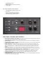
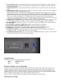
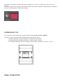
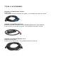
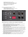
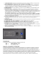
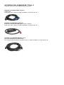
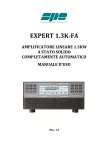
TTS26-A
HIGH OUTPUT ACTIVE SUBWOOFER
“HIGH OUTPUT AT PREMIUM SOUND QUALITY”
We started the design of our TT+ speakers with a clear idea in mind: maximum
high quality audio SPL in the smallest weight and size. Thanks to our state of the
art neodymium transducers, premium quality analog processing and powerful
class D amplifiers we reached and surpassed our original goals.
IMPORTANT NOTES
Before connecting and using the amplifier, please read this instruction manual carefully and keep it on
hand for future reference. The manual is to be considered an integral part of the product and must
accompany the amplifier when it changes ownership as a reference for correct installation and use as
well as for the safety precautions. RCF Spa. will not assume any responsibility for the incorrect
installation and/or use of the product.IANO
WARNING: To prevent the risk of fire or electric shock, never expose this equipment to rain or humidity.
SAFETY PRECAUTIONS
1. All the precautions, in particular the safety ones, must be read with special attention, as they provide
important information.
2. The power supply voltage of this equipment is sufficiently high to involve a risk of electrocution;
therefore, never install or connect the product with the power supply switched on.
3. Before powering up the amplifier, make sure that all the connections have been made correctly and
that the voltage of your power mains corresponds to the voltage shown on the rating plate on the unit; if
it does not, please contact your RCF dealer.
4. The metallic parts of the unit are earthed by means of the power cable. In the event that the current
outlet used for power does not provide the earth connection, contact a qualified electrician to earth the
equipment using the dedicated terminal.
5. To protect the power cable from damage, make sure that it is positioned so that it cannot be stepped
on or crushed by objects.
6. To prevent the risk of electric shock, never open the amplifier. There are no parts on the inside that
the user needs to access.
7. Make sure that no objects or liquids can get into the amplifier, as this may cause a short circuit.
8. Never attempt to carry out any operations, modifications, or repairs that are not expressly described
in this manual.
Contact your authorized service centre or qualified personnel should any of the following occur:
- the amplifier does not function (or functions in an anomalous way);
- the power supply cable has been damaged;
- objects or liquids have got into the unit;
- the amplifier has been subject to heavy impact.
9. When the amplifier is not to be used for long periods of time, switch it off and disconnect the power
cable.
10. If the amplifier begins to emit any strange odours or smoke, switch it off immediately and
disconnect the power supply cable.
11. Do not connect this product to any equipment or accessories not specified.
For suspended installation, only use the dedicated anchoring points and do not try to hang this product
using HANDLES or elements that are unsuitable or not specific for this purpose.
Also check the suitability of the support surface to which the product is anchored (wall, ceiling,
structure, etc.), and the components used for attachment (screw anchors, screws, brackets not supplied
by RCF etc.), which must guarantee the security of the system/installation over time, also considering,
for example, the mechanical vibrations normally generated by the transducer.
To prevent the risk of falling equipment, do not stack multiple units of this product unless this
possibility is specified in the instruction manual.
12. RCF Spa. strongly recommends this product is installed by professional qualified installers (or
specialised firms) who can ensure correct installation and certify it according to the regulations in force.
The entire audio system must comply with the current standards and regulations regarding electrical systems.
13. Supports and trolleys
The equipment should only be used on trolleys or supports, where necessary, that are recommended by
the manufacturer. The equipment/support/trolley assembly must be moved with extreme caution.
Sudden stops, excessive pushing force and uneven floors may cause the assembly to overturn.
14. There are numerous mechanical and electrical factors to be considered when installing a
professional audio system (in addition to those which are strictly acoustic, such as sound pressure,
angles of coverage, frequency response, etc.).
15. Hearing loss
Exposure to high sound levels can cause permanent hearing loss. The acoustic pressure level that leads
to hearing loss is different from person to person and depends on the duration of exposure. To prevent
potentially dangerous exposure to high levels of acoustic pressure, anyone who is exposed to these
levels should use adequate protection devices. When a transducer capable of producing high sound
levels is being used, it is therefore necessary to wear ear plugs or protective earphones.
See the technical specifications in the instruction manual for the maximum sound pressure the
loudspeaker is capable of producing
IMPORTANT NOTES
To prevent the occurrence of noise on the cables that carry microphone signals or line signals (for
example, 0 dB), only use screened cables and avoid running them in the vicinity of:
- equipment that produces high-intensity electromagnetic fields (for example, high power
transformers);
- mains cables;
- lines that supply loudspeakers.
OPERATING PRECAUTIONS
- Do not obstruct the ventilation grilles of the unit. Situate this product far from any heat sources
and always ensure adequate air circulation around the ventilation grilles.
- Do not overload this product for extended periods of time.
- Never force the control elements (keys, knobs, etc. ).
- Do not use solvents, alcohol, benzene or other volatile substances for cleaning the external parts of this
product.
TT+ HIGH DEFINITION TOURING AND THEATRE
RCF TT+ represents another prominent chapter in the long history of RCF Sound Systems.
Whether a speaker system is designed for live sound or large concert situations as well as permanent
installed theatre sound applications, the paying customer now expects a level of audio fidelity and
intelligibility of such a standard unsurpassed by previous generations.
This requirement has fostered the need for Audio Professionals to be able to offer a range of speaker
systems combined with dedicated Processing and Amplification Technologies that are superior in
Acoustic Performance and Control Technology.
RCF TT+ offers ready to use solutions and tools in true active high definition speaker systems.
INNOVATION INTEGRATION INTENSITY
INNOVATION. Our research and engineering faculty can today offer innovative projects with finite
control of each detail, from the loudspeaker voice coil wire to the highly efficient extended dynamic
amplifier topology.
There are many different ingredients that go into creating quality products and systems. These include
computer aided simulation software to assist the understanding of transducer behaviour and amplifier
operation and the relationship of dynamics and transient response. RCF utilise over thirty state of the art
software packages to identify magnetic circuits, voice coil dynamics, suspension linearity, horn
dispersion simulation, crossover filters, amplifier thermal behaviour etc.
INTEGRATION. RCF is one of only a few loudspeaker manufacturers worldwide who have the ability to
completely design and manufactures transducers, speaker systems and amplification and control
electronics. Our 50 plus years heritage in Audio combined with our state of
the art research and development and manufacturing processes allows us to seamlessly integrate all the
ingredients to design and build TT+
INTENSITY. The design philosophy for the new TT+ series is based upon offering the sound engineer
solutions and tools that are ready to use. Key factors are the ability to sustain very high power with
highly efficient sound pressure levels. Intense sound levels are created with extremely high definition
and extended dynamic range. Modern construction materials result in mechanical weight ratios that are
light for practical flying and portability.
TTS26-A, HIGH OUTPUT SUBWOOFER
The TTS26-A is a high power, high output active subwoofer system that sets a new standard in the
touring and theatre sound reinforcement.
Each transducer has been specifically designed for the application. The woofer provides large excursion
and very light weight.
The TTS26-A two 15” woofers features:
- lightweight, high force, neodymium magnet assembly
- 100 mm diameter, 25 mm length, inside-outside copper voice coil
- silicon reinforced double spiders
- Kevlar fiber doped, water resistant treated cone
- complex ventilation system for minimum power compression
The TTS26-A input section provides:
- In/Out XLR connectors
- Crossover Output XLR connector
- System sensitivity control (linear potentiometer) (-2 dBu ~ +10 dBu)
- Crossover set-up (90 Hz – 150 Hz)
- Low frequencies high pass set-up (30 Hz - 45 Hz)
- Delay set-up rotary switch
-
Cardioid set-up switch
By-pass switch
RDNet input output Ethercon connectors
4 status LEDs
The TTS26-A amplifier section features:
-
3400 Watt Digital amplifier modules with
PFC circuit
System cooling speed controlled fans
Powercon AC input- output connectors
Vibrostop floating aluminum panel
REAR PANEL FEATURES AND CONTROLS
1
2
3
4
5
6
7
8
9
MAIN SIGNAL XLR INPUT (BAL/UNBAL). The system accept female XLR input connectors and linelevel signals from a mixing console or other signal source.
SIGNAL LINK XLR OUTPUT. The output XLR male connector provides a loop trough for speakers
daisy chaining.
XOVER SIGNAL OUTPUT. The output XLR male connector provides a crossover high passed signal
(24 dB/octave) for satellites speakers.
INPUT SENSITIVITY. Controls the overall signal level at the input to the power amplifier. The
control ranges from + 10 dBu (maximum attenuation) to the –2 dBu sensitivity (maximum input
gain). The centre detent is +4 dBu (nominal level required to drive the amplifier at maximum
power).
XLOW CUT 30/45 Hz. This switch provides an high pass 24 dB/octave filtering at 30 or 45 Hz.
This is really useful for indoor situations (no very low frequencies that can create resonant sound)
or when all the power shall be used in the 45 Hz – 150 Hz range.
XOVER 90/150 HZ. Provides 24 dB/octave low-pass filtering at 90 Hz if released, at 150 Hz if
pressed. The same crossover frequency in high-pass is available from XOVER OUTPUT XLR.
TIME DELAY ENCODER. This encoder provides a time delay setting expressed in meters.
TIME DELAY DISPLAY. Display the time delay setting.
POWER INDICATOR. Power on indicator. When the power cord is connected and the power switch
is turned on this indicator lights green.
10 STATUS INDICATOR. The status indicator blink orange if the main amplifier or power supply is in
faulty condition. If the status indicator lights orange, switch off the amplifier and call the closest
RCF SERVICE CENTRE.
11 SIGNAL INDICATOR. The signal indicator lights green if there is signal present on the main XLR
input.
12 LIMITER INDICATOR. The amplifier has a built in compressor/limiter circuit to prevent clipping of
the amplifiers or overdriving the transducers.
When the compressor is active the led is blinking yellow. When the soft clipping circuit is active
the LED blinks orange. It is okay if the limit LED blinks occasionally. If the LED blinks frequently or
lights continuously, turn down the signal level. The amplifier has a built in RMS limiter. If the RMS
limiter is active the LED lights red. The RMS limiter has the purpose to prevent damages the
transducers. The speaker shall never be used with the limit indicator red, continuously. Continuous
operation with the RMS protection active can cause damages to the speaker.
13 CARDIOID SET-UP SWITCH. This switch provides a special equalisation and delay setting to create
a cardioid pattern when the system is used in conjunction with two other TTS56-A modules.
14 BY PASS SWITCH. Pressing this switch it is possible to by-pass the RDNet user setting preloaded
on the module.
15 DATA INPUT ETHERCON CONNECTOR. RDNet Input CAT5 Ethercon connector.
16 DATA LINK ETHERCON CONNECTOR. RDNet Link CAT5 Ethercon connector.
17 LINK LED. This green led is on if the module is addressed from the RDNet controller
18 ACTIVE LED. This green led is blinking if the RDNet communication is active.
19 POWER MAIN SWITCH. The power switch turns the AC power ON and OFF. Make sure that the
sensitivity is set to + 10 dBu when you turn on the speaker.
20 AC POWERCON RECEPTACLE. RCF TT+ series uses a POWERCON locking 3-pole AC mains. Always
use the specific power cord provided in the package.
CONNECTIONS
The XLR connectors use the following AES standard:
PIN 1 =
GROUND (SHIELD)
PIN 2 =
HOT (+)
PIN 3 =
COLD (-)
BEFORE TURNING ON THE SPEAKER
At this point you can connect the power supply cable and the signal cable, but before turning on the
speaker make sure that the volume control is at the minimum level (even on the mixer output). It is
important that the mixer is already ON before turning on the speaker. This will avoid damage to the
speakers and noisy “bumps” due to turning on parts on the audio chain. It is a good practice to always
turn on speakers at last and turn them off immediately after the show.
Now you can turn ON the speaker and adjust the volume control to a proper level.
TIME DELAY SETTING
The delay is expressed in meters. The delay resolution is 0.1 up to 10 meters and 1 from 10 to 20
meters.
To set the system time delay push the delay encoder and rotate it until the wanted setting is displayed.
Push the encoder again to confirm the setting.
CARDIOID SET-UP
It is possible to create subwoofer cardioid systems using groups of three modules.
A group is made of three modules, the group shall be made as follow:
- 2 modules pointing in forward direction, cardioid switch released
- 1 module pointing in backward direction, cardioid switch pressed
- all 3 modules shall have the same settings (system delay, sensitivity, x-low cut, x-over,…).
RDNet CONNECTION
The system is equipped with an RDNet connection on board. Using an RDNet controller unit it is possible
to:
- receive status information from the system ( amplifiers status, signal levels, system settings,…)
- send commands to the system (mute, solo, change sensitivity, change setting, set user eq, … )
See the RDNet user manual for details.
RDNet BY-PASS SWITCH
When the RDNet is present and the RDNet LINK LED is green the controller takes control over the module
independently of the BY-PASS SWITCH position
When the RDNet is not present, the BY-PASS switch act as follow:
-
BY-PASS SWITCH pressed (LED ON):
The system bypass the input board and reads the
RDNet user settings (last configuration saved).
-
BY-PASS SWITCH released (LED OFF): The system reads the input board and bypass the user
setting eventually loaded ion the speaker (last configuration eventually saved).
TTS26-A DEFAULT CONFIGURATION
The TTS26-A factory default configuration (the configuration that the system reads if the BY-PASS
switch is pressed) is the following:
Sensitivity
High pass
Low pass
Cardioid
Delay Bypass
User filters
+4 dBu
30 Hz
150 Hz
OFF
0
OFF
ALL FLAT
If the user set with RDNet a new configuration, the new configuration will be recalled when the BY-PASS switch is
pressed.
BY-PASS SWITCH
RDNet
BY-PASS LED
FUNCTION
ON
OFF
ON
OFF
ON
ON
OFF
OFF
ON
OFF
ON
OFF
Reads RDNet settings
Reads RDNet settings
Reads last saved used configuration
Reads input panel
TRANSPORTATION
The subwoofer system is equipped with 4 x 100 mm blue rubber wheels on the back of the cabinet for
transportation
Two aluminium die cast handles with rubber hand-grip are available on each side of the speaker system.
The outdoor quality, Baltic birch plywood, cabinet is protected with heavy duty, scratch resistant, polyurea coating.
INSTALLATION
The TTS26-A active subwoofer features:
-
top pole mount cap for professional 35 mm speaker pole mount
top plates to assembly a TTL11-A system on top of a TTS26-A subwoofer
WARNING: Never suspend TT+ speakers by there handles. Handles are intended for transportation, not
for rigging.
WARNING: Always make sure that the maximum current requirement does not exceed the maximum
admitted POWERCON current. In case of doubt call the closest RCF SERVICE CENTRE.
MAINS SUPPLY
The system accept mains supply voltage115-230 (+15/-15%) V ~
TTS26-A
FUSE F1
FUSE F2
FUSE F3
VALUE F15 AL 250 V ~
VALUE T 10 AL 250 V ~
VALUE T 10 AL 250 V ~
TTS26-A ACCESSORIES
13360138 AC POWER CABLE 6XTTL55
POWER CABLE
1 piece for EVERY 6 pieces OF TTS26 SUB are suggested. – Full compatibility with Socapex SL 419 Series
13360145 AC POWER BOX 6XTTL55
EUROPEAN STAGE BOX TO POWER 6 TTL55-A LINE ARRAY MODULES OR 6 TTS56-A MODULES
1 piece for 6 pieces OF TTS26 SUB are suggested. – Full compatibility with Socapex SL 419 Series
13360146 AC POWER EXTENSION TTL55
POWER EXTENSION CABLE
20 meters AC power extension cable – Full compatibility with Socapex SL 419 Series
IMPORTANTE. Prima di collegare ed utilizzare questo prodotto, leggere attentamente le istruzioni
contenute in questo manuale, il quale è da conservare per riferimenti futuri. Il presente manuale
costituisce parte integrante del prodotto e deve accompagnare quest’ultimo anche nei passaggi di
proprietà, per permettere al nuovo proprietario di conoscere le modalità d’installazione e d’utilizzo e le
avvertenze per la sicurezza. L’installazione e l’utilizzo errati del prodotto esimono la RCF S.p.A. da ogni
responsabilità.
ATTENZIONE: Per prevenire i rischi di fiamme o scosse elettriche, non esporre mai questo prodotto alla
pioggia o all'umidità (salvo il caso in cui sia stato espressamente progettato e costruito per l’uso
all’aperto).
AVVERTENZE PER LA SICUREZZA
1. Tutte le avvertenze, in particolare quelle relative alla sicurezza, devono essere lette con particolare
attenzione, in quanto contengono importanti informazioni.
2. ALIMENTAZIONE DA RETE. La tensione di alimentazione dell’apparecchio ha un valore
sufficientemente alto da costituire un rischio di folgorazione per le persone: non procedere mai
all’installazione o connessione dell’apparecchio con l’alimentazione inserita.
Prima di alimentare questo prodotto, assicurarsi che tutte le connessioni siano corrette e che la tensione
della vostra rete di alimentazione corrisponda quella di targa dell’apparecchio, in caso contrario
rivolgetevi ad un rivenditore RCF.
Le parti metalliche dell’apparecchio sono collegate a terra tramite il cavo di alimentazione. Nel caso la
presa di corrente utilizzata per l’alimentazione non fornisca il collegamento con la terra, contattare un
elettricista qualificato, che provvederà a connettere a terra l’apparecchio tramite l’apposito morsetto.
Accertarsi che il cavo di alimentazione dell’apparecchio non possa essere calpestato o schiacciato da
oggetti, al fine di salvaguardarne la perfetta integrità. Per evitare il rischio di shock elettrici, non aprire
mai l’apparecchio: all’interno non vi sono parti che possono essere utilizzate dall’utente.
3. Impedire che oggetti o liquidi entrino all’interno del prodotto, perché potrebbero causare un corto
circuito.
4. Non eseguire sul prodotto interventi / modifiche / riparazioni se non quelle espressamente descritte
sul manuale istruzioni.
Contattare centri di assistenza autorizzati o personale altamente qualificato quando:
- l’apparecchio non funziona (o funziona in modo anomalo);
- il cavo di alimentazione ha subito gravi danni;
- oggetti o liquidi sono entrati nell’apparecchio;
- l’apparecchio ha subito forti urti.
5. Qualora questo prodotto non sia utilizzato per lunghi periodi, togliere la tensione dal cavo di
alimentazione (o scollegare l’alimentatore esterno).
6. Nel caso che dal prodotto provengano odori anomali o fumo, spegnerlo immediatamente e togliere la
tensione dal cavo di alimentazione (o scollegare l’alimentatore esterno).
7. Non collegare al prodotto altri apparecchi e accessori non previsti. Quando è prevista l’installazione
sospesa, utilizzare solamente gli appositi punti di ancoraggio e non cercare di appendere questo
prodotto tramite elementi non idonei o previsti allo scopo.
Verificare inoltre l’idoneità del supporto (parete, soffitto, struttura ecc., al quale è ancorato il prodotto) e
dei componenti utilizzati per il fissaggio (tasselli, viti, staffe non fornite da RCF ecc.) che devono
garantire la sicurezza dell’impianto / installazione nel tempo, anche considerando, ad esempio,
vibrazioni meccaniche normalmente generate da un trasduttore.Per evitare il pericolo di cadute, non
sovrapporre fra loro più unità di questo prodotto, quando questa possibilità non è espressamente
contemplata dal manuale istruzioni.
8. La RCF S.p.A. raccomanda vivamente che l’installazione di questo prodotto sia eseguita solamente da
installatori professionali qualificati (oppure da ditte specializzate) in grado di farla correttamente e
certificarla in accordo con le normative vigenti.
Tutto il sistema audio dovrà essere in conformità con le norme e le leggi vigenti in materia di impianti elettrici.
9. Sostegni e Carrelli. Se previsto, il prodotto va utilizzato solo su carrelli o sostegni consigliati dal
produttore. L’insieme apparecchio-sostegno / carrello va mosso con estrema cura. Arresti improvvisi,
spinte eccessive e superfici irregolari o inclinate possono provocare il ribaltamento dell’assieme.
10. Vi sono numerosi fattori meccanici ed elettrici da considerare quando si installa un sistema audio
professionale (oltre a quelli prettamente acustici, come la pressione sonora, gli angoli di copertura, la
risposta in frequenza, ecc.).
11. PERDITA DELL’UDITO. L’esposizione ad elevati livelli sonori può provocare la perdita permanente
dell’udito. Il livello di pressione acustica pericolosa per l’udito varia sensibilmente da persona a persona
e dipende dalla durata dell’esposizione. Per evitare un’esposizione potenzialmente pericolosa ad elevati
livelli di pressione acustica, è necessario che chiunque sia sottoposto a tali livelli utilizzi delle adeguate
protezioni; quando si fa funzionare un trasduttore in grado di produrre elevati livelli sonori è necessario
indossare dei tappi per orecchie o delle cuffie protettive. Consultare i dati tecnici contenuti nel manuale
istruzioni per conoscere la massima pressione sonora che il diffusore acustico è in grado di produrre.
NOTE IMPORTANTI
Per evitare fenomeni di rumorosità indotta sui cavi che trasportano segnali dai microfoni o di linea (per
esempio 0dB), usare solo cavi schermati ed evitare di posarli nelle vicinanze di apparecchiature che
producono campi elettromagnetici di forte intensità (per esempio trasformatori di grande di potenza),
cavi di rete, linee che alimentano altoparlanti.
PRECAUZIONI D’USO
- Non ostruire le griglie di ventilazione dell'unità. Collocare il prodotto lontano da fonti di calore e
garantire la circolazione dell’aria in corrispondenza delle griglie di aerazione.
- Non sovraccaricare questo prodotto per lunghi periodi.
- Non forzare mai gli organi di comando (tasti, manopole ecc.).
- Non usare solventi, alcool, benzina o altre sostanze volatili per la pulitura delle parti esterne
dell'unità.
TT+ HIGH DEFINITION TOURING AND THEATRE
RCF TT+ rappresenta un altro importante capitolo della lunga storia di RCF.
Sia che i diffusori siano progettati per musica dal vivo, per concerti in grandi spazi o per l’installazione
fissa in teatri, il cliente si aspetta un livello di fedeltà e di intelligibilità decisamente superiore a quella
degli impianti di precedente generazione.
Questa esigenza ha fatto si che i professionisti del settore audio sentissero la necessità di offrire
un’ampia gamma di diffusori acustici abbinata a tecnologie di elaborazione ed amplificazione con
prestazioni acustiche e di controllo di qualità superiore.
RCF TT+ offre soluzioni e strumenti di immediato utilizzo nel campo dei diffusori attivi ad alta
definizione.
INNOVAZIONE, INTEGRAZIONE, INTENSITÀ
INNOVAZIONE – Il nostro team di ricerca e sviluppo è in grado di offrire progetti innovativi con controllo
di ogni dettaglio, dal rame smaltato di avvolgimento della bobina dell’altoparlante fino alla topologia ad
elevata efficienza dell’amplificatore a dinamica estesa.
Sono molti gli ingredienti che contribuiscono a creare prodotti e sistemi di qualità, tra questi i software
di simulazione computerizzata che aiutano a comprendere il comportamento dei trasduttori ed il
funzionamento dell’amplificatore, oltre allo studio della risposta dinamica e della risposta ai transienti.
RCF utilizza oltre trenta software per lo studio di circuiti magnetici, dinamica delle bobine, linearità delle
sospensioni, simulazione della dispersione delle trombe, filtri crossover, comportamento termico
dell’amplificatore, ecc.
INTEGRAZIONE - RCF è uno dei pochi produttori di altoparlanti al mondo in grado di elaborare
completamente i progetti e di costruire trasduttori, diffusori, elettronica d’amplificazione e controllo. La
nostra esperienza di oltre 50 anni nel settore audio abbinata ai nostri avanzati processi di ricerca e
sviluppo nonché di produzione, ci permette di integrare perfettamente tutti gli ingredienti che
compongono il sistema TT+.
INTENSITÀ– La filosofia progettuale della nuova serie TT+, si basa sulla volontà di offrire soluzioni
tecniche e strumenti acustici di
immediato utilizzo. Fattori chiave sono la capacità di sostenere elevati livelli di potenza e di pressione
sonora con grande efficienza. Intensi livelli sonori sono riprodotti con una definizione estremamente
elevata ed estesa dinamica. I materiali high tech con i quali è costruita la serie TT+ permettono di
ottenere un peso complessivo molto basso facilitando quindi sospensione e trasporto.
ALTI LIVELLI E GRANDE QUALITÀ ACUSTICA
Abbiamo avviato la progettazione dei diffusori compatti della serie TT+ con un’idea chiara in mente: la
massima pressione sonora con elevatissima qualità audio, il minor peso e le più piccole dimensioni.
Con i nostri avanzatissimi trasduttori al neodimio, l’elaborazione analogica d’eccellente qualità ed i
potenti amplificatori in classe D abbiamo raggiunto e superato i nostri obiettivi iniziali.
Il TTS26-A è un subwoofer attivo professionale ad alta potenza che definisce un nuovo standard nel
rinforzo sonoro touring.
I trasduttori sono stati progettati in modo specifico per l’applicazione, sono dotati di elevata escursione
e pesi estremamente contenuti.
I woofer del sistema TTS26-A hanno le seguenti caratteristiche:
- Circuito magnetico in neodimio, ad alta energia e dal peso contenuto
- Bobina in rame, interno-esterno di 100 mm di diametro e 25 mm di lunghezza
- Sospensioni doppie al silicone
- Cono caricato con fibre di kevlar e trattamento resistente all’acqua
- Doppio sistema di ventilazione per garantire la minima compressione acustica alla massima
potenza
La sezione ingressi è dotata di:
- Connettori In/Out XLR
- Connettore XLR Crossover Out
- Potenziometro lineare per variare la sensibilità (-2 dBu - +10 dBu)
-
Selezione del crossover (90 Hz – 150 Hz)
Selezione del filtro passa alto (30 Hz - 45 Hz)
Selettore rotativo per l’assegnazione del ritardo temporale
Selettore per la selezione della configurazione cardioide
Selettore di by-pass delle impostazioni RDNet
Connettori di ingresso ed uscita RDNet
4 LED di stato
La sezione di amplificazione del TTS26-A è dotata di:
- amplificatore digitale da 3400 Watt
- circuito di alimentazione dotato di circuito di correzione PFC
- connettore di alimentazione in/out Powercon
- meccanica in alluminio sospesa con Vibrostop
CARATTERISTICHE E CONTROLLI DEL PANNELLO POSTERIORE
1
2
3
4
5
6
7
8
INGRESSO XLR SEGNALE AUDIO (BAL/UNBAL). Il sistema accetta connettori di ingresso XLR
femmina e segnali a livello linea da mixer o da alter sorgenti di segnale.
USCITA XLR SEGNALE AUDIO . L’uscita XLR maschio provvede una connessione in uscita del
segnale audio per connettere più diffusori allo stesso segnale.
USCITA XOVER SEGNALE AUDIO. Il connettore XLR maschio fornisce un uscita audio passa-alto
(24 dB/ottava) per diffusori satellite.
SENSIBILITA’ IN INGRESSO. Controlla il livello del segnale in ingresso all’amplificatore di potenza.
Il controllo varia da +10 dBu (massima attenuazione) alla sensibilità –2 dBu (massimo guadagno in
ingresso). La sensibilità nella posizione centrale è +4 dBu (livello nominale richiesto per ottenere
la massima potenza dagli amplificatori).
XLOW CUT. Questo pulsante fornisce al sistema un filtro passa alto (24 dB/ottava a 45 hertz). Può
essere molto utile per situazioni indoor, dove le frequenze molto basse possono provocare onde
stazionarie e perdita di intelligibilità del sistema. Può essere usato anche quando si vuol
concentrare tutta la potenza dell’amplificatore nella banda 45 Hz – 150Hz.
XOVER 90/150 HZ. Questo pulsante fornisce una frequenza di crossover ad 90 Hz se rilasciato, a
150 Hz se premuto. La stessa frequenza di crossover è disponibile per il satellite all’uscita di
segnale audio XOVER OUTPUT XLR.
ENCODER RITARDO TEMPORALE. Permette l’impostazione del ritardo temporale in metri.
DISPLAY RITARDO TEMPORALE. Indica il ritardo settato sul modulo espresso in metri.
9
10
11
12
13
14
15
16
17
18
19
20
POWER INDICATOR. Indicazione di alimentazione presente. Quando il diffusore è connesso alla
rete e l’interruttore in posizione ON il led si accende con colore VERDE.
STATUS INDICATOR. L’indicatore di stato si accende con colore ARANCIONE se l’amplificatore
principale evidenzia un malfunzionamento. Nel caso in cui il led STATUS si accenda spegnere e
scollegare l’apparecchio e rivolgersi al CENTRO ASSISTENZA RCF più vicino.
SIGNAL INDICATOR. Il led di segnale si accende con colore VERDE se è presente segnale audio
all’ingresso XLR.
LIMIT INDICATOR. L’amplificatore è dotato di un circuito di compressore/limiter in modo da
prevenire il clipping dell’amplificatore o di sovrapilotare gli altoparlanti. Quando il circuito di
compressione è attivo il LED lampeggia con colore giallo. Quando il circuito di soft clipping è attivo
il LED lampeggia con colore ARANCIONE. E’ accettabile che il LED lampeggi occasionalmente. Se il
LED lampeggia frequentemente o si accende di continuo ridurre il segnale in ingresso.
L’amplificatore è dotato di un circuito di limiter RMS. Il limiter RMS serve a proteggere i trasduttori.
Se il circuito di protezione RMS è attivo il LED si accende con colore ROSSO. Il diffusore non deve
mai essere utilizzato con il LED ROSSO acceso in modo continuo, operare a lungo con il led rosso
acceso può causare danni al diffusore.
PULSANTE CARDIOID SET-UP. Questo pulsante, una volta premuto, attiva una equalizzazione ed
un ritardo temporale del modulo atti a creare un sistema cardioide utilizzando gruppi di 3
subwoofers.
PULSANTE BY PASS. Premendo questo pulsante è possibile by-passare le impostazioni utente precaricate sul modulo.
CONNETTORE DATA INPUT ETHERCON. Connettore RDNet Input CAT5 Ethercon.
CONNETTORE DATA LINK ETHERCON. Connettore RDNet Link CAT5 Ethercon.
LINK LED. Questo LED si illumina verde quando il modulo è indirizzato da un controller RDNet.
ACTIVE LED. Questo LED lampeggia verde quando la comunicazione RDNet è attiva.
INTERRUTTORE DI ALIMENTAZIONE. L’ interruttore apre e chiude l’alimentazione in corrente AC.
Assicurarsi che la sensibilità sia +10 dBu quando si accende il diffusore.
PRESA AC POWERCON. La serie RCF TT+ utilizza connettori AC POWERCON . Utilizzare sempre i
cavi rete forniti a corredo
CONNESSIONI
Il connettore di ingresso XLR segue il seguente standard AES:
PIN 1 =
TERRA (GROUND ; SHIELD)
PIN 2 =
LATO CALDO (HOT ; +)
PIN 3 =
LATO FREDDO (COLD ; -)
PRIMA DI ACCENDERE IL DIFFUSORE
A questo punto potete inserire il connettore di alimentazione e il connettore di segnale, ma prima di
accendere il diffusore assicuratevi che il controllo di volume sia al minimo sia sul diffusore che sulla
sorgente sonora collegata al diffusore (che generalmente sarà un mixer); è importante anche che il
mixer sia già acceso al momento in cui viene acceso il diffusore a lui collegato. Queste due precauzioni
vi eviteranno innanzitutto di accendere i diffusori in presenza di forti segnali in ingresso (evitando di
causare danni al diffusore stesso ma soprattutto alle persone che vi si possono trovare davanti) e inoltre
di far arrivare agli altoparlanti e al pubblico i fastidiosi “bump” causati dall’accensione delle
apparecchiature audio a monte dei diffusori. Infatti è buona regola che i diffusori amplificati e gli
amplificatori in genere siano sempre le ultime apparecchiature ad essere accese dopo il montaggio e le
prime ad essere spente alla fine dello spettacolo.
A questo punto potete accendere il diffusore e alzare il controllo di livello a seconda delle necessità.
IMPOSTAZIONE DEL RITARDO TEMPORALE (TIME DELAY)
Il ritardo è espresso in metri. Le risoluzione del ritardo è di 0.1 fino a 10 metri ed 1 da 10 a 20 metri.
Per impostare il ritardo premere l’encoder e successivamente ruotarlo sino a raggiungere il ritardo
desiderato.
Premere nuovamente l’encoder per confermare l’impostazione.
IMPOSTAZIONE DELLA FUNZIONE CARDIOIDE (CARDIOID)
E’ possibile creare sistemi cardioide utilizzando gruppi di subwoofers.
Un gruppo è costituito di tre moduli disposti come segue:
- 2 moduli rivolti nella direzione di propagazione, pulsante cardioid rilasciato
- 1 modulo rivolto nella direzione opposta alla propagazione, pulsante cardioid inserito
- tutti i 3 moduli devono avere le medesime impostazioni generali (ritardo, sensibilità, xover,…)
CONNESSIONE RDNet
Il sistema è dotato di connessione RDNet. Utilizzando un controller RDNet è possibile:
- ricevere informazioni di stato del sistema (stato degli amplificatori, dei segnali, delle
impostazioni,…)
- inviare comandi al sistema (mute, solo, variazioni di livello, di impostazioni,…)
Riferirsi al manuale utente RDNet per maggiori dettagli.
PULSANTE RDNet BY-PASS
Quando RDNet è presente ed il LED RDNet LINK è verde il controller ha il controllo del modulo e dei
sui ingressi indipendentemente dalla posizione del tasto.
Quando RDNet non è presente, il tasto BY-PASS agisce come segue:
-
TASTO BY-PASS premuto (LED ON):
Il sistema by-passa la scheda ingressi e legge la
configurazione utente impostata da RDNet (ultima configurazione salvata).
-
TASTO BY-PASS rilasciato (LED OFF): Il sistema legge la scheda ingressi e bypassa lea
configurazione utente eventualmente caricata sul modulo (ultima configurazione eventualmente
salvata).
CONFIGURAZIONE DI DEFAULT TTS26-A
La configurazione di default del modulo TTS56-A (la configurazione che viene letta se RDNet non è
presente ed il pulsante by-pass è premuto) è la seguente:
Sensitivity
High pass
Low pass
Cardioid
Delay Bypass
User filters
Sensibilità
Passa alto
Passa basso
Cardioide
Ritardo
By-pass
Filtri utente
+4 dBu
30 Hz
150 Hz
OFF
0
OFF
ALL FLAT
Nel caso in cui l’utente setti tramite RDNet una nuova configurazione, la nuova configurazione verrà richiamata
quando il tasto BY-PASS è premuto.
BY-PASS SWITCH
RDNet
BY-PASS LED
FUNCTION
ON
OFF
ON
OFF
ON
ON
OFF
OFF
ON
OFF
ON
OFF
Reads RDNet settings
Reads RDNet settings
Reads last saved used configuration
Reads input panel
TRASPORTO
Il subwoofer è dotato di 4 ruote in gomma per il trasporto di diametro 100 mm posizionate sul lato posteriore del
diffusore.
Sono disponibili su ogni lato del diffusore 2 maniglie pressofuse in alluminio con impugnatura in gomma.
Il mobile, realizzato in multistrato di betulla per uso da esterno, è rivestito da una robusta protezione antigraffio in
polyurea.
INSTALLAZIONE DEL DIFFUSORE
Il subwoofer attivo TTS26-A presenta:
-
Inserto a tazza per asta professionale in acciaio da 35 mm
Piastre per l’installazione di un sistema TTL11-A sopra ad un sub TTS26-A
ATTENZIONE: Non sospendere mai il diffusore per mezzo delle maniglie. Le maniglie sono state
progettate per il trasporto del diffusore, non per la sua sospensione.
ATTENZIONE: Assicurarsi sempre che la richiesta massima di corrente non superi la corrente massima
ammessa dai connettori POWERCON. In caso di dubbio contattare il CENTRO ASSISTENZA RCF più vicino.
TENSIONE DI ALIMENTAZIONE
Il sistema accetta una tensione di alimentazione di 115-230 (+15/-15%) V ~
TTS26-A
FUSIBILE F1
FUSIBILE F2
VALORE VALORE F15 AL 250 V ~
T 10 AL 250 V ~
FUSIBILE F3
VALORE
T 10 AL 250 V ~
ACCESSORI DEL SUBWOOFER TTS56-A
I seguenti accessori sono separatamente disponibili:
13360138 AC POWER CABLE 6XTTL55
POWER CABLE
1pezzo ogni 6 moduli di TTS26-A. Completa compatibilità con Socapex Serie SL 419.
13360145 AC POWER BOX 6XTTL55
STAGE BOX EUROPEO PER ALIMENTARE 6 TTL55-A O 6 TTS56-A
1pezzo ogni 6 moduli di TTS26-A. Completa compatibilità con Socapex Serie SL 419.
13360146 AC POWER EXTENSION TTL55
CAVO DI ESTENSIONE DELL’ALIMENTAZIONE
Cavo di estensione dell’alimentazione di lunghezza 20 metri – Completa compatibilità con Socapex Serie SL 419.
TTS26-A TECHNICAL SPECIFICATIONS
ACOUSTICAL TT26-A Operating frequency range
Max SPL
Crossover point
35 – 120 Hz 140 dB
90 Hz/ 150 Hz
TRANSDUCERS
Low frequency
2 x 15” neodymium woofer, 4.0” voice coil
3400 Watt digital amplifier
PFC switching power supply
Sensitivity Control (-2 dBu ~ 10 dBu)
X-low cut, X-over selection
Delay set-up
Cardioid setting, RDNet bypass
User settings (RDNet)
AMPLIFIERS
CONNECTIONS
Signal Input/Output
Power Input/Output
RDNet Input/Output
XLR male/female
Powercon male/female
Cat5 Ethercon
CONTROLS
DSP Controls
DSP PROCESSING
High pass, low pass, equalisation
Crossover output processing
Fast limiter, dynamic compressor
RMS limiter
PHISICAL
Size Weight
Cabinet material
Hardware 460 x 900 x 700 mm
56 Kg
Baltic birch plywood
4 x die cast handles
TTL11-A mounting plates.