1
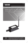
Black Box Tech Support: FREE! Live. 24/7. Tech support the way it should be. Great tech support is just 20 seconds away at 724-746-5500 or blackbox.com. About Black Box Black Box Network Services is your source for more than 118,000 networking and infrastructure products. You’ll find everything from cabinets and racks and power and surge protection products to media converters and Ethernet switches all supported by free, live 24/7 Tech support available in 20 seconds or less. © Copyright 2009. All rights reserved. 724-746-5500 | blackbox.com June 2009 LS900PKA LongSpan Integrated Radio and Directional Antenna Kit Industrial-grade, long-range wireless Ethernet. BLACK BOX Use this pair of integrated radios/antennas to transmit long-range wireless ® Ethernet signals. Customer Support Information Order toll-free in the U.S.: Call 877-877-BBOX (outside U.S. call 724-746-5500) • FREE technical support 24 hours a day, 7 days a week: Call 724-746-5500 or fax 724-746-0746 • Mailing address: Black Box Corporation, 1000 Park Drive, Lawrence, PA 15055-1018 • Web site: www.blackbox.com • E-mail: [email protected] FCC and NOM Statements FEDERAL COMMUNICATIONS COMMISSION AND INDUSTRY CANADA RADIO FREQUENCY INTERFERENCE STATEMENTS This equipment generates, uses, and can radiate radio-frequency energy, and if not installed and used properly, that is, in strict accordance with the manufacturer’s instructions, may cause interference to radio communication. It has been tested and found to comply with the limits for a Class A computing device in accordance with the specifications in Subpart B of Part 15 of FCC rules, which are designed to provide reasonable protection against such interference when the equipment is operated in a commercial environment. Operation of this equipment in a residential area is likely to cause interference, in which case the user at his own expense will be required to take whatever measures may be necessary to correct the interference. Changes or modifications not expressly approved by the party responsible for compliance could void the user’s authority to operate the equipment. This digital apparatus does not exceed the Class A limits for radio noise emission from digital apparatus set out in the Radio Interference Regulation of Industry Canada. Le présent appareil numérique n’émet pas de bruits radioélectriques dépassant les limites applicables aux appareils numériques de la classe A prescrites dans le Règlement sur le brouillage radioélectrique publié par Industrie Canada. Normas Oficiales Mexicanas (NOM) Electrical Safety Statement INSTRUCCIONES DE SEGURIDAD 1. Todas las instrucciones de seguridad y operación deberán ser leídas antes de que el aparato eléctrico sea operado. 2. Las instrucciones de seguridad y operación deberán ser guardadas para referencia futura. 3. Todas las advertencias en el aparato eléctrico y en sus instrucciones de operación deben ser respetadas. 4. Todas las instrucciones de operación y uso deben ser seguidas. 724-746-5500 | blackbox.com Page 1 LongSpan 900-MHz Integrated Radio and Directional Antenna Kit 5. El aparato eléctrico no deberá ser usado cerca del agua—por ejemplo, cerca de la tina de baño, lavabo, sótano mojado o cerca de una alberca, etc.. 6. El aparato eléctrico debe ser usado únicamente con carritos o pedestales que sean recomendados por el fabricante. 7. El aparato eléctrico debe ser montado a la pared o al techo sólo como sea recomendado por el fabricante. 8. Servicio—El usuario no debe intentar dar servicio al equipo eléctrico más allá lo descrito en las instrucciones de operación. Todo otro servicio deberá ser referido a personal de servicio calificado. 9. El aparato eléctrico debe ser situado de tal manera que su posición no interfiera su uso. La colocación del aparato eléctrico sobre una cama, sofá, alfombra o superficie similar puede bloquea la ventilación, no se debe colocar en libreros o gabinetes que impidan el flujo de aire por los orificios de ventilación. 10. El equipo eléctrico deber ser situado fuera del alcance de fuentes de calor como radiadores, registros de calor, estufas u otros aparatos (incluyendo amplificadores) que producen calor. 11. El aparato eléctrico deberá ser connectado a una fuente de poder sólo del tipo descrito en el instructivo de operación, o como se indique en el aparato. 12. Precaución debe ser tomada de tal manera que la tierra fisica y la polarización del equipo no sea eliminada. 13. Los cables de la fuente de poder deben ser guiados de tal manera que no sean pisados ni pellizcados por objetos colocados sobre o contra ellos, poniendo particular atención a los contactos y receptáculos donde salen del aparato. 14. El equipo eléctrico debe ser limpiado únicamente de acuerdo a las recomendaciones del fabricante. 15. En caso de existir, una antena externa deberá ser localizada lejos de las lineas de energia. 16. El cable de corriente deberá ser desconectado del cuando el equipo no sea usado por un largo periodo de tiempo. Page 2 724-746-5500 | blackbox.com NOM Statement 17. Cuidado debe ser tomado de tal manera que objectos liquidos no sean derramados sobre la cubierta u orificios de ventilación. 18. Servicio por personal calificado deberá ser provisto cuando: A: El cable de poder o el contacto ha sido dañado; u B: Objectos han caído o líquido ha sido derramado dentro del aparato; o C: El aparato ha sido expuesto a la lluvia; o D: El aparato parece no operar normalmente o muestra un cambio en su desempeño; o E: El aparato ha sido tirado o su cubierta ha sido dañada. 724-746-5500 | blackbox.com Page 3 LongSpan 900-MHz Integrated Radio and Directional Antenna Kit TRADEMARKS USED IN THIS MANUAL Black Box and the Double Diamond logo are registered trademarks of BB Technologies, Inc. Mac is a registered trademark of Apple Computer, Inc. Linux is a registered trademark of Linus Torvalds. Microsoft and Windows are registered trademarks of Microsoft Corporation. Any other trademarks mentioned in this manual are acknowledged to be the property of the trademark owners. Page 4 724-746-5500 | blackbox.com Table of Contents Table of Contents Chapter Page 1. Specifications....................................................................................................6 2. Overview..........................................................................................................7 2.1 Introduction..............................................................................................7 2.2 Front View................................................................................................8 2.3 Back View.................................................................................................8 2.4 What’s Included........................................................................................9 3. Installation......................................................................................................10 3.1 Digital Setup...........................................................................................10 3.2 Physical Setup.........................................................................................15 4. 900-MHz Channels........................................................................................16 A. Troubleshooting.............................................................................................. 17 A.1 Calling Black Box....................................................................................17 A.2 Shipping and Packaging.........................................................................17 724-746-5500 | blackbox.com Page 5 LongSpan 900-MHz Integrated Radio and Directional Antenna Kit 1. Specifications Distance: 40 miles line of sight with 15-dBi antenna Environmental: Operating temperature: -40 to +158° F (-40 to 70° C) Radio Channels/Bandwidth: 12 non-overlapping with 2.0833-MHz spacing and 1.75-MHz occupied bandwidth Radio Link Budget: 148 dB with 15 dBi antenna Receive Sensitivity: -97 dBm at 10e-4 BER (-112 dBm with -15 dBi antenna) Speed: RF Transmission Rate: 1.536 Mbps; Ethernet Throughput: 935 kbps Connectors: (1) RJ-45 PoE 10BASE-T/100BASE-TX Indicators: LEDs: (1) Power, (1) Ethernet Link, (1) RF RX, (1) RF TX, (4) Channel, (6) Link Power: From 110-VAC, 60 Hz external power adapter or PoE injector Size: Each radio: 2"H x 6.7"W x 3.1"D (5 x 17 x 8 cm) Page 6 724-746-5500 | blackbox.com Chapter 2: Overview 2. Overview 2.1 Introduction With the LongSpan 900-MHz Integrated Radio and Directional Antenna (2-Unit) Kit, Point-to-Point (LS900PKA), you can create a long-range, wireless Ethernet network with up to 16 subscriber units per access point (AP). The configuration may include any combination of LS900A (LongSpan 900-MHz Wireless Ethernet Indoor/ Outdoor Radio) or LS900PKA extenders. To configure a wireless link using LS900A or and/or LS900PKA radios, your system must meet the folllowing conditions: • Each radio must be configured as an access point (AP) or subscriber unit (SU). • Each radio must have an IP address that is unique among all others on the same network. • The AP must know how many SUs are expecting to communicate with it. • The AP and any given SU must agree on which radio-frequency channel they are using. The radios set this automatically. • You must assign the SU a unique subscriber ID to specify which time-division slot it will use when communicating with the AP. • The AP and any given SU must share a common 128-bit encryption key. APs can exchange keys with up to 63 SUs, though only 16 can be connected at any given time. The AP automatically scans for the best of 12 available radio frequency channels, encrypts Ethernet data received from the network, and transmits it wirelessly to the correct SU. The AP constantly monitors the radio link and automatically changes the channel if performance is degraded because of interference. If two AP units are very close to one another, they may interfere if operating on adjacent frequency channels. Place them at least 10 feet apart or manually select non-adjacent channels for their operation. Also, place the SU at least 10 feet from the AP to avoid overloading the receivers. You can connect any 10/100BASE-T Ethernet client device (ECD) to an Indoor/ Outdoor Radio subscriber unit (SU). Each SU encrypts Ethernet traffic it receives from the attached ECD and transmits the data wirelessly to its AP. You can plug each SU directly into an ECD without adding drivers or loading software. Once the AP/SU pair is configured and running, it behaves like a continuous Ethernet cable. 724-746-5500 | blackbox.com Page 7 LongSpan 900-MHz Integrated Radio and Directional Antenna Kit 2.2 Front View Figure 2-1 shows the front view of the LS900PKA. Figure 2-1. The LS900PKA’s front view. 2.3 Back View Figure 2-2 shows the back view of the LS900PKA. Figure 2-2. The LS900PKA‘s back view. Page 8 724-746-5500 | blackbox.com Chapter 2: Overview 2.4 What’s Included Your package should include the following items. If anything is missing or damaged, please contact Black Box at 724-746-5500. • (2) indoor/outdoor PoE radio w/integrated 12.5 db antenna housings • (2) housing labels (BBOX applied) • (2) PoE mid-span injector • (2) 12-V power supplies in box • (2) pole-mount brackets in box • This user’s manual • (1) cardboard box • (1) box sticker (BBOX applied) 724-746-5500 | blackbox.com Page 9 LongSpan 900-MHz Integrated Radio and Directional Antenna Kit 3. Installation 3.1 Digital Setup 1. The radio’s built-in browser interface enables you to configure it digitally. Power it on at least temporarily to a network containing a computer that can run a conventional web browser. 2. Download the Black Box Discovery Utility from our Web site: http://www.blackbox.com/go/LongSpan/LongSpan_Finder This link will prompt you to either Run or Save the application. Press Run to start it immediately; press Save to save the application before running. NOTE: This utility only runs on Microsoft® Windows®, not Linux® or Mac®. If you must use a non Windows computer for configuration, make sure your subnet mask allows your computer to see 192.168.1.17. Connect to that default IP address with your web browser, continuing the setup procedure with Step 6. 3. Run the IP Discovery Utility, ipfinder.exe and you should see a window similar to Figure 3-1. Figure 3-1. IP Discovery screen. Page 10 724-746-5500 | blackbox.com Chapter 3: Installation The LS900PKA should appear in the list as the default address of 192.168.1.17. If it does not, click “Search” to regenerate the list. If it still does not appear, you might either have a connection issue and need to re-examine the cabling or you might have a firewall issue on your computer. 4.Double-click the item in the list that refers to the radio being configured. You will see a second window similar to Figure 3-2. Figure 3-2. Radio IP Configuration screen. 724-746-5500 | blackbox.com Page 11 LongSpan 900-MHz Integrated Radio and Directional Antenna Kit The information on the left in Figure 3-2 is the current status of the radio; the boxes on the right allow you to change it. Choose your desired parameters and click “Apply.” 5.Write down the IP address and password you just chose, then click “Go to Device Web Page.” Your default Web browser will launch with the device IP address in the browser address bar. Or, you may launch the browser on your own and enter the Web page address manually: http://[the IP address you just set]. 6. The browser page that loads first shows the current device information and QoS statistics and provides a login at the upper right. Log in using the password you just specified (or “password” if you kept the default). If the login is successful, you will see the Admin page similar to Figure 3-3. Figure 3-3. Admin screen. Page 12 724-746-5500 | blackbox.com Chapter 3: Installation 7. This page has sections similar to the login page showing radio statistics and device information plus it adds several new sections. The Device Settings section allows you to set the network information and choose an RF frequency channel. The default is to allow the radio to choose its own frequency based on minimizing interference. If you set a fixed channel, make sure the AP and all SUs use the same one. References to DIP switches on this and the next Web page refer to switches inside the radio that are used in the legacy method of configuration. You may ignore the DIP switches when using the Web browser method. If you scroll down in the Admin browser page, you will come to three more sections: • A graphical spectrum analyzer display that may help you select radio channels that avoid interference. • A section you will use to update the radio’s firmware. • An advanced links section with a warning that it’s for advanced users only. Despite the warning, you will need to click the “Advanced Admin” button to set the device type, ID, and encryption key. You will then see a page similar to Figure 3-4. 724-746-5500 | blackbox.com Page 13 LongSpan 900-MHz Integrated Radio and Directional Antenna Kit Figure 3-4. Advanced Admin screen. 8.On the Advanced Admin page, set the parameters as follows: • Choose Device Type: Access Point or Subscriber Unit. • For an AP, enter the number of SUs that will be communicating with it. • For SUs, assign unique ID numbers in numeric order from 1 to 63. • Click the box labeled “Enable User Specified Keys.” • Choose an 8-digit hex (0–9 and A–F) Network Name that will be common among the AP and the SUs and enter it. The hyphen is required. • Choose a 32-digit hex Encryption Key and enter it. Again, the hyphens are required. This key must match between the AP and the SU. Write down the key. After entering the parameters, click the “Apply” button to save them to the radio. Page 14 724-746-5500 | blackbox.com Chapter 3: Installation 9. When all the radios are keyed and operating, connect them to your network and Ethernet devices as desired and cycle the radio’s power to begin normal operation. You can manage the SUs via a browser over the wireless network. NOTE: Do not plug actively linked radios into the same switch because this will corrupt its routing table and may cause network problems just as if you plugged a CAT5 cable directly between two ports of a switch. 3.2 Physical Setup 1. Before mounting the radio in its final location, follow the digital setup instructions in Section 3.1. 2. Mount the radio securely using the mounting bracket (included) or other mounting method. Maximize lightning resistance by providing a strong DC ground connection to the metal housing. 3. You can mount the unit with horizontal or vertical polarization. The AP’s antenna and the SU’s antenna must be pointed toward each other and be oriented with the same polarization. In a point-to-multipoint application with radially dispersed SUs, use a radio equipped with an omnidirectional antenna as the AP. 4. The unit receives power via an Ethernet cable, so you can place the power supply in a convenient location. The included power over Ethernet injector (PoE) enables you to add DC power to unused wires in the cable. Decide where to place the PoE based on its proximity to AC power at some point along the desired path of the Ethernet cable. Plug the included power supply into an appropriate electrical outlet and into the PoE. Connect an Ethernet cable between your network and the “DATA IN” port on the PoE. Connect a second cable from the “P + DATA OUT” port on the PoE and the radio. The radio has a cable clamping device that allows an RJ-45 plug on the cable to pass through it. You can then tighten the cable clamping device around the cable to provide a weatherproof seal. 724-746-5500 | blackbox.com Page 15 LongSpan 900-MHz Integrated Radio and Directional Antenna Kit 4. 900-MHz Channels Channel Center Frequency 0 Auto Mode 1 903.12500 MHz 2 905.20833 MHz 3 907.29167 MHz 4 909.37500 MHz 5 911.45833 MHz 6 913.541167 MHz 7 915.62500 MHz 8 917.70833 MHz 9 919.79167 MHz 10 921.87500 MHz 11 923.95833 MHz 12 926.04167 MHz Page 16 724-746-5500 | blackbox.com Appendix: Troubleshooting Appendix. Troubleshooting A.1 Calling Black Box If you determine that your LongSpan 900-MHz Integrated Radio and Directional Antenna is malfunctioning, do not attempt to alter or repair the unit. It contains no user-serviceable parts. Contact Black Box Technical Support at 724-746-5500. Before you do, make a record of the history of the problem. We will be able to provide more efficient and accurate assistance if you have a complete description, including: • the nature and duration of the problem. • when the problem occurs. • the components involved in the problem. • any particular application that, when used, appears to create the problem or make it worse. A.2 Shipping and Packaging If you need to transport or ship your LongSpan 900-MHz Integrated Radio and Directional Antenna: • Package it carefully. We recommend that you use the original container. • If you are returning the unit, make sure you include everything you received with it. Before you ship for return or repair, contact Black Box to get a Return Authorization (RA) number. 724-746-5500 | blackbox.com Page 17