1
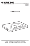
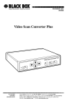
AC500A
AC500AE
AC501A
AC501AE
APRIL 2000
AC502A
AC502AE
AC503A
AC503AE
CAT5 VGA Video Splitter
deo
CAT5 Vi
Remote
Splitter
plitter
CAT5
ideo S
VGA V
Remote
LR
tter
o Spli
A Vide el
G
V
5
CAT 2 Chann
r
litte
eo Sp
GA Vid
l
V
e
5
n
T
n
CA
4 Cha
CUSTOMER
SUPPORT
INFORMATION
Order toll-free in the U.S. 24 hours, 7 A.M. Monday to midnight Friday: 877-877-BBOX
FREE technical support, 24 hours a day, 7 days a week: Call 724-746-5500 or fax 724-746-0746
Mail order: Black Box Corporation, 1000 Park Drive, Lawrence, PA 15055-1018
Web site: www.blackbox.com • E-mail: [email protected]
FCC INFORMATION
FEDERAL COMMUNICATIONS COMMISSION
AND
CANADIAN DEPARTMENT OF COMMUNICATIONS
RADIO FREQUENCY INTERFERENCE STATEMENTS
This equipment generates, uses, and can radiate radio frequency energy and if not
installed and used properly, that is, in strict accordance with the manufacturer’s
instructions, may cause interference to radio communication. It has been tested
and found to comply with the limits for a Class A computing device in accordance
with the specifications in Subpart J of Part 15 of FCC rules, which are designed to
provide reasonable protection against such interference when the equipment is
operated in a commercial environment. Operation of this equipment in a
residential area is likely to cause interference, in which case the user at his own
expense will be required to take whatever measures may be necessary to correct the
interference.
Changes or modifications not expressly approved by the party responsible for
compliance could void the user’s authority to operate the equipment.
This digital apparatus does not exceed the Class A limits for radio noise emission from digital
apparatus set out in the Radio Interference Regulation of Industry Canada.
Le présent appareil numérique n’émet pas de bruits radioélectriques dépassant les limites
applicables aux appareils numériques de la classe A prescrites dans le Règlement sur le
brouillage radioélectrique publié par Industrie Canada.
1
CAT 5 VGA VIDEO SPLITTER
NORMAS OFICIALES MEXICANAS (NOM)
ELECTRICAL SAFETY STATEMENT
INSTRUCCIONES DE SEGURIDAD
1. Todas las instrucciones de seguridad y operación deberán ser leídas antes de
que el aparato eléctrico sea operado.
2. Las instrucciones de seguridad y operación deberán ser guardadas para
referencia futura.
3. Todas las advertencias en el aparato eléctrico y en sus instrucciones de
operación deben ser respetadas.
4. Todas las instrucciones de operación y uso deben ser seguidas.
5. El aparato eléctrico no deberá ser usado cerca del agua—por ejemplo, cerca
de la tina de baño, lavabo, sótano mojado o cerca de una alberca, etc..
6. El aparato eléctrico debe ser usado únicamente con carritos o pedestales que
sean recomendados por el fabricante.
7. El aparato eléctrico debe ser montado a la pared o al techo sólo como sea
recomendado por el fabricante.
8. Servicio—El usuario no debe intentar dar servicio al equipo eléctrico más allá
a lo descrito en las instrucciones de operación. Todo otro servicio deberá ser
referido a personal de servicio calificado.
9. El aparato eléctrico debe ser situado de tal manera que su posición no
interfiera su uso. La colocación del aparato eléctrico sobre una cama, sofá,
alfombra o superficie similar puede bloquea la ventilación, no se debe colocar
en libreros o gabinetes que impidan el flujo de aire por los orificios de
ventilación.
10. El equipo eléctrico deber ser situado fuera del alcance de fuentes de calor
como radiadores, registros de calor, estufas u otros aparatos (incluyendo
amplificadores) que producen calor.
11. El aparato eléctrico deberá ser connectado a una fuente de poder sólo del
tipo descrito en el instructivo de operación, o como se indique en el aparato.
2
NOM STATEMENT
12. Precaución debe ser tomada de tal manera que la tierra fisica y la polarización
del equipo no sea eliminada.
13. Los cables de la fuente de poder deben ser guiados de tal manera que no
sean pisados ni pellizcados por objetos colocados sobre o contra ellos,
poniendo particular atención a los contactos y receptáculos donde salen del
aparato.
14. El equipo eléctrico debe ser limpiado únicamente de acuerdo a las
recomendaciones del fabricante.
15. En caso de existir, una antena externa deberá ser localizada lejos de las lineas
de energia.
16. El cable de corriente deberá ser desconectado del cuando el equipo no sea
usado por un largo periodo de tiempo.
17. Cuidado debe ser tomado de tal manera que objectos liquidos no sean
derramados sobre la cubierta u orificios de ventilación.
18. Servicio por personal calificado deberá ser provisto cuando:
A: El cable de poder o el contacto ha sido dañado; u
B: Objectos han caído o líquido ha sido derramado dentro del aparato; o
C: El aparato ha sido expuesto a la lluvia; o
D: El aparato parece no operar normalmente o muestra un cambio en su
desempeño; o
E: El aparato ha sido tirado o su cubierta ha sido dañada.
3
CAT 5 VGA VIDEO SPLITTER
TRADEMARKS
AT and PS/2 are registered trademarks of International Business Machines
Corporation. Any other trademarks and registered trademarks mentioned in this
manual are acknowledged to be the property of the trademark owners.
4
CONTENTS
CONTENTS
1. Specifications . . . . . . . . . . . . . . . . . . . . . . . . . . . . . . . . . . . . . . . . . . . . . 6
2. Introduction . . . . . . . . . . . . . . . . . . . . . . . . . . . . . . . . . . . . . . . . . . . . . . 7
2.1 Overview . . . . . . . . . . . . . . . . . . . . . . . . . . . . . . . . . . . . . . . . . . . . . . 7
2.2 How to Use this Manual . . . . . . . . . . . . . . . . . . . . . . . . . . . . . . . . . . 7
2.3 What the Package Includes . . . . . . . . . . . . . . . . . . . . . . . . . . . . . . . 7
2.3.1 2-Port CAT5 VGA Video Splitter . . . . . . . . . . . . . . . . . . . . . . 7
2.3.2 4-Port CAT5 VGA Video Splitter . . . . . . . . . . . . . . . . . . . . . . 8
2.3.3 Remote CAT5 VGA Video Splitter . . . . . . . . . . . . . . . . . . . . . 8
2.3.4 Remote Long-Range CAT5 VGA Video Splitter . . . . . . . . . . 8
2.4 Typical Applications . . . . . . . . . . . . . . . . . . . . . . . . . . . . . . . . . . . . . 9
3. Installation . . . . . . . . . . . . . . . . . . . . . . . . . . . . . . . . . . . . . . . . . . . . . . . 11
3.1 Setting the DIP Switches. . . . . . . . . . . . . . . . . . . . . . . . . . . . . . . . . . 11
3.2 Installing the System Cables. . . . . . . . . . . . . . . . . . . . . . . . . . . . . . . 12
3.2.1 Connecting the 2-Port CAT5 VGA Video Splitter
(Central Unit). . . . . . . . . . . . . . . . . . . . . . . . . . . . . . . . . . . . . 13
3.2.2 Connecting the 4-Port CAT5 VGA Video Splitter
(Central Unit). . . . . . . . . . . . . . . . . . . . . . . . . . . . . . . . . . . . . 13
3.3 Installing the Screen Cables. . . . . . . . . . . . . . . . . . . . . . . . . . . . . . . 13
3.3.1 Connecting the 2-Port CAT5 VGA Video Splitter
and Remote Units. . . . . . . . . . . . . . . . . . . . . . . . . . . . . . . . . . 14
3.3.2 Connecting the 4-Port CAT5 VGA Video Splitter
and Remote Units. . . . . . . . . . . . . . . . . . . . . . . . . . . . . . . . . . 15
3.4 Connecting to the Power Supply . . . . . . . . . . . . . . . . . . . . . . . . . . . 15
4. Operation . . . . . . . . . . . . . . . . . . . . . . . . . . . . . . . . . . . . . . . . . . . . . . . . 17
4.1 2-Port CAT5 VGA Video Splitter . . . . . . . . . . . . . . . . . . . . . . . . . . . 17
4.1.1 Front Panel . . . . . . . . . . . . . . . . . . . . . . . . . . . . . . . . . . . . . . . 17
4.1.2 Rear Panel . . . . . . . . . . . . . . . . . . . . . . . . . . . . . . . . . . . . . . . . 18
4.2 4-Port CAT5 VGA Video Splitter . . . . . . . . . . . . . . . . . . . . . . . . . . . 19
4.2.1 Front Panel . . . . . . . . . . . . . . . . . . . . . . . . . . . . . . . . . . . . . . . 19
4.2.2 Rear Panel . . . . . . . . . . . . . . . . . . . . . . . . . . . . . . . . . . . . . . . . 20
4.3 Remote CAT5 VGA Video Splitter . . . . . . . . . . . . . . . . . . . . . . . . . 21
4.3.1 Front Panel . . . . . . . . . . . . . . . . . . . . . . . . . . . . . . . . . . . . . . . 21
4.3.2 Rear Panel . . . . . . . . . . . . . . . . . . . . . . . . . . . . . . . . . . . . . . . . 21
4.4 Long-Range Remote CAT5 VGA Video Splitter. . . . . . . . . . . . . . . 22
4.4.1 Front Panel . . . . . . . . . . . . . . . . . . . . . . . . . . . . . . . . . . . . . . . 22
4.4.2 Rear Panel . . . . . . . . . . . . . . . . . . . . . . . . . . . . . . . . . . . . . . . . 23
4.5 Switching On the Units . . . . . . . . . . . . . . . . . . . . . . . . . . . . . . . . . . 23
5
CAT 5 VGA VIDEO SPLITTER
1. Specifications
System Requirements—2-Channel models: (1) PC, (1) local monitor, (2) remote
monitors; 4-Channel models: (1) PC, (1) local monitor, (4) remote monitors
I/O Signals—Video signals: Red, Green, Blue, 0.7Vp-p/75 ohms positive; Sync:
TTL Vertical and Horizontal
Resolution—Monitor: 1280 x 1024, Horizontal: 30 to 100 kHz, Vertical: 43 to 100
Hz
Transmission—Remote: Splitter to Monitor: 360 ft. (110 m); Remote LR: 820 ft.
(250 m)
Cables—4-pair Category 5 twisted pair, 24 AWG
Connectors—AC500A(E): (1) HD15 male, (1) HD15 female, (2) RJ-45;
AC501A(E): (1) HD15 male, (1) HD15 female, (4) RJ-45;
AC502A(E), AC503A(E): (1) HD15 female, (1) RJ-45
Enclosure—Shielded metal box
Size—AC500A(E), AC501A(E): 1.6”H x 7.7”W x 4.1”D (4.1 x 19.6 x 10.4 cm);
AC502A(E): 1.6”H x 4.4”W x 3.5”D (4.1 x 11.2 x 8.9 cm); AC503A(E): 1.6"H x
6.3"W x 5"D (4.1 x 16 x 12.7 cm)
6
CHAPTER 2: Introduction
2. Introduction
2.1 Overview
The CAT 5 VGA Video Splitter simultaneously distributes a CPU’s picture to
several monitors at up to 360 ft. (110m) using CAT5 UTP Cables—without losing
any picture quality.
The CAT 5 VGA Video Splitter supports:
• AT, PS/2, or PC/XT computers
• VGA, SVGA, or XGA video standards
2.2 How to Use this Manual
This manual is divided into four chapters:
• Chapter 1, Specifications, lists technical specifications for the units.
• Chapter 2, Introduction (this chapter), describes the Video Splitter, what the
package includes, and how to use this manual.
• Chapter 3, Installation, explains how to install the Video Splitter System. It also
illustrates and explains the front and rear panels of both local and remote
units.
• Chapter 4, Operation, describes the front panel operations and the rear panel
connections of the CAT 5 VGA Video Splitter.
If, after reading this manual, you have questions, please call Black Box
Technical Support at 724-746-5500.
2.3 What the Package Includes
Your package should include the following items. If anything is missing or
damaged, please contact Black Box at 724-746-5500.
2.3.1 2-PORT CAT5 VGA VIDEO SPLITTER
The 2-Port host module (AC500A or AC500AE) comes with:
• (1) 2-Port CAT 5 VGA Video Splitter
7
CAT 5 VGA VIDEO SPLITTER
• (1) DB15 HD male to DB15 HD female screen cable
• 110- (for AC500A) or 220-VAC (for AC500AE) power supply
• Power cord
• This user manual
2.3.2 4-PORT CAT5 VGA VIDEO SPLITTER
The 4-Port host module (AC501A or AC501AE) comes with:
• (1) 4-Port CAT 5 VGA Video Splitter
• (1) DB15 HD male to DB15 HD female screen cable
• 110- (for AC501A) or 220-VAC (for AC501AE) power supply
• Power cord
• This user manual
2.3.3 REMOTE CAT5 VGA VIDEO SPLITTER
You’ll need one Remote or Remote Long-Range Splitter for each monitor you wish
to connect. This model (AC502A or AC502AE) lets you connect the remote unit
up to 360 ft. (109.7 m) away from the host. For longer distances, choose the longrange model described in Section 2.3.4.
• (1) Remote CAT5 VGA Video Splitter
• 110- (for AC502A) or 220-VAC (for AC502AE) power supply
• Power cord
• This user manual
2.3.4 REMOTE LONG-RANGE CAT5 VGA VIDEO SPLITTER
You’ll need one Remote or Remote Long-Range Splitter for each monitor you wish
to connect. This model (AC503A or AC503AE) lets you connect the remote unit
up to 820 ft. (249.9 m) away from the host.
• (1) Remote Long-Range CAT5 VGA Video Splitter
• 110- (for AC503A) or 220-VAC (for AC503AE) power supply
8
CHAPTER 2: Introduction
• Power cord
• This user manual
2.4 Typical Applications
Figure 2-1 shows a 2-Port VGA Video Splitter (central unit) broadcasting data to
two remote monitors via two Remote CAT5 VGA Video Splitters or Remote LongRange CAT5 VGA Video Splitters.
Optional keyboard,
mouse, and screen
Remote Unit
(AC502A or
AC503A)
Screen
cable
Monitor
Central Unit
(AC500A)
Remote Unit
(AC502A or
AC503A)
Monitor
Figure 2-1. Typical Application of the 2-Port VGA Video Splitter.
9
CAT 5 VGA VIDEO SPLITTER
Figure 2-2 shows a 4-Port VGA Video Splitter (central unit) broadcasting data to
two remote monitors via four Remote CAT5 VGA Video Splitters or Remote LongRange CAT5 VGA Video Splitters.
Optional keyboard,
mouse, and screen
Screen cable
Monitor
Remote Unit
(AC502A or AC503A)
Monitor
Remote Unit
(AC502A or AC503A)
Central Unit
(AC501A)
Monitor
Remote Unit
(AC502A or AC503A)
Monitor
Remote Unit
(AC502A or AC503A)
Figure 2-2. Typical Application of the 4-Port VGA Video Splitter.
10
CHAPTER 3: Installation
3. Installation
This chapter describes how to connect the system cables, the screen cable, and the
power supply to the CAT5 Video Splitter System using the Remote CAT5 Video
Splitter or Remote Long-Range CAT5 Video Splitter in conjunction with:
• The 2-Port CAT5 VGA Video Splitter (central unit).
• The 4-Port CAT5 VGA Video Splitter (central unit).
A cabling diagram for the 2-Port central unit appears on page 15.
3.1 Setting the DIP Switches
You can improve the picture quality and sharpness by setting the DIP switches
located on the bottom of the remote unit for coarse adjustment.
1. The bottom of the remote unit contains DIP switches G, B, and R. See
Figure 3-1.
Set DIP switch
positions 1, 2, and 3
as described in
Table 3-1. Position
4 on each DIP
switch G, B, and R
is not used.
This DIP
switch is
not used.
Figure 3-1. DIP Switch Settings for Coarse Adjustment.
2. RGB compensation demands identical settings for all three DIP switches.
Table 3-1 defines the appropriate DIP switch settings.
NOTE
Set positions 1, 2, and 3 of DIP switches R, G, and B as described in
Table 3-1. Position 4 on each of the 3 DIP switches is not used.
11
CAT 5 VGA VIDEO SPLITTER
Table 3-1. Screen Resolution and Refresh Rates
Cable Length
meters feet
640x480
75 Hz
800x600
75 Hz
1024x768
75 Hz
1280x1024
75 Hz
50
100
165
330
150
490
200
650
250
820
*300
*980
1, 2, 3—OFF
1—ON,
2, 3—OFF
1—ON,
2, 3—OFF
1—ON,
2, 3—OFF
1, 2—OFF,
3—ON
1, 3—ON,
2—OFF
1, 2, 3—ON
1, 2, 3—OFF
1—ON,
2, 3—OFF
1—ON,
2, 3—OFF
1—ON,
2, 3—OFF
1, 2—OFF,
3—ON
1, 3—ON
2—OFF
1, 2, 3—ON
1, 2, 3—OFF
1—ON,
2, 3—OFF
1—ON,
2, 3—OFF
1—ON,
2, 3—OFF
1, 2—OFF,
3—ON
—
1, 2, 3—OFF
1—ON,
2, 3—OFF
1—ON,
2, 3—OFF
1—ON,
2, 3—OFF
1, 2—OFF,
3—ON
—
—
—
*450 *1475
*NOTE
Use Potentiometer PIC for fine-tuning the picture‘s quality, and
Potentiometer BR for fine-tuning the picture’s brightness.
3.2 Installing the System Cables
The system cable you received with each remote unit you ordered is a single 4-pair
CAT5 UTP Cable with two RJ-45 male connectors attached at each end, as shown
in Figure 3-2.
RJ-45 male
connector
RJ-45 male
connector
Figure 3-2. System Cable.
12
CHAPTER 3: Installation
One system cable connects each remote unit to each system port on the central
unit’s rear panel.
3.2.1 CONNECTING THE 2-PORT CAT5 VGA VIDEO SPLITTER (CENTRAL UNIT)
You need to use two System Cables.
To connect the System Cables
1. Connect one of the system cable’s RJ-45 male connectors to the System 1 port
on the central unit’s rear panel.
2. Connect the other system cable’s RJ-45 male connector to the System port on
the rear panel of Remote Unit # 1.
3. Connect the second system cable’s RJ-45 male connector to the System 2 port
on the central unit’s rear panel.
4. Connect the second system cable’s RJ-45 male other connector to the System
port on the rear panel of Remote Unit # 2.
3.2.2 CONNECTING THE CENTRAL UNIT WITH FOUR PORTS
You need to use four system cables.
To connect the System Cables:
1. Connect one of the system cable’s RJ-45 male connectors to the System 1 port
on the central unit’s rear panel.
2. Connect the other system cable’s RJ-45 male connector to the System port on
the rear panel of Remote Unit # 1.
3. Repeat this scenario with the other three system cables—connecting the
central unit’s System 2, System 3, and System 4 ports to the System ports of
Remote Units #2, #3, and #4, respectively.
3.3 Installing the Screen Cable
The Screen Cable has a DB15HD male connector attached at one end, and a
DB15HD female connector attached at the other end, as Figure 3-3 illustrates.
13
CAT 5 VGA VIDEO SPLITTER
DB15HD
female
DB15HD
male
Figure 3-3. The Screen Cable.
The Screen Cable connects the 2- or 4-Port CAT5 VGA Video Splitter central
unit to the CPU.
As an option, you can link a display screen to the CPU by connecting the display
screen to the Screen Out port on the central unit’s rear panel. You can also
connect a keyboard and mouse to the CPU, which lets you update the data display
on each remote display screen.
3.3.1 CONNECTING THE 2-PORT CAT5 VGA VIDEO SPLITTER AND REMOTE UNITS
Use a screen cable to connect the central unit to the CPU, and to connect each
remote display screen to its corresponding remote unit.
To connect the screen cable to the central unit:
1. Connect the screen cable’s DB15HD male connector to the DB15HD female
screen port of the CPU.
2. Connect the screen cable’s DB15HD female connector to the Screen In port
on the central unit ’s rear panel.
Optionally:
1. Connect the DB15HD male connector from the display screen to the Screen
Out port on the central unit’s rear panel.
To connect the screen cable to the remote unit:
1. Connect the DB15HD male connector from Remote Display Screen # 1 to the
DB15HD female screen port on the rear panel of the Remote Unit # 1.
14
CHAPTER 3: Installation
2. Connect the DB15HD male connector from Remote Display Screen # 2 to the
DB15HD female screen port on the rear panel of the Remote Unit # 2.
3.3.2 CONNECTING THE 4-PORT CAT5 VGA VIDEO SPLITTER AND REMOTE UNITS
Use a screen cable to connect the central unit to the CPU, and to connect each
remote display screen to its corresponding remote unit.
To connect the screen cable to the central unit:
1. Connect the screen cable’s DB15HD male connector to the DB15HD female
screen port of the CPU.
2. Connect the screen cable’s DB15HD female connector to the Screen In port
on the central unit’s rear panel.
Optionally:
1. Connect the DB15HD male connector from the display screen to the Screen
Out port on the central unit’s rear panel.
To connect the screen cable to the remote unit:
1. Connect the DB15HD male connector from Remote Display Screen # 1 to the
DB15HD female screen port on the rear panel of Remote Unit # 1.
2. Repeat this scenario with the other three Remote Display Screens, connecting
the DB15HD male connectors from Remote Display Screens #2, #3, and #4 to
the DB15HD female screen ports on the rear panels of Remote Units # 2, #3,
and #4, respectively.
3.3 Connecting to the Power Supply
Connect each of the units—the 2- or 4-Port CAT5 VGA Video Splitter central unit,
and the Remote or Remote Long-Range CAT5 VGA Video Splitters—to the power
supply in the following way.
To connect each unit to the power supply:
1. Connect the 9-VAC adapter plug to the power-cable connector.
2. Connect the power cable to the 9-VAC adapter and insert the mains plug into
a wall socket. The unit is connected to the power supply.
15
CAT 5 VGA VIDEO SPLITTER
Power
Supply
To Wall Socket
UTP Video
Splitter Unit
Figure 3-4. The Power Supply Block Diagram.
Optional
keyboard,
screen, and
mouse
Power
Supply
To wall socket
Central unit (AC500A)
CPU
Screen cable
UTP CAT5 system cable
Power
Supply
To wall socket
Power
Supply
To wall socket
Figure 3-5. Cabling Diagram for the CAT5 VGA Video Splitter System.
16
CHAPTER 4: Operation
4. Operation
This chapter describes the front panel operations, and the rear panel connections
of the following:
• 2-Port CAT5 VGA Video Splitter (central unit)
• 4-Port CAT5 VGA Video Splitter (central unit)
• Remote CAT5 VGA Video Splitter
• Remote Long-Range CAT5 VGA Video Splitter
4.1 2-Port CAT5 VGA Video Splitter (central unit)
4.1.1 FRONT PANEL
Figure 4-1 illustrates the front panel of the 2-port central unit.
Figure 4-1. Front Panel of the 2-Port Central Unit.
Push the power switch to switch the power ON or OFF.
17
CAT 5 VGA VIDEO SPLITTER
4.1.2 REAR PANEL
Figure 4-2 illustrates the rear panel of the 2-port central unit. Table 4-1 describes
the basic hardware connections.
Power
Screen in
Screen out
System
Figure 4-2. Rear Panel of the 2-Port Central Unit.
Table 4-1. Connectors on the Rear Panel of the 2-Port Central Unit.
18
Connector
Function
Power
Connect the 110 or 220 VAC 9-VAC 1.5-A
adapter’s power cable to this connector.
Screen In
Connect the screen cable’s DB15HD female
connector to this port.
Screen Out
Connect the DB15HD male connector from the
display screen to this port.
System #
Connect the system cable’s connector to this
port.
CHAPTER 4: Operation
4.2 4-Port CAT5 VGA Video Splitter (central unit)
4.2.1 FRONT PANEL
Figure 4-3 illustrates the front panel of the 4-port central unit.
Figure 4-3. Front Panel of the 4-Port Central Unit.
Push the power switch to switch the power ON or OFF.
19
CAT 5 VGA VIDEO SPLITTER
4.2.2 REAR PANEL
Figure 4-4 illustrates the rear panel of the 4-port central unit. Table 4-2 describes
the basic hardware connections.
Power
Screen in
Screen out
System connectors
Figure 4-4. Rear Panel of the 4-Port Central Unit.
Table 4-2. Connectors on the Rear Panel of the 4-Port Central Unit.
20
Connector
Function
Power
Connect the 110 or 220 VAC 9-VAC 1.5-A
adapter’s power cable to this connector.
Screen In
Connect the screen cable’s DB15HD female
connector to this port.
Screen Out
Connect the DB15HD male connector from the
display screen to this port.
System #
Connect the system cable’s connector to this
port.
CHAPTER 4: Operation
4.3 Remote CAT5 VGA Video Splitter
4.3.1 FRONT PANEL
Figure 4-5 illustrates the front panel of the Remote CAT5 VGA Video Splitter.
Figure 4-5. Front Panel of the Remote Unit.
Push the power switch to switch the power ON or OFF.
4.3.2 REAR PANEL
Figure 4-6 illustrates the rear panel of the remote unit. Table 4-3 describes the
basic hardware connections.
Power
Screen
System
Figure 4-6. Rear Panel of the Remote Unit.
21
CAT 5 VGA VIDEO SPLITTER
Table 4-3. Connectors on the Rear Panel of the Remote Unit.
Connector
Function
Power
Connect the 110 or 220 VAC 9-VAC 1.5-A
adapter’s power cable to this connector.
Screen
Connect the display screen’s connector to this
port.
System #
Connect the system cable’s connector to this
port.
4.4 Remote Long-Range CAT5 VGA Video Splitter
4.4.1 FRONT PANEL
Figure 4-7 illustrates the front panel of the Remote Long-Range CAT5 VGA Video
Splitter.
Figure 4-7. Front Panel of the Remote Long-Range Unit.
Push the power switch to switch the power ON or OFF.
22
CHAPTER 4: Operation
4.4.2 REAR PANEL
Figure 4-8 illustrates the rear panel of the remote long-range unit. Table 4-4
describes the basic hardware connections.
Power
Screen
System
Figure 4-8. Rear Panel of the Remote Long-Range Unit.
Table 4-4. Connectors on the Rear Panel of the Remote Long-Range Unit.
Connector
Function
Power
Connect the 110 or 220 VAC 9-VAC 1.5-A
adapter’s power cable to this connector.
Screen
Connect the display screen’s connector to this
port.
System #
Connect the system cable’s connector to this
port.
4.5 Switching On the Units
When the CAT5 VGA Video Splitter system is properly connected, you’re ready to
switch on the each of the units—the CPU, the central unit, the remote units, and
the remote display screens. You can switch them on in any order.
Each remote display screen shows the CPU’s data simultaneously.
23
© Copyright 2000. Black Box Corporation. All rights reserved.
1000 Park Drive
•
Lawrence, PA 15055-1018
•
724-746-5500
•
Fax 724-746-0746