1
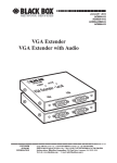
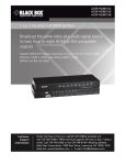
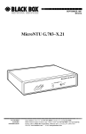
FEBRUARY 1996
MX700A
Digi-Mux HS
L
LOCAP
LOO
ux HS
igi-M
D
CH1
RD
CH2
RD
TD
CH3
RD
TD
CH4
RD
TD
MAIN
DCD
RD
TEST
SYNC
LOSS
TD
TD
ER
POW
CUSTOMER
SUPPORT
INFORMATION
Order toll-free in the U.S.: Call 877-877-BBOX (outside U.S. call 724-746-5500)
FREE technical support 24 hours a day, 7 days a week: Call 724-746-5500 or fax 724-746-0746
Mailing address: Black Box Corporation, 1000 Park Drive, Lawrence, PA 15055-1018
Web site: www.blackbox.com • E-mail: [email protected]
FCC STATEMENT
FEDERAL COMMUNICATIONS COMMISSION
AND
INDUSTRY CANADA
RADIO FREQUENCY INTERFERENCE STATEMENTS
This equipment generates, uses, and can radiate radio-frequency energy, and if not
installed and used properly, that is, in strict accordance with the manufacturer’s
instructions, may cause interference to radio communication. It has been tested
and found to comply with the limits for a Class A computing device in accordance
with the specifications in Subpart B of Part 15 of FCC rules, which are designed to
provide reasonable protection against such interference when the equipment is
operated in a commercial environment. Operation of this equipment in a
residential area is likely to cause interference, in which case the user at his own
expense will be required to take whatever measures may be necessary to correct
the interference.
Changes or modifications not expressly approved by the party responsible
for compliance could void the user’s authority to operate the equipment.
This digital apparatus does not exceed the Class A limits for radio noise emission from
digital apparatus set out in the Radio Interference Regulation of Industry Canada.
Le présent appareil numérique n’émet pas de bruits radioélectriques dépassant les limites
applicables aux appareils numériques de la classe A prescrites dans le Règlement sur le
brouillage radioélectrique publié par Industrie Canada.
1
DIGI-MUX HS
NORMAS OFICIALES MEXICANAS (NOM)
ELECTRICAL SAFETY STATEMENT
INSTRUCCIONES DE SEGURIDAD
1. Todas las instrucciones de seguridad y operación deberán ser leídas antes de
que el aparato eléctrico sea operado.
2. Las instrucciones de seguridad y operación deberán ser guardadas para
referencia futura.
3. Todas las advertencias en el aparato eléctrico y en sus instrucciones de
operación deben ser respetadas.
4. Todas las instrucciones de operación y uso deben ser seguidas.
5. El aparato eléctrico no deberá ser usado cerca del agua—por ejemplo, cerca
de la tina de baño, lavabo, sótano mojado o cerca de una alberca, etc..
6. El aparato eléctrico debe ser usado únicamente con carritos o pedestales que
sean recomendados por el fabricante.
7. El aparato eléctrico debe ser montado a la pared o al techo sólo como sea
recomendado por el fabricante.
8. Servicio—El usuario no debe intentar dar servicio al equipo eléctrico más allá
a lo descrito en las instrucciones de operación. Todo otro servicio deberá ser
referido a personal de servicio calificado.
9. El aparato eléctrico debe ser situado de tal manera que su posición no
interfiera su uso. La colocación del aparato eléctrico sobre una cama, sofá,
alfombra o superficie similar puede bloquea la ventilación, no se debe colocar
en libreros o gabinetes que impidan el flujo de aire por los orificios de
ventilación.
10. El equipo eléctrico deber ser situado fuera del alcance de fuentes de calor
como radiadores, registros de calor, estufas u otros aparatos (incluyendo
amplificadores) que producen calor.
11. El aparato eléctrico deberá ser connectado a una fuente de poder sólo del
tipo descrito en el instructivo de operación, o como se indique en el aparato.
2
NOM STATEMENT
12. Precaución debe ser tomada de tal manera que la tierra fisica y la polarización
del equipo no sea eliminada.
13. Los cables de la fuente de poder deben ser guiados de tal manera que no
sean pisados ni pellizcados por objetos colocados sobre o contra ellos,
poniendo particular atención a los contactos y receptáculos donde salen del
aparato.
14. El equipo eléctrico debe ser limpiado únicamente de acuerdo a las
recomendaciones del fabricante.
15. En caso de existir, una antena externa deberá ser localizada lejos de las lineas
de energia.
16. El cable de corriente deberá ser desconectado del cuando el equipo no sea
usado por un largo periodo de tiempo.
17. Cuidado debe ser tomado de tal manera que objectos liquidos no sean
derramados sobre la cubierta u orificios de ventilación.
18. Servicio por personal calificado deberá ser provisto cuando:
A: El cable de poder o el contacto ha sido dañado; u
B: Objectos han caído o líquido ha sido derramado dentro del aparato; o
C: El aparato ha sido expuesto a la lluvia; o
D: El aparato parece no operar normalmente o muestra un cambio en su
desempeño; o
E: El aparato ha sido tirado o su cubierta ha sido dañada.
3
DIGI-MUX HS
TRADEMARKS USED IN THIS MANUAL
Any trademarks mentioned in this manual are acknowledged to be the property of the
trademark owners.
4
CONTENTS
Contents
Chapter
Page
1. Specifications ................................................................................................6
2. Introduction..................................................................................................7
2.1 General Description .............................................................................7
2.2 Functional Description and Applications ...........................................7
2.2.1 Multiplexing ...............................................................................7
2.2.2 Synchronization..........................................................................7
2.2.3 Timing.........................................................................................8
2.2.4 Diagnostics..................................................................................9
2.2.5 DCE/DTE Selection...................................................................9
3. Installation ....................................................................................................10
3.1 General..................................................................................................10
3.2 Preparing the Site.................................................................................10
3.3 Mechanical Assembly............................................................................10
3.4 Electrical Installation............................................................................10
3.4.1 AC Power Cord ...........................................................................10
3.4.2 Rear-Panel Connectors ..............................................................10
3.4.3 Strap Selection............................................................................10
3.4.4 Changing Internal Jumpers and Switches ................................11
4. Operation......................................................................................................16
4.1 General..................................................................................................16
4.2 Control ..................................................................................................17
4.3 Indicators ..............................................................................................17
4.4 Operating Procedure ...........................................................................19
4.4.1 Power On ....................................................................................19
4.4.2 Self-Test.......................................................................................19
4.4.3 Operation ...................................................................................19
4.4.4 Power Off ....................................................................................19
4.5 Reconfiguring .......................................................................................19
5. Testing...........................................................................................................20
5
DIGI-MUX HS
1. Specifications
Multiplexor Technique—Time-division, interleaved
Protocol—Synchronous
Speed—Link: Up to 2.048 Mbps (with no bit-timing on Channel 4, selectable
rates up to 2.048 Mbps); Channel: A 25% split per channel; a 50/25/25
split between channels 1, 2, and 4; a 50/50 split between channels 1 and 4;
a 75/25 split between channels 1 and 4
Interface—V.35
Connectors—(5) V.35 34-pin female
Indicators—Channels: Transmit (TD), Receive (RD);
Link: Transmit (TD), Receive (RD), Data Carrier Detect, Synchronization
Loss, TEST
Configuration—Link: DTE externally clocked;
Link: Channels 1, 2, and 3: DCE or DTE; Channel 4: DCE only
Diagnostics—Local loop
Temperature—32 to 122°F (0 to 50°C)
Humidity—Up to 90%, non-condensing
Power—115/230 VAC, 42 to 63 Hz, 10 watts
Size—1.7"H x 17"W x 8.2"D (4.3 x 43.2 x 20.8 cm)
Weight—4.4 lb. (2 kg)
6
CHAPTER 2: Introduction
2. Introduction
2.1 General Description
The Digi-Mux HS is a high-speed, bit-interleaved time division multiplexor,
enabling up to four channels to be multiplexed onto the trunk line of a
Digital Data Service or modem. It can multiplex two, three or four channels
onto one link without overhead. For example, four data sources (such as
computers, controllers or multiplexors) operating at a data rate of 64 kbps
can share a single modem or DDS link at a data rate of 256 kbps. The DigiMux HS provides full-duplex synchronous operation at selected data rates
up to 2048 kbps.
2.2 Functional Description and Applications
2.2.1 MULTIPLEXING
The Digi-Mux HS selects one data bit from each active channel and serially
transmits the combined data stream over the high speed link. At the receive
end, it reverses the procedure, allocating each data bit to its respective
channel.
2.2.2 SYNCHRONIZATION
The Digi-Mux HS uses one bit in every 2048 bits on the main link to
synchronize the data, while it takes bit-time from channel 4 bandwidth.
Though this does not result in loss of data, it does prevent connection
of a tail-end circuit or DTE equipment that cannot tolerate clock-phase
discontinuity to channel 4 (e.g. other TDM multiplexors).
Synchronization occurs in 3 stages.
Stage 1
The Digi-Mux HS sends a synchronization bit every 4096 bits and waits to
receive a similar bit from the remote Digi-Mux HS (within every 4096 bits).
After receiving a synchronization bit it advances to the next step.
Stage 2
The Digi-Mux HS sends a synchronization bit every 2048 bits and waits
to receive a similar bit from the remote Digi-Mux HS before advancing
to step 3.
NOTE
As long as the Digi-Mux HS receives a synchronization bit every 4096
bits, it remains in stage 2.
7
DIGI-MUX HS
Stage 3
Full synchronization state. The Digi-Mux HS transmits and receives a
synchronization bit every 2048 bits. If it doesn’t receive a synchronization bit
at this value, the unit is out of synchronization, and it stops transmitting to the
remote Digi-Mux HS (over a long period of time), causing the remote to exit
its synchronization state. Both Digi-Mux HSs then revert to stage 1.
The synchronization bit in the main channel is transmitted and received
in the timeslot of channel 4. To stop the data stream during this time period,
the Digi-Mux HS does not send clocks on channel 4.
2.2.3 TIMING
The Digi-Mux HS link rate can be up to 2048 kbps and is externally clocked
from the modem or the Digital Data Service line.
Channel rate is determined as a percentage of the link rate. The Digi-Mux
HS supports four modes:
1. Each channel is allocated 25% of the link rate.
2. Channel 1 is allocated 50%, and channels 2 and 4 are each allocated 25%
of the link rate.
3. Channel 1 and channel 4 are each allocated 50% of the link rate.
4. Channel 1 is allocated 75% of the link rate, and channel 4 is allocated
25% of the link rate.
The clocks to the sub-channels are a division of the main channel clocks,
with the division determined according to the mode of operation.
The clocks of sub-channel 4 are not the regular clocks, because the
synchronization bit produces one missing clock during transmit or
receive periods of the bit. For sub-channel 4 clocks there are 2 options,
for equipment sensitive to discontinuity in the clock phase (missing clock
in the regular clock cycle).
Option 1—Without smoothing:
The clocks are the nominal clocks, while every 2048 clocks a missing
clock occurs.
Option 2—With smoothing:
The clocks will be set with 50% duty cycle and will not be the nominal clocks.
The missing clock period is evenly spread over the other clocks.
8
CHAPTER 2: Introduction
2.2.4 DIAGNOSTICS
To activate the Digi-Mux HS’s local main loop, press the front-panel push
button.
The Digi-Mux HS provides continuous LED monitoring of transmit and
receive data for each channel and link, as well as receive Data Carrier Detect
and Synchronization loss of the link.
2.2.5 DCE/DTE SELECTION
With jumpers, you can set Channels 1, 2 and 3 independently to operate as
DCE or DTE, so you can directly connect tail-end circuits to to the Digi-Mux
HS without a cross cable. Whenever a channel is set as DTE, an elastic buffer
is automatically activated.
Time
Division
Multiplexor
Time
Division
Multiplexor
Digi-Mux
HS
Up to
2.048 bps
CSU/DSU
Digi-Mux
HS
V.35
CSU/DSU
V.35
Figure 2-1. Remote Units Linked to
Central Communication Controller.
9
DIGI-MUX HS
3. Installation
3.1 General
This chapter provides information on the mechanical and electrical
installation of the Digi-Mux HS. To ensure normal operation after
installation, refer to Chapter 4 for operating information and system
checkout.
3.2 Preparing the Site
The Digi-Mux HS should be installed within 5 feet (1.5 m) of a grounded,
easily accessible AC outlet. The outlet should be capable of furnishing 115
VAC or 220 VAC (depending on the power voltage available in your area).
Allow at least 36 in (90 cm) of frontal clearance for operating and
maintenance accessibility. Ensure that there is at least 4 in (10 cm)
clearance at the rear of the unit for signal lines and interface cables.
3.3 Mechanical Assembly
The Digi-Mux HS is designed to be placed on a tabletop or bench, and is
delivered completely assembled. You cannot bolt the Digi-Mux HS to the
tabletop.
3.4 Electrical Installation
3.4.1 AC POWER CORD
AC power is supplied to the Digi-Mux HS through a standard 5-foot (1.5-m)
detachable power cord terminated by a standard 3-prong plug. The power
inlet on the rear panel incorporates an integral fuse.
3.4.2 REAR-PANEL CONNECTORS
The main and sub-channels consist of five 34-pin V.35 interface connectors.
Table 3-1 provides detailed information on these interface connectors.
3.4.3 STRAP SELECTION
After you complete and check the electrical installation, determine the
configuration of the Digi-Mux HS in the data system, and position the
straps as required. The strap locations noted on the PCB Layout Diagram
(Figure 3-1) correspond to the numbers listed under “Strap Identity” in
Table 3-2.
10
CHAPTER 3: Installation
CH1
DCE
DTE
4
CH2
DCE
CH3
DTE
DCE
5
DTE
6
CHSIS. GND
DIS
3
CON
2
1
1 2 3 4
56
01
SW2
MAIN BAUD RATE
SW2-4
OFF
0- 2048
1- 1024
23
2- 512
3- 256
4- 129
5- 64
4
CHANNEL SPLIT (%)
SW2
CHANNEL
1
2
1 2 3 4
ON ON 25 25 25 25
ON OFF 50 25
25
OFF ON 50
50
OFF OFF 75
25
789
CH4 SMOOTHING
SW2-3
ON - YES
OFF - NO
ON
0- 1729
1- 896
2- 448
3- 224
4- 112
5- 56
Figure 3-1. PCB Layout.
3.4.4 CHANGING INTERNAL JUMPERS AND SWITCHES
1. Disconnect the power cable.
2. Loosen the rear screw holding the top cover in place.
3. Remove the top cover.
4. Adjust the jumpers as required.
5. Replace the top cover and tighten the retaining screw.
11
DIGI-MUX HS
Table 3-1. Interface Signal List (female connector).
Signal Function
Pin Circuit
Protective Ground
A
Frame
101
Chassis ground. May be isolated from
signal ground (refer to Table 3-2).
Signal
B
Signal
102
Common signal and DC power-supply
ground.
Transmitted Data
P
S
TD (A)
TD (B)
103
103
Serial digital data from DTE. The data
transition must occur on the rising edge
of the transmit clock.
Received Data
R
T
RD (A) 104
RD (B) 104
Serial digital data to DTE. The data
transition must occur on the rising edge
of the receive clock.
Request to Send
C
RTS
105
A positive level to the Digi-Mux HS
when data transmission is desired.
Clear to Send
D
CTS
106
A positive level from the Digi-Mux HS
after receiving RTS.
Data Set Ready
E
DSR
107
A positive level from the Digi-Mux HS
when power is on.
Data Terminal
Ready
H
DTR
108
Not used.
Carrier Detect
F
DCD
109
A positive level from the Digi-Mux HS.
12
Description
CHAPTER 3: Installation
Table 3-1 (continued). Interface Signal List (female connector).
Signal Function
Pin Circuit
Description
External Transmit
Clock
U SCTE (A) 113
W SCTE (B) 113
A serial data rate clock input from the
data source. Positive clock transition
must correspond to data transition.
Transmit Clock
Y SCT (A)
a SCT (B)
114
114
A transmit data rate clock output for use
by external data sink. Positive clock
transition corresponds to data
transition.
Receive Clock
V SCR (A)
X SCR (B)
115
115
A receive data rate clock output for use
by external data sink. Positive clock
transition corresponds to data
transition.
13
DIGI-MUX HS
Table 3-2. Digi-Mux HS Strap Selection.
Strap Identity Function
Possible Settings
Factory Setting
No. 1
Selects the main
Option 1
Main Channel
channel data rate
(SW2-4=OFF) (SW2-4=ON)
Data Rate
for channel 4
(kbps)
smoothing clocks
No. 2
Selects main
0
2048
Option 2
1792
1
1024
896
2
512
448
3
256
224
4
128
112
5
64
56
256 kbps
Switch
Sub-channel
Channel Split(%) split between the
1
1 2 3 4
SW2-1, SW2-2
2
sub-channels
On On
25 25 25 25
(measured as
On Off
50 25 - 25
a percentage)
Off On
50 -
- 50
Off Off
75 -
- 25
Smoothing
Selects sub-
On: Smoothing clock 50% duty cycle
SW2-3
channel 4’s
Off: Without smoothing clock
25 25 25 25
Off
clock
Main Channel
Selects main
Off: Option 1 (multiple of 64 bps)
Data Rate
channel data
On: Option 2 (multiple of 56 bps)
Off
Option SW2-4
rate option
CON
(for No. 1 above)
No. 3
CON setting
CON
GND
connects Signal
DIS
Ground to Chassis
Ground; DIS
setting isolates them
14
CHAPTER 3: Installation
Table 3-2 (continued). Digi-Mux HS Strap Selection.
Strap Identity Function
Possible Settings
No. 4
Selects equipment DTE for DTE equipment
DTE/DCE
connected to
Factory Setting
DCE
DCE for DCE equipment
sub-channel 1
No. 5
Selects equipment DTE for DTE equipment
DTE/DCE
connected to
DCE
DCE for DCE equipment
sub-channel 2
No. 6
Selects equipment DTE for DTE equipment
DTE/DCE
connected to
DCE
DCE for DCE equipment
sub-channel 3
15
DIGI-MUX HS
4. Operation
4.1 General
This chapter describes the functions of the controls and indicators, and
provides operating instructions and strapping information. You must
complete and check the installation as described in Chapter 3 before you
operate the Digi-Mux HS.
POWER
CH 1
TD RD
CH 2
TD RD
CH 3
TD RD
CH 4
TD RD
TD
MAIN
RD DCD
SYNC
LOSS
Figure 4-1. Digi-Mux HS Front Panel.
16
LOCAL
LOOP
TEST
CHAPTER 4: Operation
4.2 Control
The Local Loop button located on the front panel performs a loop on the
main channel towards the sub-channels. When activated, it loops the transmit
main channel data and clock to its receive data and clock.
4.3 Indicators
All LED indicators are located on the front panel and described in Table 4-1.
The numbers listed under “Item” in Table 4-1 correspond to the
identification numbers in Figure 4-1.
17
DIGI-MUX HS
Table 4-1. Indicators.
Item
Indicator
LED Color
Function
1
POWER
Green
ON when power is on.
2
CH-1 thru
CH-4: TD
Yellow
ON when steady space is transmitted in
sub-channel. Flickers when data is
transmitted.
3
CH-1 thru
CH-4: RD
Yellow
ON when steady space is received in
sub-channel. Flickers when data is
received.
4
MAIN: TD
Yellow
ON when steady space is transmitted in
main channel. Flickers when data is
transmitted.
5
MAIN: RD
Yellow
ON when steady space is received in
main channel. Flickers when data is
received.
6
MAIN: DCD
Yellow
ON when a DCD signal is received from
the main channel modem.
7
SYNC LOSS
Red
ON when Digi-Mux HS does not receive
a synchronization bit from the remote
Digi-Mux HS.
8
TEST
Red
ON when Digi-Mux HS is in loopback.
18
CHAPTER 4: Operation
4.4 Operating Procedure
4.4.1 POWER ON
Apply AC power by connecting the AC power cord to an acceptable AC
source, and place the power button on the rear panel in the ON position.
The power LED should light up, indicating that the Digi-Mux HS is on.
If the local and remote Digi-Mux HS units are connected to modems and
all these units are operating and passing data, the following indicator
conditions should exist:
• POWER: ON
• All sub-channels, TD: Flashing or OFF
• All sub-channels, RD: Flashing or OFF
• Main channel, TD: Flashing
• Main channel, RD: Flashing
• Main channel, DCD: ON
• SYNC LOSS: OFF
• TEST: OFF
4.4.2 SELF-TEST
To verify that the Digi-Mux HS is operating correctly, use the local loopback
test as described in Chapter 5.
4.4.3 OPERATION
The Digi-Mux HS operates entirely unattended, except for occasional
monitoring of the front panel.
4.4.4 POWER OFF
To power off the Digi-Mux HS, simply switch the power button on the rear
panel of the Digi-Mux HS to the OFF position.
4.5 Reconfiguring
If you must reconfigure the Digi-Mux HS for a different type of operation,
you must change the jumpers to correspond to the new operating mode.
See Section 3.4.4.
19
DIGI-MUX HS
5. Testing
This chapter explains how to use the loopback test.
The test switch and front panel indicators built into the Digi-Mux HS allow
rapid checking of the Digi-Mux HS. Use the test procedure provided in this
chapter to verify normal operation and to isolate faulty equipment in the
event of failure.
Before testing the operation of data system equipment circuits, make sure
that all units are turned on and configured correctly.
The test checks the performance of the local multiplexor, the local
equipment attached to the multiplexor, and the cables between them.
It is performed separately at the local and the remote sites.
PROCEDURES
1. Press the LOCAL LOOP button on the front panel. The TEST indicator
should turn on. The Digi-Mux HS’s transmit output is now connected
to its own receive (Figure 5-1).
2. Verify that the equipment attached to the Digi-Mux HS is operating
properly and can be used for test. If a fault is indicated, call a technician
or replace the unit.
3. Execute the test using one of the methods described below:
a. Use the equipment and check the echoed stream.
b. Use an external Bit Error Rate Tester (BERT) unit.
4. Perform step 3 above at both ends. If BERT test equipment indicates
no fault, but the regular equipment does indicate a fault, follow the
manufacturer’s test procedures for the equipment and verify that the
cable connecting the Digi-Mux HS and the equipment is properly
connected and in good condition. After completing the test (or when
the fault has been corrected), press the LOCAL LOOP button again.
The TEST LED should be OFF.
20
CHAPTER 5: Testing
1
Modem
2
TD
TC
RD
RC
Main
Channel
Local
Loopback
DTE/DCE
DTE/DCE
3
DTE/DCE
4
DCE
Digi-Mux HS
Figure 5-1. Digi-Mux HS in Local Loop.
21
© Copyright 1996. Black Box Corporation. All rights reserved.
1000 Park Drive
•
Lawrence, PA 15055-1018
•
724-746-5500
•
Fax 724-746-0746