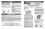
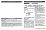
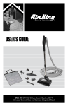
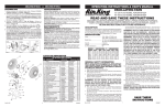
1
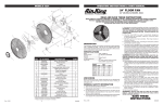
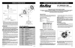
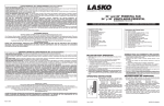
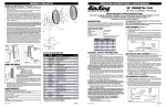
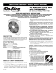
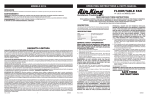
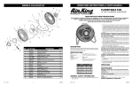
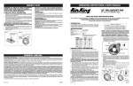
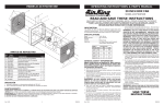
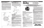
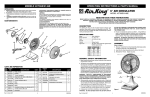
MODELO 6KX43A/9224A
OPERATING INSTRUCTIONS & PARTS MANUAL
24" FLOOR FAN
15
24" (60.96cm) MODEL 6KX43A/9224A
16
8
13
READ AND SAVE THESE INSTRUCTIONS
11
7
12
9
READ CAREFULLY BEFORE ATTEMPTING TO ASSEMBLE, INSTALL, OPERATE OR MAINTAIN THE PRODUCT DESCRIBED.
PROTECT YOURSELF AND OTHERS BY OBSERVING ALL SAFETY INFORMATION. FAILURE TO COMPLY WITH
INSTRUCTIONS COULD RESULT IN PERSONAL INJURY AND/OR PROPERTY DAMAGE!
RETAIN INSTRUCTIONS FOR FUTURE REFERENCE.
10
14
4. Do not insert fingers or foreign objects into the fan. Do not block or
tamper with the fan in any manner while it is in operation. Do not touch
the fan while in operation or just after it has been turned off, as some
parts may be hot enough to cause injury.
5. Unplug power cord before installing or servicing the fan.
WARNING: DO NOT DEPEND UPON THE ON-OFF SWITCH AS THE
SOLE MEANS OF DISCONNECTING POWER WHEN INSTALLING OR
SERVICING THE FAN. ALWAYS UNPLUG THE POWER CORD.
6. This fan is intended for general use ONLY. It must NOT be used in
potentially dangerous locations such as flammable, explosive, chemical-laden or wet atmospheres.
WARNING: TO REDUCE THE RISK OF FIRE OR ELECTRIC SHOCK, DO
NOT USE THIS FAN WITH ANY SOLID STATE SPEED CONTROL DEVICE.
7. Be sure fan is on a stable surface when operating, to avoid chance of
it overturning.
8. DO NOT use fan in a window. Rain may create an electrical hazard.
9. Completely reassemble fan, according to instructions, before
reconnecting to power supply.
CAUTION: BECAUSE OF SIZE AND WEIGHT OF THIS FAN, MAKE
SURE ALL PARTS ARE COMPLETELY ASSEMBLED ACCORDING TO
INSTRUCTIONS. FAILURE TO DO SO COULD RESULT IN FAN COMING
APART DURING OPERATION AND/OR PERSONAL INJURY.
9
6
7
10
4
17
5
2
20
18
DESCRIPTION
19
The AirKing 24" (60.96 cm) pivot/floof fan features 3-speed operation with a
3-paddle fan blade. The fan has a permanently lubricated motor with a 10 ft
(3.05 m) 18/3 cord set, and is constructed of sturdy powder coated steel.
21
3
SPECIFICATIONS
18
17
1
INSTRUCCIONES DE USO
1. Para usar: Enchufe el cordón en un tomacorriente
de 120 V, 60 Hz con puesta a tierra. Seleccione la
velocidad de funcionamiento deseada usando la
perilla en la parte superior del motor.
2. Para ajustar el ángulo del cabezal: El cabezal
permanece inmóvil cuando se gira a la posición
deseada. Puede ser necesario volver a apretar la
tornillería de vez en cuando después de cambiar la
posición del cabezal varias veces.
MANTENIMIENTO
ADVERTENCIA: DESCONECTE SIEMPRE EL
CORDÓN ANTES DE INTENTAR REALIZAR
CUALQUIER FUNCIÓN DE SERVICIO.
LIMPIEZA: Use un trapo y una solución de jabón suave,
tal como detergente líquido para lavar trastes.
ADVERTENCIA: No use gasolina, bencina, diluyente
de pintura ni limpiadores fuertes en aerosol, ya que
éstos dañarán el ventilador.
ALMACENAMIENTO: Cuando no lo utilice, mantenga el
aparato en un lugar limpio y seco.
EL MOTOR HA SIDO PERMANENTEMENTE
LUBRICADO.
Rev. D 7/01
Ref.
1
2
3
4
5
6
7
8
9
10
11
12
13
14
15
16
17
18
19
20
21
NO. DE PARTE
2070004A
5097021BK
5082031CH
5090012
2091212Z
5097020BKT
*
5062086BK
*
*
2030024SK
2030024SW
2030024MTR
2030024CS
5062211BK
5010051
5090050
5010050
5062215BK
5062215BK
2090039
DESCRIPCIÓN
Adorno Tipo Ojo de Buey
Rejilla Delantera
Paleta
Tornillos 5/16-24
Tornillos del motor 10-32 x 5/16
Rejilla Trasera con Placa de
Pivote Con Hexagonal
Perno de 1/4-20 x 3/4
Patas
Arandela de Seguridad
Tuerca de 1/4-20
Perilla del Interruptor
Interruptor
Conjunto del Motor
Juego de Alambre Flexible
Manija
Empuñadura de la manija
Eje tapa Perno
Ruedas
Eje
Escuadra de montaje
Tornillo #8 X 3/8
CANT.
1
1
1
1
5
1
4
2
2
2
1
1
1
1
1
1
2
2
1
1
2
* Articulo Incluyendo el numero de Empaques 5098012
** Patas de caucho con remache no incluidas
4
5084028
TOOLS REQUIRED FOR ASSEMBLY
Motor ....................................... 120V, 50/60 Hz
Blade diameter ........................ 24" (60.96cm) Model 6KX43A/9224A
Speeds .................................... 3
Control .................................... Rotary Switch
Air flow distribution ................. 90˚
Approvals ................................ UL Listed. Close mesh fan guard
meets OSHA requirements.
Model
SPEED
CFM
• (2) 7/16" wrenches or (2) Adjustable Wrenches
• #2 Phillips Head Screwdriver
NOTE: ALL HARDWARE REFERRED TO IN THE INSTRUCTIONS MAY
BE FOUND IN THE SUPPLIED PART BAGS
STAND ASSEMBLY (Figure 1)
1. Remove two stand halves, handle, hardware bag and cardboard tray
from carton.
2. Orient stand halves as illustrated and install one 1/4-20 X 3/4” bolt
thru stand hole and into rear grill pivot bracket to left of motor.
3. Install one 1/4-20 X 3/4” bolt, nut and lock washer in remaining stand
hole to left of motor.
4. While holding handle in position as shown, install one1/4-20 X 3/4” bolt
thru handle, stand and into rear grill pivot bracket to right of motor.
5. Install one 1/4-20 X 3/4” bolt, nut and lockwasher in remaining handle
and stand hole.
6KX43A/9224A
HIGH
MED
LOW
12111
11233
9511
M3/s
5.72
5.30
4.49
RPM
1062
985
834
Amps
2.03
1.81
1.63
Watts
229
200
176
dB A
72
69
64
WHEEL ASSEMBLY (Figure 2)
GENERAL SAFETY INFORMATION
1. Make certain that the power source conforms to the electrical requirements of the fan.
2. The power cord is equipped with a three-prong grounded plug that must be
inserted into a matching receptacle. Under no circumstances must the
grounding prong be cut off the plug. Where a two-prong wall receptacle is
encountered, it must be replaced with a properly grounded three-prong
receptacle installed in accordance with the National
Electrical Code (NEC) and all applicable local codes and ordinances. This
work must be done only by a qualified electrician, using copper wire only.
WARNING: USE OF A THREE-PRONG TO TWO-PRONG ADAPTER IS NOT
RECOMMENDED. IMPROPER CONNECTION MAY CREATE
THE RISK OF ELECTROCUTION. USE OF SUCH ADAPTERS ARE NOT
PERMITTED IN CANADA.
3. Where possible, avoid the use of extension cords. If they must be used, minimize
the risk of overheating by ensuring that they are UL listed and of the proper gage
and length. Never use a single extension cord to operate more than one fan.
Rev. D 7/01
1
1. Remove assembled fan from carton.
2. Place wheel mounting bracket across stand halves to left of
motor as shown.
3. Install two #8 X 3/8 sheet metal screws using a #2 Phillips Head
Screwdriver.
4. Slide axle thru bracket.
5. Install two wheels and two axle cap nuts.
Axle Cap
Nut
Wheel
Axle
Assembled
Stand
Mounting
Bracket
Wheel
Figure 1
Axle Cap
Nut
Figure 2
5084028
MANUAL DE INSTRUCCIONES DE OPERACIÓN Y PARTES
MODEL 6KX43A/9224A
15
VENTILADOR DE PISO
DE 24 PULG
16
8
13
24" (60.96cm) MODELO 6KX43A/9224A
11
7
12
9
LEA Y GUARDE ESTAS INSTRUCCIONES
10
LÉALAS CUIDADOSAMENTE ANTES DE INTENTAR ARMAR, INSTALAR, OPERAR O DAR MANTENIMIENTO AL PRODUCTO
DESCRITO. PROTÉJASE A SÍ MISMO Y A LOS DEMÁS OBSERVANDO TODA LA INFORMACIÓN SOBRE SEGURIDAD. ¡NO
SEGUIR LAS INSTRUCCIONES PODRÍA RESULTAR EN LESIONES PERSONALES Y/O DAÑOS A LA PROPIEDAD!
GUARDE LAS INSTRUCCIONES PARA REFERENCIAS FUTURAS.
14
9
6
4.
No introduzca los dedos ni objetos extraños en el ventilador. No obstruya ni
manipule indebidamente el ventilador mientras esté en operación. No toque el
ventilador mientras esté en operación ni inmediatamente después de haberlo
apagado, ya que ciertas partes podrían estar lo suficientemente calientes como
para causar una lesión.
5. Desenchufe el cordón eléctrico antes de instalar o dar servicio al ventilador.
ADVERTENCIA: NO DEPENDA DEL INTERRUPTOR DE ENCENDIDO Y APAGADO
COMO EL ÚNICO MEDIO PARA INTERRUMPIR LA ALIMENTACIÓN ELÉCTRICA
CUANDO INSTALE O DÉ SERVICIO AL VENTILADOR. SIEMPRE DESENCHUFE
EL CORDÓN ELÉCTRICO.
6. Este ventilador es para uso general EXCLUSIVAMENTE. NO deberá usarse en
localidades potencialmente peligrosas tales como atmósferas inflamables,
explosivas, cargadas de gases o húmedas.
ADVERTENCIA: PARA REDUCIR EL RIESGO DE INCENDIOS O DESCARGAS
ELÉCTRICAS, NO USE ESTE VENTILADOR CON NINGÚN DISPOSITIVO DE
CONTROL DE VELOCIDAD DE ESTADO SÓLIDO.
7. Asegúrese de que el ventilador esté sobre una superficie estable al estar en
funcionamiento, para evitar toda riesgo de que se voltee.
8. NO utilice el ventilador en una ventana, ya que la lluvia podría crear un peligro eléctrico.
9. Vuelva a armar completamente el ventilador, de acuerdo con las instrucciones,
antes de volver a conectarlo a la alimentación eléctrica.
7
10
4
17
5
2
20
18
19
21
3
DESCRIPCIÓN
El ventilador pivotante/de piso AirKing de 24 pulg (60,96 cm) ofrece 3
velocidades de funcionamiento y una hélice de 3 aspas. El ventilador tiene
un motor permanentemente lubricado y un cordón eléctrico calibre 18 con
puesta a tierra de 10 pies (3,05 m) de largo, y está fabricado de acero
duradero con acabado pulverizado.
18
17
ESPECIFICACIONES
1
OPERATING INSTRUCTIONS
1) To Operate: Plug cord into a grounded 120V, 60Hz
outlet. Select desired operating speed with knob on
top of the motor.
2) To Adjust Head Angle: Head will remain stationary
when rotated to desired position. Occasional tightening of pivot hardware may be required after head is
repositioned multiple times.
MAINTENANCE
WARNING: ALWAYS UNPLUG THE CORD BEFORE
SEVICING.
DO NOT IMMERSE FAN IN WATER
CLEANING: Use a soft cloth and a mild soap
solution such as liquid dish washing detergent.
Avoid the use of gasoline, benzine, thinner, harsh
cleaners, etc. which will damage the fan.
Dry all parts with a soft cloth completely before reconnecting
to power supply.
STORAGE: When not in use, keep unit in a clean dry place.
MOTOR IS PERMANENTLY LUBRICATED.
Key
1
2
3
4
5
6
7
8
9
10
11
12
13
14
15
16
17
18
19
20
21
Part Number
2070004A
5097021BK
5082031CH
5090012
2091212Z
5097020BKT
*
5062086BK
*
*
2030024SK
2030024SW
2030024MTR
2030024CS
5062211BK
5010051
5090050
5010050
5062212BK
5062215BK
2090039
Description
Bullseye
Front Grill
Blade
Set Screw 5/16-24
Motor Screws 10-32 x 5/16
Rear Grill With Insert
Bolt 1/4-20 x 3/4
Stand
Lockwasher
Nut 1/4-20
Switch Knob
Switch
Motor Assembly
Cordset
Handle
Handle Grip
Axle Cap Nut
Wheels
Axle
Wheel Bracket
Screw #8 X 3/8
Qty.
1
1
1
1
5
1
4
2
2
2
1
1
1
1
1
1
2
2
1
1
2
* Items included in Parts Bag 5098012
** Rubber feet with rivets not available
Rev. D 7/01
2
5084028
Motor ............................................ 120V, 50/60Hz
Tamaño de paletas ...................... 24"(60.96 cm) Modelo 6KX43A/9224A
Velocidades ................................. 3
Control ......................................... Conjuntor rotatorio
Distribución del lujo de aire ......... 90°
Aprobaciones ............... Catalogación UL. El protector de malla cerrada
del ventilador satisface las normas OSHA.
PRECAUCION: DEBIDO AL TAMANO Y PESO DE ESTE VENTILADOR, ASEGURESE
DE QUE TODAS LAS PIEZAS ESTAN COMPLETAMENTE MONTADAS DE ACUERDO
CON LAS INSTRUCCIONES. UN FALLO PODRIA CAUSAR LA DESUNION DE LAS
PIEZAS DURANTE SU FUNCIONAMIENTO Y/O DANOS PERSONALES.
HERRAMIENTAS NECESARIAS PARA ELMONTAJE
• (2) llaves de 7/16" 0 (2) llaves ajustables
• Desarmador Phillips tipo estrella # 2
NOTA: TODA LA TORNILLERÍA MENCIONADA EN LAS INSTRUCCIONES PUEDE
ENCONTRARSE EN LAS BOLSAS DE PIEZAS SUMINISTRADAS.
ARMADO DEL PEDESTAL (Figura 1)
1.
2.
6KX43A/9224A
Modelo
3.
VELOC.
ALTA
MEDIA
BAJA
CFM
M3/s
RPM
Amps
Watts
dB A
12111
5.72
1062
2.03
229
72
11233
5.30
985
1.81
200
69
9511
4.49
834
1.63
176
64
4.
5.
ARMADO DE LAS RUEDAS (Figura 2)
1.
2.
3.
4.
5.
INFORMACIÓN GENERAL SOBRE SEGURIDAD
1. Cerciórese de que la fuente de electricidad se adapte a los requerimientos
2. El cordón eléctrico está equipado con una clavija a tierra de tres espigas que tiene
que ser enchufada a un receptáculo del mismo diseño. Bajo ninguna circunstancia
deberá cortarse la espiga a tierra de la clavija. De existir un receptáculo de pared
de dos espigas, deberá reemplazarse por uno de tres espigas debidamente puesto
a tierra e instalado de conformidad con el Código Nacional de Electricidad y todos
los códigos y ordenanzas locales aplicables. El trabajo deberá hacerlo un
electricista calificado, utilizando exclusivamente alambre de cobre.
ADVERTENCIA: NO SE RECOMIENDA EL USO DE UN ADAPTADOR DE TRES A DOS
ESPIGAS. LA CONEXIÓN INDEBIDA PODRÍA CREAR EL RIESGO DE SER
ELECTROCUTADO. EL USO DE TALES ADAPTADORES NO ESTÁ PERMITIDO EN CANADÁ.
3. Siempre que sea posible, evite el uso de extensiones eléctricas. Si tienen que
usarse, minimice el riesgo de sobrecalentamiento asegurándose de que sean
de catalogación UL y del calibre y la longitud adecuadas. Nunca use una sola
extensión para operar más de un ventilador.
Rev. D 7/01
Retire las dos mitades del pedestal, la manija, la bolsa de tornillería y la bandeja
de cartón de la caja.
Coloque las mitades del pedestal tal como se ilustra e instale un perno de 1/
4-20 x 3/4 pulg a través del agujero del pedestal y la escuadra de pivote de la
parrilla trasera a la izquierda del motor.
Instale un perno de 1/4-20 x 3/4 pulg, una tuerca y una arandela de seguridad
en el agujero restante del pedestal a la izquierda del motor.
Mientras sujeta la manija en la posición ilustrada, instale un perno de 1/4-20
x 3/4 pulg a través de la manija, el pedestal y la escuadra de pivote de la parrilla
trasera a la derecha del motor.
Instale un perno de 1/4-20 x 3/4 pulg, una tuerca y una arandela de seguridad
en el agujero restante de la manija y el pedestal.
Retire el ventilador armado de la caja.
Coloque la escuadra de montaje de las ruedas en las mitades del pedestal a
la izquierda del motor tal como se ilustra.
Instale dos tornillos de lámina N° 8 x 3/8 usando un destornillador Phillips.
Deslice el eje a través de la escuadra.
Instale dos ruedas y dos eje tapa perno.
Axle Cap
Eje tapa
Nutperno
Wheel
Ruedas
Axle
Eje
Assembled
Ventilador
Stand
armado
Escuadra
de
Mounting
montajere
Bracket
Ruedas
Wheel
Figura 1
3
Axle Cap
Pasador
de
retención
Nut
Eje tapa
perno
Figura 2
5084028