1
Important Installation Instructions
The table assembly has been removed for shipment. To
install please use the following procedure.
1. Unpack the entire machine and accessories and
place on a suitable work surface.
2. Rotate the motor housing up and back until the
wheel spindle is oriented in the vertical position.
3. Locate the four small ball bearings mounted on the
table support structure.
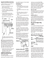
4. Referring to the drawing below, start the table
assembly onto the first set of bearings making sure
they locate properly in the machined track.
5. Slide the table across until the second set of bear-
ings contacts the end of the track. Insure proper
bearing alignment and slide the table the rest of the
way.
NOTE: THERE WILL BE A DEFINITE RESISTANCE
ENCOUNTERED WHEN FIRST ENGAGING THE SECOND SET OF BEARING. This is due to the pre-loaded
design in which the bearings actually squeeze the mating
track. It is important to be sure the bearings are aligned
with the machine track before using any force. When
properly aligned, a slight nudge is all that’s required to
urge the table over the second set of bearings.
6. Install the retainer bar using the two machine screws
provided. Make sure that the rubber bumper is
oriented properly. If in doubt, examine the
opposing end of the table assembly.
OPERATING INSTRUCTIONS
VERTICAL WHEEL POSITION
The vertical wheel position allows use of the calibrated
table and tool guide. Two tool angles can be simultane-
ously controlled. Tool clearance (or relief) can be adjusted
by setting the table elevation.
TO SET ELEVATION:
1. Slide table to the right.
2. Set the “pie-shaped” elevation scale to the desired
value (0 is perpendicular to the wheel) and tighten
the locking knob.
3. Slide the table to the left and rest it on the elevation
scale.
4. While the table is resting on the elevation scale
tighten the sliding knob to hold the desired
elevation.
5. Loosen the elevation scale locking knob so the scale
drops out of the way.
For very small tools, especially small inserts, the gap
between the table and the cutting wheel may be unhandy.
This is easily overcome by clamping a flat piece of sheet
metal onto the table so it barely clears the cutting wheel.
To insure proper elevation accuracy, the hinged surfaces
between the main motor housing and the table side arms
must be kept clean. Make sure that no metal particles or
other obstructions are stuck to the holding magnets or
their mating surfaces.
The tool guide is from 60° either side of 0. It needs no
explanation to use. The guide is easily removed for jobs
that need an unobstructed table. Note that the tool guide
can be removed without completely removing the top
knurled locking nut.
Angles greater than 60° can be obtained using a piece of
flat material approximately 2” square and 1/8” to 1/2”
thick. Place this square block along the tool guide and
rest the tool along the perpendicular edge. The desired
tool angle is now easily set considering the 90° offset.
TABLE OSCILLATION
A cautionary note concerning the 600 and 1200 grit
wheels; generally it is recommended that you refrain from
oscillation on these wheels as it is very easy to pinch a
tool between the wheel and the tool guide assembly,
causing the corner of the tool to jam the wheel and possibly groove it. Instead, try to use different areas of the
wheel from time to time for even wheel wear.
WHEEL FACE RUNOUT
To insure proper wheel trueness, make sure that the back
of the wheel and the spindle face are clean when mounting wheels. Small dirt particles can produce excessive
face runout.
HORIZONTAL WHEEL USE
The motor housing pivots away from the cutting wheel to
operate horizontally. This feature has many diverse uses.
Two of the more common uses include refinishing the
tops(or faces) of inserts and honing flat surfaces on tool
blanks. It is also useful in removing build-up from the top
edges of cutting tools.
Over-grind tool angles during
roughing
This is best illustrated in the drawing below. Only a small
area around the cutting edge is important during the
machining process, the rest is clearance. But this small
area is critical! By over grinding the tool angle the
machinist has only to finish a small cutting edge. This
saves time and wheels. The sketch is exaggerated to
show the concept.
In practice a couple of degrees difference is sufficient.
Always keep your cutting tools
sharp!
The table moves parallel to the cutting wheel to allow the
operator to utilize the entire wheel surface. The table can
be oscillated by the operator while grinding a tool: Modern
technology has made the Goodson wheel much tougher
and oscillation to extend wheel life is less important. If it is
convenient to oscillate, then do so, otherwise don’t worry!
As a cutting tool dulls, many things start to happen. Heat
increases rapidly. Surface finish deteriorates. Tolerances
vary. The reason many cutting edges break catastrophically is that they were used too long before resharpening.
This is especially true with high performance tools such
as carbide. In the long run, more frequent tool changes to
maintain clean cutting edges will pay off. Also, tools the
are resharpened before they are ruined require just a
quick “touch-up” rather than extensive rework or even
scrapping. As a general rule, the finer the finish on a cut-