1
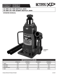
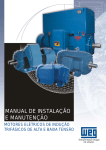
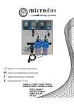
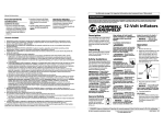
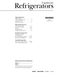
SPRING-ENGAGED
FAN DRIVE
REPAIR KIT
INSTALLATION INSTRUCTIONS
INSTRUCCIONES DE INSTALACIÓN
KIT DE REPARACION
TABLE OF CONTENTS
INTRODUCTION....................................................................2
General Information.........................................................2
PRIOR TO SERVICING.........................................................3
REMOVING THE FAN DRIVE................................................3
DRIVEMASTER PARTS........................................................4
Parts Identification...........................................................4
Repair Kits.......................................................................5
DriveMaster Seal Kit ....................................................5
DriveMaster Super Kit .................................................6
DriveMaster Friction Disc Kit .......................................7
DriveMaster Friction Liner Kit ..................................... 7
DriveMaster Bearing/Cartridge Kit................................7
DriveMaster Clutch Pack Kit.........................................8
DISASSEMBLING THE FAN DRIVE.....................................8
Tools Required.................................................................8
Disassembly.....................................................................8
Fan Mounting Disc Removal and Inspection................8
Spring Housing/Piston Assembly Removal..................9
Air Chamber Seals......................................................10
Sheave and Sheave Bearings....................................10
TORQUE SPECIFICATIONS...............................................11
REBUILDING THE FAN DRIVE...........................................11
Sheave Bearings........................................................ 11
Air Cartridge................................................................12
Sheave Replacement.................................................13
Spring Housing/Piston Assembly Reassembly...........13
Fan Mounting Disc Reassembly.................................15
REINSTALLING THE FAN DRIVE.......................................15
TROUBLESHOOTING.........................................................16
Warranty
For product specific warranty information, please visit the Horton online Literature Order Center at http://www.
hortonww.com or call Horton Customer Service at 1-800-621-1320.
INTRODUCTION
General Information
Horton uses the following special notices to give warning of possible safety related problems which could cause
serious injury and provide information to help prevent damage to equipment.
Danger is used to indicate the presence of a hazard which will cause severe personal injury, death, or
substantial property damage if the warning is ignored.
Warning is used to indicate the presence of a hazard which can cause severe personal injury, death,
or substantial property damage if the warning is ignored.
22748-J-0407
English
Caution is used to indicate the presence of a hazard which will or can cause minor personal injury or
property damage if the warning is ignored.
NOTE
Note is used to notify people of installation, operation, or maintenance information which is important
but not hazard related.
PRIOR TO SERVICING
You must follow your company safety practices, which should adhere to or be better than Federal or State
approved shop safety practices and procedures. Be sure that you read and understand all the procedures and
instructions before beginning work on this unit.
NOTE
Parts replacement and/or repair of your Horton DRIVEMASTER Fan Drive should be performed only
by the Horton Factory or an authorized Horton Distributor or Dealer to keep your warranty coverage
intact during the warranty period.
Before rebuilding your DRIVEMASTER Fan Drive, note the Fan Drive Service Part No., Date of Installation,
and Vehicle Mileage.
Part Number
Service Part No._ _______________________________
Installation Date_________________________________
Vehicle Mileage_________________________________
removing the fan drive
NOTE
The procedure for removing the Fan Drive varies from one vehicle to another. Refer to the vehicle’s
service manual for a detailed description of this process. In general, proceed as follows:
1.
Turn the vehicle ignition off, apply the vehicle’s parking brake, and block the vehicle’s wheels.
NOTE
Protect the radiator from possible damage from the fan during fan removal and fan drive installation.
2.
Remove the fan from the Fan Drive.
3.
Bleed the air from the vehicle’s reservoir and disconnect the air hose from the Fan Drive.
4.
Loosen or remove the drive belts.
NOTE
Because of the weight of the Fan Drive (ranging from 35-55 Lbs. [15.88-24.95 Kg]),
you may want to use a hoist for support during removal.
22748-J-0407
5. Remove the Fan Drive mounting bolts and lift the Fan Drive out of the engine compartment.
Fan
Drive
Grade 8
Mounting Bolts
Grade 8
Nuts
Steps 1-5
drivemaster parts
Parts Identification
ITEM
DESCRIPTION
1 Journal Bracket
21 Ball Bearings
3 Sheave
41 Bearing Nut
5 Air Chamber Cap
61 O-Ring Seal
91 Fan Mounting Disc/Studs
501 Spring Housing/Piston
171 Button Head Screws
22748-J-0407
QTY ITEM
1
2
1
1
1
1
1
1
8
18 201
442
221
231
241
281
512
551
1
1
2
Denotes Repair Kit item.
Not used on all Fan Drives.
DESCRIPTION
Air Chamber Seal
Face Seal
Bearing Spacers
Air Chamber Cap Retaining Ring
Air Cartridge Assembly
Air Cartridge Retaining Ring
Friction Liner
Jam Nut
Cage Nut (Used for repairs only)
QTY
1
1
1
1
1
1
1
1
-
English
Repair Kits
Horton offers several different ways to repair or rebuild your DriveMaster Fan Drive. If you’ve purchased a
PolarExtreme repair kit for applications requiring even greater torque, the repair procedures will be the same
as the standard repair kits.
DriveMaster Seal Kit
Install a Seal Kit if an air leak has developed inside of the DriveMaster Fan Drive. The Seal Kit consists of the
parts listed and described below:
Air Chamber Seal (#18): The air chamber seal forms an air seal between the air chamber and the spring housing/
piston assembly. The air chamber seal goes around the bottom half of the spring housing/piston assembly.
O-Ring (#6): The o-ring forms an air seal between the air chamber and the air chamber cap.
Air Cartridge (#23): The air cartridge fits inside the Journal shaft. Air pressure comes up through the center of
the shaft, into and through the air cartridge, and into the air chamber. The cartridge has a spring loaded carbon
tip that presses against the face seal and forms an air tight seal while the fan drive is spinning.
Face Seal (#20): The face seal screws into the center of the air cap and forms an air seal with the carbon tip
of the air cartridge.
Retaining Rings (#22, #24): There are two retaining rings in the seal kit. The smaller retaining ring is used to
hold the air cartridge inside the journal shaft. When installing this retaining ring, the beveled side must be facing
the air cartridge. The larger retaining ring is used to hold the air cap in place.
Button Head Screws (#17): The torx button head screws are used to attach the friction liner and the spring
housing to the sheave. Alternately and evenly tighten the screws to 80 in lbs torgue.
Cage Nut (#55): The cage nut is used to keep the spring housing/piston assembly together when removing from
the sheave. It maintains pressure on internal springs after the button head screws are removed.
T55 Torx Plus Bit (not pictured): The T55 torx plus bit is used to help remove the fan mounting disc from the
jack bolt.
O-Ring Lubricant (not pictured): Apply lubricant to the new air chamber cap o-ring and the air chamber seal
before installation.
22748-J-0407
DriveMaster Super Kit
Install a Super Kit if the bearings are running rough or if the DriveMaster Fan Drive needs to be completely rebuilt
due to excessive wear. The Super Kit consists of the parts listed and described below:
Spring Housing/Piston Assembly (#50): The spring housing/piston assembly is the internal mechanism that
engages and disengages the DriveMaster fan drive when air pressure is either removed or applied.
Fan Mounting Disc (#9): The fan mounting disc is the part that the fan is bolted on to. It is also the part that
contacts the friction liner when the fan drive is engaged. The fan mounting disc is screwed onto the jack bolt.
Check the fan mounting disc for blistering or damage.
Friction Liner (#28): The friction liner is attached to the sheave on top of the spring housing assembly.
Sheave Bearings (#2): Use a bearing press to remove old bearings and install new bearings into the center of
the sheave. The bearings are prelubricated and sealed. They also contain markings that need to be aligned for
proper installation (see sheave illustration Step 2A on page 14). If there are spacers in between the old bearings
that were removed, reuse those spacers by positioning them between the new bearings before installation. Do
Not remove the seals and attempt to lubricate the old or new bearings.
Bearing Nut (#4): The bearing nut is used to hold the sheave onto the journal shaft.
Air Chamber Seal (#18)
O-Ring (#6)
Air Cartridge (#23)
Face Seal (#20)
Retaining Rings (#22, #24)
Button Head Screws (#17)
Cage Nut (#55)
T55 Torx Plus Bit (not pictured)
O-Ring Lubricant (not pictured)
22748-J-0407
English
DriveMaster Friction Disc Kit
Install a Friction Disc kit if the fan mounting disc is damaged from blistering, excessive wear, or failure. The
Friction Disc kit consists of the parts listed below (descriptions on previous page):
Fan Mounting Disc (#9)
Friction Liner (#28)
Button Head Screws (#17)
Cage Nut (#55)
T55 Torx Plus Bit (not pictured)
DriveMaster Friction Liner Kit
Install a Friction Liner kit if the friction liner is worn. Check the fan mounting disc to make sure there is no
excessive wear. If damage is evident use the DriveMaster Friction Disc kit. The Liner kit consists of the parts
listed below (descriptions on previous page):
Friction Liner (#28)
Button Head Screws (#17)
Cage Nut (#55)
T55 Torx Plus Bit (not pictured)
DriveMaster Bearing/Cartridge Kit
Install a Bearing/Cartridge Kit if the sheave bearings are running rough inside of the DriveMaster Fan Drive. The
Bearing/Cartridge Kit consists of the parts listed below (descriptions on previous pages):
One Double
Row
Bearing
55
17
2
23
24
4
20
5
6
22
18
Two-Single
Row
Bearings
55
17
2
2
23
24
Sheave Bearings (#2)
Bearing Nut (#4)
O-Ring (#6)
Button Head Screws (#17)
Air Chamber Seal (#18)
Face Seal (#20)
Retaining Ring (#22)
Air Cartridge (#23)
Retaining Ring (#24)
Cage Nut (#55)
T55 Torx Plus Driver (not pictured)
O-Ring Lubricant (not pictured)
4
20
5
6
22
18
Bearing Spacers are not part of the kit because they can be reused.
22748-J-0407
DriveMaster Clutch Pack Kit
Install a Clutch Pack Kit if the DriveMaster Fan Drive needs to be completely rebuilt due to excessive wear. The
Clutch Pack Kit consists of the parts listed below (descriptions on previous pages):
18
17
50
55
Button head Screws (#17)
Air Chamber Seal (#18)
Spring Housing/Piston (#50)
Cage Nut (Used for Repair Only) (#55)
T55 Torx Plus Driver (not pictured)
O-Ring Lubricant (not pictured)
DISASSEMBLing the fan drive
Tools Required
•
•
•
•
•
•
2” Socket Wrench
T55 Torx Plus Bit (994352)
T27 Torx Bit
Pry Bar
Ring Pliers
Screwdrivers
Disassembly
Fan Mounting Disc Removal and Inspection
1.
Place the Fan Drive in a vise and clamp the Journal
Bracket tight.
Pry Bar
Torx Wrench
NOTE
Applying 90-120 PSI air pressure to the Fan Drive
air inlet. This will aid in removal of the FMFD.
2.
Loosen the Jack Bolt (left hand thread) by turning
it counter-clockwise using a T55 Torx Plus Bit.
Air Line
NOTE
Use caution when handling the prybar on the Fan
Mounting Disc. Permanent damage may occur if
not properly supported. Best results are achieved
with a flat blade tool like a Wonder Bar® or a prybar
that has a handle.
NOTE
In CCW rotation applications, a jam nut will be
installed over the threads of the jack bolt. This
nut must be removed (left hand thread) before
loosening the jack bolt.
22748-J-0407
Pry Bar
Placement
Steps 1-2
English
3.
Unscrew the Fan Mounting Disc from the Jack Bolt. Inspect the Fan Mounting Disc for wear or damage.
(See examples below)
Fan
Mounting
Disc
Jack Bolt
(left hand thread)
Step 3
Look for signs of damage or blistering
Fan Mounting Disc
Bad Condition
Fan Mounting Disc
Good Condition
Spring Housing/Piston Assembly Removal
4.
Hand-tighten the Cage Nut (from the Repair Kit)
onto the Jack Bolt (left hand thread) over the
Spring Housing. The Cage Nut will keep the Spring
Housing and Piston together as an assembly. It will
also maintain pressure on the internal Springs after
the Button Head Screws are removed.
Button
Head Screws
Friction Liner
Cage Nut
Spring
Housing/
Piston
Assembly
Remove air pressure from the unit before
proceeding to Step 5.
Failure to release air pressure may
result in serious personal injury.
Steps 4-5
Do not disassemble the Spring Housing. Personal
injury could occur.
5.
Remove the 8 Button Head Screws and the Friction
Liner using a T27 Torx Bit.
22748-J-0407
NOTE
If you are installing either a Friction Liner, Fan Disc Kit, or Clutch Pack Kit, skip to page 14, step
16.
6.
Remove the Spring Housing/Piston Assembly.
7.
Examine the inside of the Air Chamber for signs of
moisture and/or contaminants.
The Air Chamber should be clean and moisturefree (with the exception of the seal lubricant) . If
not, a problem may exist in the vehicle air system
and must be corrected before the Fan Drive is
reinstalled.
Spring Housing/
Piston Assembly
Air Chamber
Steps 6-7
Air Chamber Seals
Air Chamber Seal
Wear eye safety protection when removing
Retaining Ring to avoid serious injury.
8.
Remove the Air Chamber Cap Retaining Ring.
9.
Gently and evenly pry the Air Chamber Cap out of
the Sheave using two small screwdrivers placed
180° apart.
Air Chamber Cap
10. Remove the O-Ring Seal and Face Seal from the
Air Chamber Cap.
Face Seal
Retaining Ring
O-Ring Seal
11. Inspect the Face Seal for signs of wear. Wear
indicates that dirt may exist in the air system.
If dirt or oil exists in the air system, the air system
must be cleaned and dried before the Fan Drive is
reinstalled.
Steps 8-11
Sheave and Sheave Bearings
12. Remove the Bearing Nut from the Journal Bracket
using a 2” Socket Wrench.
Bearing Nut
Journal Bracket
Step 12
22748-J-0407
10
English
13. Slide the Sheave and bearing assembly off the
Journal Bracket.
Sheave
Journal Bracket
Step 13
NOTE
If you are only installing a Seal Kit proceed to page 12, step 3.
TORQUE SPECIFICATIONS
ITEM
DESCRIPTION
TIGHTENING TORQUE
4
Bearing Nut
130 Ft. Lbs. [176 N•m]
12
Jack Bolt (left hand thread)
100 Ft. Lbs. [136 N•m]
17
Button Head Screws
80 In. Lbs. [9 N•m]
20
Face Seal
75-100 In. Lbs. [8.5-11.5 N•m]
51
Jam Nut
120 Ft. Lbs. [163 N•m]
REBUILDING THE FAN DRIVE
Sheave Bearings
1.
Fully support the Sheave and press the Bearings
out of the Sheave.
NOTE
Some Models of the DRIVEMASTER Fan Drive
contain Bearing Spacers. Both Bearing Spacers
must be positioned BETWEEN the Sheave
Bearings when the Sheave Bearings are replaced.
All Bearings are prelubricated and sealed. DO
NOT remove the seals to lubricate the Bearings.
11
SUPPORT
BEARINGS
PRESS
TO
REMOVE
SUPPORT
Step 1
22748-J-0407
2.
Fully supporting the Sheave, press the new Sheave
Bearings (or single bearing) into place, noting the
position of the lip inside the Sheave.
See Figures 2A, 2B, 2C.
NOTE
Some DRIVEMASTER models utilize a single (one
piece) Sheave Bearing. Repair with Kit #994353.
NOTE
When installing new bearings, you must press on
the outer diameter ring of the bearing set to avoid
damaging the bearing during installation.
Align the chevron markings on the bearings to form an
arrow. The arrow may point in either direction.
Press on outer
bearing race
when installing
new bearings
Step 2A
NOTE
POSITION OF LIP
Bearings
(or single bearing)
Press
on inner
bearing
race
when
removing
old
bearing
SUPPORT
SUPPORT
Sheave
Bearings Spacers
PRESS
Step 2B
Step 2C
Air Cartridge
Retaining
Ring
Wear eye safety protection when removing
Retaining Ring to avoid serious injury.
3.
Remove the Retaining Ring.
4.
Remove the Air Cartridge Assembly. Clean the
Journal Bracket bore if necessary.
Step 3
5.
Apply O-Ring lubricant to the outside O-Rings of
the new Air Cartridge Assembly.
6.
Install the new Air Cartridge Assembly into the
Journal Bracket.
7.
Reinstall the Retaining Ring.
Float Seal
Tip
Step 4
22748-J-0407
12
Air Cartridge
Assembly
~
Espanol
O-Rings
The Retaining Ring must be fully seated in the
retaining ring groove to keep the Air Cartridge
Assembly from moving. Also, the Retaining Ring
is beveled. The curved side must be installed
facing the Cartridge.
The curve faces the
Cartridge
Retaining Ring
Step 5
Sheave Replacement
8.
Slide the Sheave onto the Journal Bracket.
9.
Replace and tighten the Bearing Nut to 130 Ft. Lbs. [170 N•m] torque. Be sure that the Bearing Nut hex
is facing up (see detail below).
Sheave
Journal
Bracket
Step 8
Bearing
Nut
(Hex faces up)
Bearing Nut Detail
Hex faces up
Relief points down
toward Journal
Bracket and Bearings
Step 9
Spring Housing/Piston Assembly Reassembly
Use extreme care when reassembling the Air Chamber components to avoid damage to the O-Ring
and Air Chamber Seal.
10. Using a clean/dry cloth, clean both the Float Seal
Tip (see Air Cartridge illustration, Step 4) of the
Air Cartridge Assembly as well as the Face Seal
of the Air Chamber Cap. Use care not to scratch
seal surfaces.
NOTE
The new Face Seal is assembled with an O-ring. If
the old Face Seal does not have an O-ring, remove
it from the new Face Seal and apply thread sealant
(Loctite® 511 or similar) to the Face Seal threads.
Air Chamber Cap
Retaining Ring
11. Assemble the Air Chamber Cap and Face Seal.
Lubricate the O-ring Seal with the fresh lubricant
supplied in the kit and install it on the Air Chamber
Cap.
12. Carefully set the Air Chamber Cap into the
Sheave and install the Retaining Ring.
Sheave
Steps 11-12
13
22748-J-0407
13. Lubricate the Air Chamber Seal and contact
surfaces with the fresh lubricant supplied in the
kit.
NOTE
The entire tube of O-Ring lubricant should be
used when lubricating the new seals and contact
surfaces of the Sheave and Spring Housing/Piston
Assembly.
Do not apply grease beyond Seal contact surface
as it will cause improper Fan Drive function.
14. Install the Air Chamber Seal into the Sheave as
shown. Be sure the Seal is evenly seated against
the side and bottom of the groove surfaces.
15. Carefully set the new Spring Housing/Piston
Assembly from the Repair Kit into position. Gently
rotate to align the mounting holes in the assembly
with the Sheave.
“V” of Seal
faces down into
Sheave
Do not apply
grease beyond
these areas.
Sheave
(cross-section)
Steps 13-14
Spring Housing/
Piston Assembly
Air Chamber
Seal
16. Set the new Friction Liner (from kit) into place.
Handle the Friction Liner by the edges to avoid
contamination.
17. Alternately and evenly tighten the 8 Button Head
Screws to 80 In. Lbs. [9 N•m] torque.
Steps 14-15
To avoid personal injury, make sure the Button
Head Screws are properly tightened to the specified
torque before applying air pressure - 80 In. Lbs. [9
N•m].
Button
Head Screws
Friction Liner
Cage Nut
Spring Housing/
Piston Assembly
Steps 16-17
22748-J-0407
14
Air Chamber Seal Detail
(inside of Sheave)
Seat Seal
evenly against
side and
bottom groove
surfaces.
English
Fan Mounting Disc Reassembly
18. Apply a minimum of 90 lbs. PSI of clean air to the
air inlet.
Fan
Mounting
Disc
NOTE
Air must be applied to the air chamber to allow for
easy removal of the Cage Nut and to ensure proper
torque is applied to the Jack Bolt.
Jack Bolt
(left hand
thread)
19. Remove the Cage Nut from the Spring Housing/
Piston Assembly.
20. Install the new Fan Mounting Disc (from kit) if
applicable.
Do not disassemble the Spring Housing.
Personal injury could occur.
Steps 18-19
21. Tighten the Jack Bolt (left hand thread) to 100 Ft.
Lbs. [136 N•m] torque.
22. If a jam nut was present, apply Loctite® 204 (or
equivalent) to the threads, reinstall over the jack
bolt (left hand thread) and tighten to 120 Ft. lbs
[163 N•m] torque.
23. Actuate the DriveMaster and check for proper
engagement and disengagement of the Fan
Mounting Disc. Check for air leaks at the bleed hole
and around the Spring Housing/Piston Assembly.
If a problem exists, it must be corrected prior to
mounting the Fan Drive onto the vehicle. If the
problem is not corrected, the Fan Drive will fail
prematurely.
Steps 20-22
reinstalling the fan drive
On the workbench, apply 90 psi [6.21 bar] clean air pressure and check the
Fan Drive for air leaks.
1.
Be sure the vehicle ignition is off, the vehicle’s parking brake is applied, and the vehicle’s wheels are
blocked.
NOTE
Protect the radiator from possible damage from the fan
during fan removal and fan drive installation.
2.
Clean the Fan Drive mounting surface on the engine.
NOTE
Most engines have multiple mounting locations.
Be sure to use the correct holes for the application.
15
22748-J-0407
3.
Bolt the Fan Drive to the engine. Use flat washers on each manufacturer’s approved bolt or studs - DO
NOT use lock washers. Tighten the mounting bolts to the vehicle manufacturer’s specifications.
Correct belt adjustment and alignment is necessary for all belt driven components to assure longevity
of component life. Over tightening of belts will shorten bearing life. Loose belts will cause excessive
belt wear and shorten bearing life. Consult the equipment manufacturer and/or engine manufacturer
specifications for proper belt adjustment.
4.
Replace and tighten the belts to manufacturer’s specification.
The maximum fan diameter is 32’’.
If a larger fan diameter is required, contact Horton at 1-800-621-1320.
5.
Check the fan for cracks or missing weights; then, remount the fan on the Fan Drive. Tighten the bolts
and/or nuts to the vehicle manufacturer’s specifications.
6.
Start the engine and let the air pressure build to at least 90 psi [6.21 bar].
Turn off the engine.
7.
Manually engage and disengage the Fan Drive by opening and closing the electrical circuit going to the
solenoid valve. For a normally-open electrical system, use a jumper across a sensor. For a normally-closed
electrical system, open the circuit by disconnecting a sensor wire. With the Fan Drive engaged, recheck
the entire system for air leaks, or activate the manual override switch (if equipped).
TROUBLESHOOTING
PROBLEM
I. Air leaking from Fan Drive
bleed hole
PROBABLE CAUSE
1. Bad seals or air cartridge.
SOLUTION
1. Install Repair Kit.
Bleed Hole
Journal Bracket
II. Premature Friction
Lining failure
1. Obstructed fan.
1. Loose shroud, bent fan,
torn engine mounts, etc.
2. Low air pressure to Fan
Drive.
2 a. Restricted air line.
b. Restricted Solenoid Valve.
c. Low system air pressure.
d. System air leak.
22748-J-0407
16
1. Find and remove
obstruction, repair or
replace damaged parts.
Install Repair Kit.
2. a. Replace air line. Install Repair Kit.
b. Replace Solenoid Valve. Install Repair Kit.
c. Repair system.
Install Repair Kit.
d. Repair leak.
Install Repair Kit.
English
TROUBLESHOOTING
PROBLEM
3. Excessive cycling.
PROBABLE CAUSE
3. a. A/C freon overcharge.
b.
c.
d.
A/C pressure switch setting too low.
Poor ground or wire
connection.
Improper temperature
control setting.
SOLUTION
3. a. Check and adjust to specifications.
b. Check A/C pressure switch.
c. Check electrical connections.
d. Check temperature setting of all controls.
Thermal Switch setting should engage the Fan Drive 10oF higher than the full open temperature of the thermostat.
e. Check ECM.
e. Faulty ECM.
f. Faulty Thermal Switch.
g. Restriction in front of
radiator blocking air flow.
h. Faulty Air-Temp Switch.
f.
g.
h.
Replace the Thermal Switch.
Check for proper shutter operation, winter front or other restriction in or in front of the radiator.
Replace the Air-Temp Switch.
Air Problem
1. Solenoid Valve not exhausting
or engaging properly.
III. Fan Drive fails to
engage/disengage
1. Check for plugged exhaust/
intake port on the Solenoid
Valve. Clean or replace the
Solenoid Valve.
Electrical Problem
1. Open/shorted circuit.
1. Check electrical connections.
2. Improperly wired.
2. Check wiring according to
diagram.
3. Thermal Switch incorrect for
application.
3. Check Thermal Switch
application. Replace if wrong
or defective.
4. Failed Solenoid Valve.
4. Replace the Solenoid Valve.
Air Problem
1. Air line restricted.
1. Check air line from solenoid
to Fan Drive for kinks or
obstructions.
2. Solenoid Valve defective.
2. Replace the Solenoid Valve.
Check to see if air exhaust is
restricted.
17
22748-J-0407
PROBLEM
III. Fan Drive fails to
engage/disengage (con’t)
IV.Fan Drive cycles
frequently
V. Fan Drive engaged, engine running hot.
22748-J-0407
PROBABLE CAUSE
SOLUTION
Piston will not actuate
1. Piston seized due to
contamination or dry seals.
1. Clean the air supply and
install a Rebuild Kit.
Electrical Problem
1. Poor ground wire connection.
1. Check electrical connections.
2. Improper temperature control
settings.
2. Check temperature setting
of all controls. Thermal
Switch should engage the Fan
Drive 10o F higher than the
full open temperature of the
thermostat.
3. A/C Pressure Switch setting
too low.
3. Check A/C Pressure Switch. Use higher switch.
4. Restriction in front of radiator,
blocking air flow.
4. Check shutter operation,
winter fronts, or obstruction in
front of radiator.
5. Faulty Thermal Switch.
5. Replace the Thermal Switch.
6. Faulty Air-Temp Switch.
6. Replace the Air-Temp Switch.
7. Vehicle Coolant level too low.
7. Fill to manufacturer’s
recommended level.
1. Restriction in front of radiator.
1. Make sure nothing is
obstructing the air flow
through the radiator.
2. Fan capacity not large
enough.
3. Problem in cooling system.
2. Refer to specifications.
18
3. Refer to engine manual.
~
Espanol
TABLA DE CONTENIDOS
INTRODUCCIÓN..................................................................20
Información General......................................................20
INFORMACIÓN PREVIA.....................................................20
DESMONTANDO EL IMPULSOR DE VENTILADOR.........21
PARTES DEL DRIVEMASTER............................................22
Identificación de partes..................................................22
Kits de reparación..........................................................23
DriveMaster Kit de sellado . ......................................23
DriveMaster Super Kit ..............................................24
DriveMaster Disco de Fricción . ................................24
DriveMaster Pastas de Fricción . ..............................25
Kit de baleros y cartucho de aire del DriveMaster......25
Paquete del clutch DriveMaster . ...............................26
DESENSAMBLE DEL DRIVEMASTER...............................26
Herramientas requeridas...............................................26
Desensamble.................................................................26
Desmontaje del disco de fricción e inspección...........26
Desmontaje de la carcaza de resortes.......................27
Sellos de la cámara de aire........................................28
Polea y sus baleros....................................................28
ESPECIFICACIONES DE PAR............................................29
RECONSTRUCCIÓN DEL DRIVEMASTER........................29
Baleros de la polea.....................................................29
Cartucho de aire.........................................................30
Montaje de la polea....................................................30
Montaje de la Carcaza de resortes.............................31
Montaje del disco de fricción......................................32
MONTAJE DEL DRIVEMASTER.........................................33
PROBLEMAS Y SOLUCIONES..........................................34
Garantia
Para informacion especifica de Garantia del Producto, por favor visite el Centro de
Literatura en linea, en http://www.hortonww.com O llame a Servicio al Coliente a
1-800-621-1320.
19
22748-J-0407
INTRODUCCIÓN
Información General
Horton utiliza los siguientes avisos especiales para advertir sobre posibles problemas de seguridad que podrían
producir heridas de gravedad y para proporcionar información para prevenir daños al equipo.
PELIGRO
Se utiliza para indicar la presencia de un peligro que podría producir heridas graves, mortales ó
daños serios a la propiedad.
ADVERTENCIA
Se utiliza para indicar la presencia de un peligro que podría producir heridas graves, mortales ó
daños serios a la propiedad.
PRECAUCION
Se utiliza para indicar la presencia de un peligro que puede ó podría producir heridas leves, ó daños
a la propiedad.
NOTA
Se utiliza para indicar información importante relativa a la instalación, el funcionamiento ó el
mantenimiento, pero que no implica riesgos personales ni a la propiedad.
INFORMACIÓN PREVIA
Se deben seguir las normas de seguridad de la compañía, las cuales deben ser iguales o mejores con respecto
a las normas de seguridad establecidas por el gobierno federal y estatal para talleres de reparación. Se debe
familiarizar con todas las instrucciones y procedimientos de instalación antes de comenzar a trabajar con esta
unidad.
NOTA
El cambio de componentes y/o la reparación de su DriveMaster de Horton debe llevarse a cabo en
la fabrica de Horton ó con un Distribuidor Autorizado ó Agencia del Fabricante del vehículo para
mantener la cobertura de la Garantía durante el período de la misma.
Antes de reparar su DriveMaster, tome nota del Número de parte del componente, fecha de instalación y
kilometraje del vehículo.
Numero De Parte
No. Parte del componente ____________
Fecha de Instalación ____________
Kilometraje del vehículo _____________
22748-J-0407
20
~
Espanol
DEMONTAJE DEL IMPULSOR DE VENTILADOR
NOTA
El procedimiento de desmontaje del DriveMaster varía de un vehículo a otro . Refiérase al manual
de Servicio para una detallada descripción del proceso. En general proceda como se indica a
continuación:
1. Apague el motor, aplique los frenos de estacionamiento y bloquee las ruedas del vehículo.
NOTA
Proteja el radiador de posibles daños durante el desmontaje y montaje del DriveMaster.
2. Desmonte el ventilador del DriveMaster
3. Purgue el aire del tanque de almacenamiento del vehículo y desconecte la manguera de aire del DriveMaster.
4. Afloje y desmonte las bandas.
NOTA
Debido al peso del DriveMaster 15.88 a 24.95 kg se recomienda el uso de un malacate para la
maniobra.
5.
Remueva los tornillos del soporte del DriveMaster y levántelo para sacarlo del compartimiento del motor.
Impulsor de
ventilador
Tornillos de
montaje grado 8
Tuercas
grado 8
Pasos 1 - 5
21
22748-J-0407
PARTES DEL DriveMaster
Identificación de Partes
ART
DESCRIPCIÓN
1 Soporte con flecha
21 Baleros de bolas
3 Polea
41 Tuerca de baleros
5 Tapón de cámara de aire
61 Aro sello (O-ring) 91 Disco de fricción (birlos)
501 Carcaza de resortes (pistón)
171 Tornillos Torx
CANT ART
1
2
1
1
1
1
1
1
8
181
201
442
221
231
241
281
512
551
Artículo del kit de reparación
2
No se utiliza en todos los DriveMaster
1
22748-J-0407
22
DESCRIPCIÓN
CANT
Sello de la cámara de aire
Sello Frontal
Espaciador de baleros
Retén del tapón cámara aire
Cartucho aire ensamblado
Retén del cartucho de aire
Pastas de fricción
Contratuerca
Tuerca circular (solo para reparaciones)
1
1
1
1
1
1
1
1
-
~
Espanol
Kits de Reparación
Horton ofrece varias maneras de reparar su DriveMaster. Si usted ha comprado un kit de reparación PolarExtreme
para aplicaciones que requieren de un par mayor, el procedimiento de reparación será el mismo que se sigue
para un kit de reparación estándar.
DriveMaster Kit de sellado
Instale un kit de sellado, si se ha desarrollado una fuga de aire en el interior del DriveMaster. El kit de sellado
contiene los siguientes componentes:
Sello de la cámara de aire (#18): El sello de la cámara de aire forma el sello de aire entre la carcaza de resortes
y la cámara de aire. Este sello se coloca alrededor y en la parte inferior de la carcaza de resortes.
Aro sello (O-ring #6): El O-ring forma el sello de aire entre la cámara y el tapón de la cámara.
Cartucho de aire (# 23): El cartucho de aire se aloja en el barreno de la flecha del soporte. La presión de aire
pasa por el centro del cartucho a la cámara de aire. El cartucho tiene una punta flotante de carbón que se
presiona contra el sello frontal y forma un sello perfecto de aire mientras el DriveMaster gira.
Sello frontal (# 20): El sello frontal se atornilla en el centro del tapón de la cámara de aire y forma el sello de
aire con la punta de carbón del cartucho de aire.
Anillos retén (#22, # 24): Hay dos anillos retén en el kit. El pequeño se utiliza para detener el cartucho de aire
dentro de la flecha. Cuando instale este anillo asegúrese que la parte curva vaya hacia el cartucho de aire. El
grande se utiliza para asegurar el tapón de la cámara en su lugar.
Tornillos Torx (# 17): Los tornillos Torx se utilizan para fijar las pastas de fricción y la carcaza de resortes a
la polea. Apriete estos tornillos siguiendo un patrón de estrella a 80 lbs pulg de par.
Tuerca Circular (# 55): La tuerca circular se emplea para mantener la carcaza de resortes ensamblada cuando
se desmonta de la polea. Mantiene la presión de los resortes internos después que los tornillos Torx han sido
retirados.
Herramienta Torx T55 (no se muestra): Se utiliza para desmontar el disco de fricción del tornillo central.
Lubricante para O-ring (no se muestra): Aplique el lubricante al nuevo O-ring del tapón de la cámara de aire
y al sello de la cámara de aire antes de instalarse.
23
22748-J-0407
DriveMaster Super Kit
Instale un Super Kit si los baleros producen ruido ó si el DriveMaster necesita ser completamente reparado
debido a desgaste excesivo. El Super Kit consiste en las partes que se describen a continuación:
Carcaza de resortes/pistón ensamblado (# 50): La carcaza de
resortes es un mecanismo interno que embraga y desembraga al
DriveMaster cuando la prsion de aire es removida ó aplicada.
Disco de Fricción ( # 9): El disco de fricción es la parte donde
se fija el ventilador y también la parte donde las pastas de fricción
hacen contacto cuando se embraga el DriveMaster. El disco de
fricción se atornilla al tornillo central. Revise que el disco de
fricción no muestre desprendimiento de material ó daño.
Pastas de fricción (# 28): Las pastas de fricción se fijan a la
polea encima de la carcaza de resortes.
Baleros de la polea (# 2): Utilice una prensa para desmontar los
baleros usados e instalar los nuevos en la flecha del soporte. Los
baleros son prelubricados y sellados, también están marcados, de
manera que necesitan alinearse para instalarse apropiadamente
(vea la ilustración 2A, página 34). Si existe un espaciador entre
ellos, vuelva a utilizar este entre los nuevos al momento de instalarse. No remueva los sellos e intente lubricar
los baleros nuevos ó usados.
Tuerca de baleros (# 4): Esta se utiliza para mantener la polea en la flecha del soporte.
Sello de la cámara de aire (# 18)
Aro sello O-ring (# 6)
Cartucho de aire (# 23)
Sello frontal (# 20)
Anillos retén (# 22, # 24)
Tornillos Torx (# 17)
Tuerca Circular (# 55)
Herramienta Torx T55 (no se muestra)
Lubricante para O-ring (no se muestra)
DriveMaster Kit de Disco de fricción
Instale un kit de Disco de fricción si el disco de fricción está dañado con pérdida de material o desgaste excesivo.
El kit de disco de fricción contiene las partes que se describen a continuación:
Disco de fricción (# 9)
Pastas de fricción (# 28)
Tornillos Torx (# 17)
Tuerca Circular (# 55)
Herramienta Torx T55 (no se muestra)
22748-J-0407
24
~
Espanol
DriveMaster Kit de pastas de fricción
Instale un kit de pastas de fricción cuando las pastas están gastadas. Revise el disco de fricción y asegúrese
que no muestra desgaste excesivo. Si hay daño evidente utilice un kit de disco de fricción. El kit de pastas de
fricción contiene los componentes que se describen a continuación:
Pastas de fricción (# 28)
Tornillos Torx (# 17)
Tuerca Circular (# 55)
Herramienta Torx T55 (no se muestra)
Kit de baleros y cartucho de aire del DriveMaster
Instale un kit de baleros y cartucho de aire, si los baleros de la polea del DriveMaster hacen ruido al girar. El
kit de baleros y cartucho de aire contiene las partes listadas abajo (descripciones en páginas anteriores):
Un balero de doble hilera de bolas
Dos baleros de una
hilera de bolas
55
55
17
17
2
2
2
23
23
24
24
4
4
20
20
5
5
6
6
22
22
18
18
Baleros de la polea (#2)
Tuerca de baleros (#4)
Aro sello (#6)
Tornillos cabeza de gota (#17)
Sello de la cámara de aire (# 18)
Sello frontal (#20)
Anillo reten (#22)
Cartucho de aire (#23)
Anillo reten (#24)
Tuerca moleteada (#55)
Llave Torx T55 (no ilustrada)
Lubricante para aro sellos (no ilustrada)
Los espaciadores de baleros no están incluidos en el kit, porque pueden reutilizarse los anteriores.
25
22748-J-0407
Paquete del clutch DriveMaster
Instale un paquete del clutch DriveMaster, si el DriveMaster requiere ser completamente reconstruido debido
a un desgaste excesivo. El paquete del clutch contiene las partes listadas abajo (descripcion en páginas
anteriores)
18
17
50
55
Tornillos cabeza de gota (#17)
Sello de la cámara de aire (#18)
Carcaza de resortes/Pistón (#50)
Tuerca moleteada (#55)
Llave Torx T55 (no ilustrada)
Lubricante para aro sellos (no ilustrada)
DESENSAMBLE DEL DriveMaster
Herramientas Requeridas
·
·
·
·
·
·
Dado de 2”
Herramienta Torx T55 (994352)
Herramienta Torx T27
Barra plana
Pinzas para anillo retén
Desarmadores
Desensamble
Desmontaje e inspección del disco de fricción
1. Coloque el DriveMaster en un tornillo de banco y
sujételo por el soporte.
NOTA
Aplique una presión de aire de 90 – 120 PSI al
DriveMaster. Esto ayudará al desmontaje del disco
de fricción.
Barra plana
Herramienta
Torx
2. Afloje el tornillo central (rosca izquierda) girando en
el sentido contrario al reloj empleando la herramienta
Torx T55.
NOTA
Tenga cuidado cuando maneje la barra plana al
desmontar el disco de fricción. Puede producirse
daño si no se soporta adecuadamente. Se obtienen
mejores resultados si se utiliza una herramienta
como la “Wonder bar”® ó una barra con maneral.
NOTA
En aplicaciones de rotación en sentido contrario
a las manecillas del reloj, se instalará una
contratuerca en el tornillo central. Esta tuerca debe
removerse (rosca izquierda) antes de aflojar el
tornillo central.
22748-J-0407
26
Línea de aire
Colocación de
La barra plana
Pasos 1 - 2
3.
~
Espanol
Desatornille el disco de fricción del tornillo central. Revise que el disco de fricción este libre de marcas de
desgaste. (Ejemplos se muestran en las fotografías abajo.)
Disco
de fricción
Tornillo central
(rosca izq.)
Paso 3
Busque signos de desgaste o material desprendido.
Disco de fricción en malas condiciones
Disco de fricción en buenas condiciones
Desmontaje de la Carcaza de resortes/pistón ensamblado
4.
Apriete con la mano la tuerca circular (que viene
en el kit) en el tornillo central (rosca izq.) sobre
la carcaza de resortes. Esta tuerca mantiene a
la carcaza de resortes y al pistón juntos como un
ensamble. También mantiene la presión de los
resortes internos después que se han retirado los
tornillos Torx.
Tornillos Torx
Pastas de
fricción
Tuerca circular
La carcaza de
resortes
ADVERTENCIA
Retire la presión de aire antes de proceder con
el paso 6.
PELIGRO
NO RETIRAR LA PRESION DE AIRE PUEDE
OCASIONAR DANOS PERSONALES SEVEROS.
ADVERTENCIA
Pasos 4 - 5
No desensamble la carcaza de resortes. Daños
personales pueden ocurrir.
5.
Retire los 8 tornillos Torx y las pastas de fricción
utilizando la herramienta Torx T27.
27
22748-J-0407
NOTA
Si usted está instalando ya sea las Pastas de fricción, el disco de fricción, ó paqueta del clutch
DriveMaster, vea la página 32, paso 16.
6.
Desmonte la carcaza de resortes/pistón
ensamblado.
Carcaza de
resortes (pistón)
7.
Examine el interior de la cámara de aire y
busque signos de humedad ó contaminantes.
Cámara de aire
ADVERTENCIA
La cámara de aire debe estar limpia y libre de
humedad, solamente debe existir el lubricante
del sello. Si no es así existe un problema en el
sistema de aire del vehículo, el cual debe ser
corregido antes de volver a montar el DriveMaster.
Pasos 6 - 7
Sellos de la Camara de Aire
ADVERTENCIA
Debe utilizar lentes de seguridad cuando remueva
anillos retén para evitar serios daños.
Sello de la cámara
de aire
8. Retire el anillo retén del tapón de la cámara de aire.
Anillo retén
Aro sello
(O-ring)
9. Suavemente retire de su sitio el tapón de la cámara de aire, utilizando para ello dos desarmadores pequeños colocándolos a 180°.
Tapón de la cámara
de aire
Sello frontal
10. Retire el sello frontal y el O-ring del tapón de la cámara de aire.
11. Inspeccione el sello frontal busque signos de desgaste. Si hay desgaste significa que hay contaminantes en el sistema de aire del vehículo.
Pasos 8 – 11
PRECAUCION
Si hay contaminante o aceite en el sistema de aire,
éste debe limpiarse y secarse antes de instalar
nuevamente el DriveMaster.
Polea y Sus Baleros
12. Quite la tuerca de baleros empleando un dado de 2”.
Tuerca de
baleros
Soporte
Paso 12
22748-J-0407
28
13. Desmonte la polea con sus baleros de la flecha del
soporte.
~
Espanol
Polea
Soporte
NOTA
Si está instalando solamente el kit de sellado pase
a la pág. 30 paso 3.
Paso 13
ESPECIFICACIONES DE PAR
ART
DESCRIPCION
PAR DE APRIETE
4
Tuerca de baleros
176 N•m (130 ft lbs)
12
Tornillo central(rosca izquierda)
136 N•m (100 ft lbs)
17
Tornillos Torx
9 N•m (80 in lbs)
20
Sello frontal
8.5 – 11.5 N•m (75-100 in lbs)
51
Contratuerca
163 N•m (120 Ft-lbs)
RECONSTRUCCION DEL DRIVEMASTER
Baleros de la Polea
1. Soporte completamente la polea y extraiga los baleros.
NOTA
Algunos modelos del DriveMaster tienen
separadores entre los baleros. Estos espaciadores
deben colocarse con los baleros nuevos.
SOPORTE
PRESIONE
PARA
EXTRAER
Baleros
SOPORTE
Todos los baleros son sellados y prelubricados.
No quite los sellos para lubricar los baleros.
Paso 1
2. Soporte completamente la polea e introduzca los nuevos baleros (ó balero único) en la polea. Ver figuras 2A, 2B, 2C.
NOTA
Algunos DriveMaster utilizan solamente un balero.
NOTA
Cuando instale los nuevos baleros, se debe hacer
la presión solo en la pista exterior, para evitar
daño a los mismos.
29
Alinie las marcas de los baleros formando una flecha,
esta puede apuntar en cualquier dirección.
Presione
en la pista
exterior para
insertar los
baleros
Paso 2A
Presione
en la
pista
interior
para
extraer
los
baleros
usados
22748-J-0407
NOTE LA POSICION
DEL LABIO
SOPORTE
Baleros
(ó un solo balero)
SOPORTE
Polea
PRESIONE
Separador de baleros
Paso 2B
Paso 2C
Cartucho de aire
Anillo retén
ADVERTENCIA
Use lentes de seguridad cuando desmonte anillos
retén, para evitar daños personales.
3. Desmonte el anillo retén.
Paso 3
4. Desmonte el cartucho de aire. Limpie el barreno de la flecha si es necesario.
5. Aplique lubricante en el exterior de los O-ring del nuevo cartucho.
Punta de
carbón
flotante
6. Inserte el nuevo cartucho en el barreno de la flecha.
7. Reinstale el anillo retén.
Paso 4
Cartucho de aire
O-Rings
PRECAUCION
El anillo retén debe asentar en la ranura para
mantener el cartucho en su posición.
También el anillo retén tiene curvatura que va
hacia el cartucho.
Curva hacia el
cartucho
Paso 5
Anillo retén
Montaje de la Polea
8.
Deslice la polea en la flecha del soporte.
9.
Coloque y apriete la tuerca de baleros a 170 N•m (130 ft lbs) de par. Asegúrese que el hexágono de la tuerca está hacia arriba (ver detalle).
Polea
Soporte con
flecha
Paso 8
22748-J-0407
Tuerca de
baleros
Hexágono
hacia arriba
Paso 9
30
Detalle de la tuerca de
baleros
Cara hexagonal hacia
arriba
Alto relieve hacia
abajo, contra los
baleros.
~
Espanol
Montaje de Carcaza de Resortes
PRECAUCION
Tenga mucho cuidado al ensamblar los componentes de la cámara de aire para evitar dañar el O-ring
y el sello de la cámara.
10. Utilizando un trapo limpio y seco, limpie tanto la punta flotante de carbón como el sello frontal, tenga cuidado de no rayar las superficies de contacto.
Tapón de la cámara
de
aire
Anillo retén
NOTA
El nuevo sello frontal tiene un O-ring. Si el anterior
no tiene este O-ring, quitelo y aplique sellador
a la rosca (Loctite 511 ó similar) del nuevo sello
frontal.
11. Ensamble el sello frontal en el tapón de la cámara de aire. Lubrique el O-ring y móntelo en el tapón de la cámara de aire.
12. Con mucho cuidado coloque el tapón de la cámara de aire en la polea e instale el anillo retén.
13. Lubrique el sello de la cámara de aire y las superficies de contacto con el lubricante que se surte en el kit.
NOTA
Todo el lubricante que viene en el tubo debe
usarse para lubricar los sellos y las superficies de
contacto de la polea y la carcaza de resortes.
Polea
Pasos 11-12
Labios V del sello
Van hacia abajo
No aplique grasa
ademas de estas
areas.
Polea
(Sección
transversal)
Detalle del sello
de la cámara (Dentro de
la polea).
Asiente el sello
contra
paredes
lateral y fondo.
Pasos 13-14
PRECAUCION
No aplique grasa mas alla de los sellos y las
superficies de contacto, ya que puede ocasionar
un mal funcionamiento.
14. Instale el sello de la cámara de aire en la polea como se muestra. Asegúrese que el sello asienta perfectamente tanto en la pared lateral como la del fondo.
Carcaza de
resortes/
Pistón
ensamblado
Sello de cámara
De aire
15. Cuidadosamente asiente la carcaza de resortes en su posición. Gire suavemente para alinearla con los barrenos de la polea.
Pasos14-15
31
22748-J-0407
16. Coloque las nuevas pastas de fricción en su lugar. Maneje las pastas tomándolas por las aristas para evitar contaminación.
Tornillos Torx
17. Apriete los tornillos 8 Torx en patrón de estrella, a 9 N•m (80 in lbs) de par.
Pastas de
fricción
Tuerca
circular
ADVERTENCIA
Para evitar daños personales asegúrese que los
tornillos Torx estén apretados al par especificado
antes de aplicar la presión de aire.
Carcaza de
resortes
Pasos 16 - 17
Montaje del disco de fricción
18. Aplique una presión mínima de aire de 90 PSI en la entrada de aire del DriveMaster
NOTA
El aire debe aplicarse a la cámara para facilitar el
desmontaje de la tuerca circular y asegurar el par
de apriete del tornillo central.
Disco de
fricción
19. Remueva la tuerca circular de la carcaza de resortes.
Tornillo
central
(rosca izq.)
20. Instale el nuevo disco de fricción (que viene en el kit) si aplica.
21. Apriete el tornillo central (rosca izquierda) a 136 N•m (100 ft lbs) de par.
Pasos 18 – 19
22. Si había una contratuerca, aplique Loctite® 204 (ó equivalente)a la rosca y rosquela en el tornillo central (rosca izquierda) apretando a un par de 163 N•m, (120 lbs pie).
23.Active el DriveMaster y verifique que el
disco de fricción embrague y desembrague
apropiadamente. También verifique que no
existan fugas de aire por el barreno de sangrado y
alrededor de la carcaza de resortes.
PRECAUCION
Si existe algún problema, debe corregirse antes
de montar el DriveMaster en el vehículo. Si no
se corrige el problema, el DriveMaster fallará
prematuramente.
22748-J-0407
Pasos 20-22
32
~
Espanol
MONTAJE DEL DriveMaster
ADVERTENCIA
En el banco de trabajo aplique una presión de aire 6.21 bar (90 PSI) y verifique que no existan
fugas en el DriveMaster.
1. Asegúrese que el interruptor de ignición esté en apagado, que los frenos de estacionamiento están aplicados y que las ruedas del vehículo están bloqueadas.
NOTA
Proteja el radiador de posibles daños durante la instalación del DriveMaster.
2. Limpie la superficie del motor donde se montará el DriveMaster.
NOTA
La mayoría de los motores tienen barrenos multiples para el montaje, asegúrese de usar los correctos
para la aplicación.
3. Atornille el DriveMaster al motor, empleando roldanas planas en cada tornillo ó birlo. NO UTILICE ROLDANAS DE PRESION. Apriete los tornillos de acuerdo al par recomendado por el fabricante.
PRECAUCION
Es necesario hacer un alineamiento y ajuste correcto de las bandas, para asegurar una larga vida
de las mismas. Si se sobretensionan causaran un desgaste prematuro de baleros. Bandas flojas
ocasionarán un desgaste excesivo de las mismas y una menor vida de los baleros. Consulte las
especificaciones del fabricante de las bandas ó del fabricante del motor para un ajuste apropiado.
4. Coloque y ajuste las bandas de acuerdo a especificaciones.
ADVERTENCIA
El máximo diámetro de ventilador es de 32”. Si se requiere uno mayor, contacte a Horton México
al (52) 5360 1506 ó a Horton, Inc. Al 1-800-621-1320
5. Revise que el ventilador no muestre rajaduras ó falta de pesos de balance, monte el ventilador en el DriveMaster. Apriete los tornillos y/o tuercas de acuerdo a las especificaciones del fabricante.
6. Ponga en marcha el motor y permita que se eleve la presión de aire a 6.21 bar (90 PSI) apague el motor.
7.
Manualmente embrague y desembrague el DriveMaster cerrando y abriendo el circuito eléctrico que va a la válvula solenoide. En un circuito eléctrico normalmente abierto, utilice un puente en las terminales de un sensor. En un circuito eléctrico normalmente cerrado, abra el circuito desconectando una terminal de un sensor. Con el DriveMaster embragado verifique nuevamente que no existan fugas.
33
22748-J-0407
PROBLEMAS Y SOLUCIONES
PROBLEMA
I. Fuga de aire por el barreno de sangrado
PROBABLE CAUSA
1. Mal sellado ó cartucho de
aire.
SOLUCION
1. Instale un kit de reparación.
Barreno
de sangrado
Soporte
II. Falla prematura de pastas
de fricción
1. Ventilador obstruido.
1. Tolva suelta, ventilador con
aspas dobladas, motor mal
montado.
1. Localice y elimine la falla,
repare ó reemplace las partes
dañadas. Instale el kit de
reparación.
2. Llega baja presión de aire al
DriveMaster.
2 a. Línea de aire obstruida.
2. a.
b.
c.
b. Válvula obstruida.
c. Baja presión en el sistema.
3. Cicleo excesivo.
d. Fuga de aire en el sistema.
3. a. Sobrecarga de freón.
22748-J-0407
b.
c.
d.
Presión prefijada de freón demasiado baja.
Tierra falsa ó conexiones flojas.
Temperaturas prefijadas erróneas.
e. Falla del ECM.
34
d.
3. a.
b.
Reemplace la línea de aire. Instale un kit de reparación.
Reemplace válvula. Instale kit de reparación.
Repare el sistema.
Instale kit de reparación.
Repare la fuga. Instale kit de reparación.
Revise y ajuste a especificaciones.
Revise interruptor AC.
c. Revise conexiones.
d. Revise temperaturas prefijadas en todos los controles. La temperatu a prefijada en el interruptor térmico debe embragar del DriveMaster 10°F arriba de la temperatura de apertura total del termostato.
e. Revise ECM.
PROBLEMA
II. Falla prematura de las
pastas de fricción
3. Cicleo excesivo (continúa)
PROBABLE CAUSA
~
Espanol
SOLUCION
f. Reemplace el interruptor térmico.
g. Restricción frente al radiador bloquea flujo de aire.
g. Verifique que las cortinas
de invierno trabaje
apropiadamente, ó
localice cualquier otra
obstrucción en ó frente al
radiador.
h. Reemplace el interruptor térmico del aire.
f. Interruptor térmico defectuoso.
h. Interruptor térmico de aire defectuoso.
Problema de aire
1. Válvula no deja escapar
el aire ó no embraga
apropiadamente.
III. Falla del DriveMaster al
embragar ó desembragar
1. Verifique las conexiones a la
válvula. Limpie ó reemplace
la válvula.
Problema Eléctrico
1. Circuito abierto ó en corto.
1. Revise conexiones eléctricas.
2. Conexiones impropias.
2. Verifique si el alambrado está
de acuerdo a diagrama.
3. Interruptor térmico no
adecuado para la aplicación.
3. Revise aplicación del
interruptor térmico. Cambie si
está mal ó defectuoso.
4. Falla de la válvula solenoide.
4. Cambie válvula.
Problema de aire
1. Línea de aire obstruida.
1. Revise obstrucciones de la
línea de aire de la válvula al
DriveMaster.
2. Válvula solenoide defectuosa.
2. Cambie la válvula. Verifique
que el puerto de escape no
está obstruido.
El Pistón no actúa
1. Pistón atorado debido a
contaminación ó sellos
resecos.
35
1. Limpie el abastecedor de aire
e instale un kit de reparación.
22748-J-0407
PROBLEMA
IV.DriveMaster ciclea
frecuentemente
V. Motor caliente aun con el
DriveMaster embragado.
PROBABLE CAUSA
SOLUCION
Problema eléctrico
1. Tierra falsa.
1. Revise conexiones eléctricas.
2. Temperatura prefijada
errónea.
2. Revise las temperaturas
prefijadas de todos los
controles. El interruptor
térmico debe embragar al
DriveMaster a 10°F arriba de
la temperatura de máxima
apertura del termostato.
3. Presión prefijad del freón
demasiado baja.
3. Revise la presión del
interruptor de AC. Utilice un
interruptor de mayor presión.
4. Obstrucción frente al radiador
bloquea flujo de aire.
4. Revise operación de las
cortinas de invierno, ó alguna
obstrucción en el ó frente al
radiador.
5. Interruptor térmico
defectuoso.
5. Reemplace el interruptor
térmico.
6. Interruptor térmico de aire
defectuoso.
6. Reemplace el interruptor
térmico de aire.
7. Nivel del refrigerante del
motor demasiado bajo.
7. Rellene al nivel recomendado
por el fabricante.
1. Obstrucción frente el radiador.
1. Asegúrese que no existe
obstrucción de flujo de aire a
través del radiador.
2. La capacidad del ventilador
no es suficiente.
2. Revise especificaciones.
3. Problema en el sistema de
enfriamiento.
3. Revise el manual del motor.
Horton, Inc.
2565 Walnut St.
Roseville, MN 55113, USA
Phone: +1 (651) 361-6400
Toll-free: +1 (800) 621-1320
Fax: +1 (651) 361-6801
Web site: www.hortonww.com
e-mail: [email protected]
Horton Inc. is a Horton Holding, Inc. company.
Horton Holding, Inc., Roseville, MN ,USA
©2007 Horton, Inc. All rights reserved. Printed in USA
22748-J-0407
36