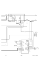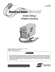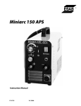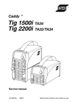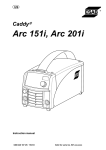
1
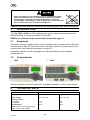
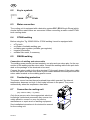
US Caddy™ Tig 1500i Tig 2200i Instruction manual 0460 443 187 US 110405 Valid for serial no. 803-xxx-xxxx to 927-xxx-xxxx 1 2 3 4 1 2 3 USER RESPONSIBILITY . . . . . . . . . . . . . . . . . . . . . . . . . . . . . . . . . . . . . . . . . . . . SAFETY PRECAUTIONS - English . . . . . . . . . . . . . . . . . . . . . . . . . . . . . . . . . . . PRECAUCION DE SEGURIDAD - Spanish . . . . . . . . . . . . . . . . . . . . . . . . . . . . MESURES DE SECURITE - French . . . . . . . . . . . . . . . . . . . . . . . . . . . . . . . . . . DIRECTIVE . . . . . . . . . . . . . . . . . . . . . . . . . . . . . . . . . . . . . . . . . . . . . . . . . . . . . . . . SAFETY . . . . . . . . . . . . . . . . . . . . . . . . . . . . . . . . . . . . . . . . . . . . . . . . . . . . . . . . . . . INTRODUCTION . . . . . . . . . . . . . . . . . . . . . . . . . . . . . . . . . . . . . . . . . . . . . . . . . . . 3.1 3.2 3 3 7 11 15 15 17 Equipment . . . . . . . . . . . . . . . . . . . . . . . . . . . . . . . . . . . . . . . . . . . . . . . . . . . . . . . . . . . . . . . . Control panels . . . . . . . . . . . . . . . . . . . . . . . . . . . . . . . . . . . . . . . . . . . . . . . . . . . . . . . . . . . . 17 17 4 TECHNICAL DATA . . . . . . . . . . . . . . . . . . . . . . . . . . . . . . . . . . . . . . . . . . . . . . . . . 5 INSTALLATION . . . . . . . . . . . . . . . . . . . . . . . . . . . . . . . . . . . . . . . . . . . . . . . . . . . . 17 19 5.1 5.2 Location . . . . . . . . . . . . . . . . . . . . . . . . . . . . . . . . . . . . . . . . . . . . . . . . . . . . . . . . . . . . . . . . . . Primary input . . . . . . . . . . . . . . . . . . . . . . . . . . . . . . . . . . . . . . . . . . . . . . . . . . . . . . . . . . . . . 19 19 6 OPERATION . . . . . . . . . . . . . . . . . . . . . . . . . . . . . . . . . . . . . . . . . . . . . . . . . . . . . . . 20 6.1 6.2 6.3 6.4 6.5 6.6 6.7 Connections and control devices . . . . . . . . . . . . . . . . . . . . . . . . . . . . . . . . . . . . . . . . . . . . Key to symbols . . . . . . . . . . . . . . . . . . . . . . . . . . . . . . . . . . . . . . . . . . . . . . . . . . . . . . . . . . . . Water connection . . . . . . . . . . . . . . . . . . . . . . . . . . . . . . . . . . . . . . . . . . . . . . . . . . . . . . . . . . GTAW-welding . . . . . . . . . . . . . . . . . . . . . . . . . . . . . . . . . . . . . . . . . . . . . . . . . . . . . . . . . . . . SMAW-welding . . . . . . . . . . . . . . . . . . . . . . . . . . . . . . . . . . . . . . . . . . . . . . . . . . . . . . . . . . . . Overheating protection . . . . . . . . . . . . . . . . . . . . . . . . . . . . . . . . . . . . . . . . . . . . . . . . . . . . . Connection to cooling unit (only valid for Caddyt Tig 2200i) . . . . . . . . . . . . . . . . . . . . . . . . . . . . . . . . . . . . . . . . . . . . . Turning on the power source . . . . . . . . . . . . . . . . . . . . . . . . . . . . . . . . . . . . . . . . . . . . . . . . 21 22 22 22 22 22 7 MAINTENANCE . . . . . . . . . . . . . . . . . . . . . . . . . . . . . . . . . . . . . . . . . . . . . . . . . . . . 23 6.8 7.1 22 23 Inspection and cleaning . . . . . . . . . . . . . . . . . . . . . . . . . . . . . . . . . . . . . . . . . . . . . . . . . . . . 24 8 FAULT-TRACING . . . . . . . . . . . . . . . . . . . . . . . . . . . . . . . . . . . . . . . . . . . . . . . . . . 9 ORDERING SPARE PARTS . . . . . . . . . . . . . . . . . . . . . . . . . . . . . . . . . . . . . . . . . 10 DISMANTLING AND SCRAPPING . . . . . . . . . . . . . . . . . . . . . . . . . . . . . . . . . . . SCHEMATIC DIAGRAM . . . . . . . . . . . . . . . . . . . . . . . . . . . . . . . . . . . . . . . . . . . . . . . . SCHEMATIC DIAGRAM . . . . . . . . . . . . . . . . . . . . . . . . . . . . . . . . . . . . . . . . . . . . . . . . ORDERING NUMBER . . . . . . . . . . . . . . . . . . . . . . . . . . . . . . . . . . . . . . . . . . . . . . . . . ACCESSORIES . . . . . . . . . . . . . . . . . . . . . . . . . . . . . . . . . . . . . . . . . . . . . . . . . . . . . . . 24 25 25 26 26 32 33 Rights reserved to alter specifications without notice. TOCa -2- US Be sure this information reaches the operator. You can get extra copies through your supplier. These INSTRUCTIONS are for experienced operators. If you are not fully familiar with the principles of operation and safe practices for arc welding equipment, we urge you to read our booklet, “Precations and Safe Practices for Arc, Cutting and Gouging, “Form 52-529. Do NOT permit untrained persons to install, operate, or maintain this equipment. Do NOT attempt to install or operate this equipment until you have read and fully understand these instructions. If you do not fully understand these instructions, contact your supplier for further information. Be sure to read the Safety Precautions before installing or operating this equipment. 1 USER RESPONSIBILITY This equipment will perform in conformity with the description thereof contained in this manual and accompanying labels and/or insert when installed, operated, maintained and repaired in accordance with the instruction provided. This equipment must be checked periodically. Malfunctioning or poorly maintained equipment should not be used. Parts that are broken, missing, worn, distorted or contaminated should be replaced immediately. Should such repair or replacement become necessary, the manufacturer recommends that a telephone or written request for service advice be made to the Authorized Distributor from whom it was purchased. This equipment or any of its parts should not be altered without the prior written approval of the manufacturer. The user of this equipment shall have the sole responsibility for any malfunction which results from improper use, faulty maintenance, damage improper repair or alteration by anyone other than the manufacturer or a service facility designated by the manufacturer. 2 SAFETY PRECAUTIONS - English WARNING: These Safety Precautions are for your protection. They summarize precautionary information from the references listed in Additional Safety Information section. Before performing any installation or operating procedures, be sure to read and follow the safety precautions listed below as well as all other manuals, material safety data sheets, labels, etc. Failure to observe Safety Precautions can result in injury or death. PROTECT YOURSELF AND OTHERS Some welding, cutting and gouging precesses are noisy and require ear protection. The arc, like the sun, emits ultraviolet (UV) and other radiation and can injure skin and eyes. Hot metal can cause burns. Training in the proper use of the processes and equipment is essential to prevent accidents. Therefore: 1. Always wear safety glasses with side shields in any work area, even if welding helmets face shields and goggles are also required. 2. Use a face shield fitted with the correct filter and cover plates to protect your eyes, face, neck and ears from sparks and rays of the arc when operating or observing operations. Warn bystanders not to watch the arc and not to expose themselves to the rays of the electric-arc or hot metal. 3. Wear flameproof gauntlet type gloves, heavy long-sleeve shirt, cuffless trousers, high-topped shoes and a welding helmet or cap for protection, to protect against arc rays and hot sparks or hot metal. A flameproof apron may also be desirable as protection against radiated heat and sparks. -3US warnings US 4. Hot sparks or metal can lodge in rolled up sleeves, trouser cuffs, or pockets. Sleeves and collars should be kept buttoned and open pockets eliminated from the front of clothing. 5. Protect other personnel from arc rays and hot sparks with a suitable nonflammable partition or curtains. 6. Use goggles over safety glasses when chipping slag or grinding. Chipped slag may be hot and can fly far. Bystanders should also wear goggles over safety glasses. FIRES AND EXPLOSIONS Heat from flames and arcs can start fires. Hot slag or sparks can also cause fires and explosions. Therefore: 1. Remove all combustible materials well away from the work area or cover the materials with a protective nonflammable covering. Combusible materials include wood, clot, sawdust, liquid and gas fuels, solvents, pants and coatings papper, etc. 2. Hot sparks or hot metal can fall through cracks or crevices in floors or wall openings and cause a hidden smoldering fire or fires on the floor below. Make certain that such openings are protected from hot sparks and metal. 3. Do not weld, cut or perform other hot work until the workpiece has been completely cleaned so that there are no substances on the workpiece which might produce flammable or toxic vapors. Do not do hot work on closed containers. They may explode. 4. Have fire extinguishing equipment handy for instant use, such as a garden hose, water pail, sand bucket, or portable fire extinguisher. Be sure you are trained in its use. 5. Do not use equipment beyond its ratings. For example, overloaded welding cable can overheat and create a fire hazard. 6. After completing operations, inspect the work area to make certain there are no hot sparks or hot metal which could cause a later fire. Use fire watchers when necessary. 7. For additional information refer to NFPA Standard 51B, “Fire Prevention in Use of Cutting and Welding Processes”, available from the National Fire Protection Association, Batterymarch Park, Quincy, MA 02269. ELECTRICAL SHOCK Contact with live electrical parts and ground can cause severe injury or death. DO NOT use AC welding current in damp areas, if movement is confined, or if there is danger of falling. Therefore: 1. Be sure the power source frame (chassis) is connected to the ground system of the input power. 2. Connect the workpiece to a good electrical ground. 3. Connect the work cable to the workpiece. A poor or missing connection can expose you or others to a fatal shock. 4. Use well-maintained equipment. Replace worn or damaged cables. 5. Keep everything dry, including clothing, work area, cables, torch/electrode holder and power source. 6. Make sure that all parts of your bady are insulated from work and from ground. 7. Do not stand directly on metal or the earth while working in tight quarters or a damp area; stand on dry boards or an insulating platform and wear rubber-soled shoes. 8. Put on dry, hole-free gloves before turning on the power. 9. Turn off the power before removing your gloves. 10. Refer to ANSI/ASC Standard Z49.1 (listed on next page) for specific grounding recommendations. Do not mistake the work lead for a ground cable. -4US warnings US ELECTRIC AND MAGNETIC FIELDS May be dangerous. Electric current flowing through any conductor causes localized Electric and Magnetic Fields (EMF). Welding and cutting current creates EMF around welding cables and welding machines. Therefore: 1. Welders having pacemakers should consult their physician before welding. EMF may interfere with some pacemakers. 2. Exposure to EMF may have other health effects which are unknown. 3. Welders should use the following procedures to minimize exposure to EMF: a. Route the electrode and work cables together. Secure them with tape when possible. b. Never coil the torch or work cable around your body. c. Do not place your body between the torch and work cables. Route cables on the same side of your body. d. Connect the work cable to the workpiece as close as possible to the area being welded. e. Keep welding power source and cables as far away from your body as possible. FUMES AND GASES Fumes and gases, can cause discomfort or harm, particularly in confined spaces. Do not breathe fumes and gases. Shielding gases can cause asphyxiation. Therfore: 1. Always provide adequate ventilation in the work area by natural or mechanical means. Do not weld, cut or gouge on materials such as galvanized steel, stainless steel, cooper, zinc, lead beryllium or cadmium unless positive mechanical ventilation is provided. Do not breathe fumes from these materials. 2. Do not operate near degreasing and spraying operations. The heat or arc can react with chlorinated hydrocarbon vapors to form phosgene, a highly toxic gas and other irritant gases. 3. If you develop momentary eye, nose or throat irritation while operating, this is an indication that ventilation is not adequate. Stop work and take necessary steps to improve ventilation in the work area. Do not continue to operate if physical discomfort persists. 4. Refer to ANSI/ASC Standard Z49.1 (see listing below) for specific ventilation recommendations. 5. WARNING: This product when used for welding or cutting, produces fumes or gases which contain chemicals known to the State of Californa to cause birth defects and in some cases cancer (California Health & Safety Code §25249.5 et seq.) CYLINDER HANDLING Cylinders, if mishandled, can rupture and violently release gas. Sudden rupture of cylinder valve or relief device can injure or kill. Therefore: 1. Use the proper gas for the process and use the proper pressure reducing regulator designed to operate from the compressed gas cylinder. Do not use adaptors. Maintain hoses and fittings in good condition. Follow manufacturer's operating instructions for mounting regulator to a compressed gas cylinder. 2. Always secure cylinders in an upright position by chain or strap to suitable hand trucks, undercarriages, benches, wall, post or racks. Never secure cylinders to work tables or fixtures where they may become part of an electrical circuit. 3. When not in use, keep cylinder valves closed. Have valve protection cap in place if regulator is not connected. Secure and move cylinders by using suitable hand trucks. 4. Locate cylinders away from heat, sparks and flames. Never strike an arc on a cylinder. 5. For additional information, refer to CGA Standard P-1, “Precations for Safe Handling of Comporessed Gases in Cylinders”, which is available from Compressed Gas Association, 1235 Jefferson Davis Highway, Arlington, VA 22202. -5US warnings US EQUIPMENT MAINTENANCE Faulty or improperly maintained equipment can cause injury or death. Therefore: 1. Always have qualified personnel perform the installaion, troubleshooting and maintenance work. Do not perform any electrical work unless you are qualified to perform such work. 2. Before performing any maintenance work inside a power source, disconnect the power source from the incoming electrical power. 3. Maintain cables, grounding wire, connections, power cord and power supply in safe working order. Do not operate any equipment in faulty condition. 4. Do not abuse any equipment or accessories. Keep equipment away from heat sources such as furnaces, wet conditions such as water puddles, oil or grease, corrosive atmospheres and inclement weather. 5. Keep all safety devices and cabinet covers in position and in good repair. 6. Use equipment only for its intended purpose. Do not modify it in any manner. ADDITIONAL SAFETY INFORMATION For more information on safe practices for electric arc welding and cutting equipment, ask your supplier for a copy of “Precautions and Safe Practices for Arc Welding, Cutting and Gouging”, Form 52-529. The following publications, which are available from the American Welding Society, 550 N.W. LeJuene Road, Miami, FL 33126, are recommended to you: 1. 2. 3. 4. 5. 6. 7. 8. ANSI/ASC Z49.1 - “Safety in Welding and Cutting” AWS C5.1 . “Recommended Practices for Plasma Arc Welding” AWS C5.2 - “Recommended Practices for Plasma Arc Cutting“ AWS C5.3 - “Recommended Practices for Air Carbon, Arc Gouging and Cutting” AWS C5.5 - “Recommended Practices for Gas Tungsten Arc Welding” AWS C5.6 - “Recommended Practices for Gas Metal Arc welding” AWS SP - “Safe practices” - Reprint, Welding Handbook ANSI/AWS F4.1 - “Recommended Safe Practices for Welding and Cutting of Containers That Have Held Hazardous Substances” MEANING OF SYMBOLS As used throughout this manual: Means Attention! Be Alert! Means immediate hazards which, if not avoided, will result in immediate, serious personal injury or loss of life. Means potential hazards which could result in personal injury or loss of life. Means hazards which could result in minor personal injury. -6US warnings US 3 PRECAUCION DE SEGURIDAD - Spanish ADVERTENCIA: Estas Precauciones de Seguridad son para su protección. Ellas hacen resumen de información proveniente de las referencias listadas en la sección ”Información Adicional Sobre La Seguridad”. Antes de hacer cualquier instalación o procedimiento de operación, asegúrese de leer y seguir las precauciones de seguridad listadas a continuación así como también todo manual, hoja de datos de seguridad del material, calcomanias, etc. El no observar las Precauciones de Seguridad puede resultar en daño a la persona o muerte. PROTEJASE USTED Y A LOS DEMAS Algunos procesos de soldadura, corte y ranurado son ruidosos y requiren protección para los oídos. El arco, como el sol , emite rayos ultravioleta (UV) y otras radiaciones que pueden dañar la piel y los ojos. El metal caliente causa quemaduras. EL entrenamiento en el uso propio de los equipos y sus procesos es esencial para prevenir accidentes. Por lo tanto: 1. Utilice gafas de seguridad con protección a los lados siempre que esté en el área de trabajo, aún cuando esté usando careta de soldar, protector para su cara u otro tipo de protección. 2. Use una careta que tenga el filtro correcto y lente para proteger sus ojos, cara, cuello, y oídos de las chispas y rayos del arco cuando se esté operando y observando las operaciones. Alerte a todas las personas cercanas de no mirar el arco y no exponerse a los rayos del arco eléctrico o el metal fundido. 3. Use guantes de cuero a prueba de fuego, camisa pesada de mangas largas, pantalón de ruedo liso, zapato alto al tobillo, y careta de soldar con capucha para el pelo, para proteger el cuerpo de los rayos y chispas calientes provenientes del metal fundido. En ocaciones un delantal a prueba de fuego es necesario para protegerse del calor radiado y las chispas. 4. Chispas y partículas de metal caliente puede alojarse en las mangas enrolladas de la camisa, el ruedo del pantalón o los bolsillos. Mangas y cuellos deberán mantenerse abotonados, bolsillos al frente de la camisa deberán ser cerrados o eliminados. 5. Proteja a otras personas de los rayos del arco y chispas calientes con una cortina adecuada no-flamable como división. 6. Use careta protectora además de sus gafas de seguridad cuando esté removiendo escoria o puliendo. La escoria puede estar caliente y desprenderse con velocidad. Personas cercanas deberán usar gafas de seguridad y careta protectora. FUEGO Y EXPLOSIONES El calor de las flamas y el arco pueden ocacionar fuegos. Escoria caliente y las chispas pueden causar fuegos y explosiones. Por lo tanto: 1. Remueva todo material combustible lejos del área de trabajo o cubra los materiales con una cobija a prueba de fuego. Materiales combustibles incluyen madera, ropa, líquidos y gases flamables, solventes, pinturas, papel, etc. 2. Chispas y partículas de metal pueden introducirse en las grietas y agujeros de pisos y paredes causando fuegos escondidos en otros niveles o espacios. Asegúrese de que toda grieta y agujero esté cubierto para proteger lugares adyacentes contra fuegos. 3. No corte, suelde o haga cualquier otro trabajo relacionado hasta que la pieza de trabajo esté totalmente limpia y libre de substancias que puedan producir gases inflamables o vapores tóxicos. No trabaje dentro o fuera de contenedores o tanques cerrados. Estos pueden explotar si contienen vapores inflamables. 4. Tenga siempre a la mano equipo extintor de fuego para uso instantáneo, como por ejemplo una manguera con agua, cubeta con agua, cubeta con arena, o extintor portátil. Asegúrese que usted esta entrenado para su uso. 5. No use el equipo fuera de su rango de operación. Por ejemplo, el calor causado por cable sobrecarga en los cables de soldar pueden ocasionar un fuego. 6. Después de termirar la operación del equipo, inspeccione el área de trabajo para cerciorarse de que las chispas o metal caliente ocasionen un fuego más tarde. Tenga personal asignado para vigilar si es necesario. -7US warnings US 7. Para información adicional , haga referencia a la publicación NFPA Standard 51B, “Fire Prevention in Use of Cutting and Welding Processes”, available from the National Fire Protection Association, Batterymarch Park, Quincy, MA 02269. CHOQUE ELECTRICO El contacto con las partes eléctricas energizadas y tierra puede causar daño severo o muerte. NO use soldadura de corriente alterna (AC) en áreas húmedas, de movimiento confinado en lugares estrechos o si hay posibilidad de caer al suelo. Por lo tanto: 1. Asegúrese de que el chasis de la fuente de poder esté conectado a tierra através del sistema de electricidad primario. 2. Conecte la pieza de trabajo a un buen sistema de tierra física. 3. Conecte el cable de retorno a la pieza de trabajo. Cables y conductores expuestos o con malas conexiones pueden exponer al operador u otras personas a un choque eléctrico fatal. 4. Use el equipo solamente si está en buenas condiciones. Reemplaze cables rotos, dañados o con conductores expuestos. 5. Mantenga todo seco, incluyendo su ropa, el área de trabajo, los cables, antorchas, pinza del electrodo, y la fuente de poder. 6. Asegúrese que todas las partes de su cuerpo están insuladas de ambos, la pieza de trabajo y tierra. 7. No se pare directamente sobre metal o tierra mientras trabaja en lugares estrechos o áreas húmedas; trabaje sobre un pedazo de madera seco o una plataforma insulada y use zapatos con suela de goma. 8. Use guantes secos y sin agujeros antes de energizar el equipo. 9. Apage el equipo antes de quitarse sus guantes. 10. RUse como referencia la publicación ANSI/ASC Standard Z49.1 (listado en la próxima página) para recomendaciones específicas de como conectar el equipo a tierra. No confunda el cable de soldar a la pieza de trabajo con el cable a tierra. CAMPOS ELECTRICOS Y MAGNETICOS Son peligrosos. La corriente eléctrica fluye através de cualquier conductor causando a nivel local Campos Eléctricos y Magnéticos (EMF). Las corrientes en el área de corte y soldadura, crean EMF alrrededor de los cables de soldar y las maquinas. Por lo tanto: 1. Soldadores u Operadores que use marca-pasos para el corazón deberán consultar a su médico antes de soldar. El Campo Electromagnético (EMF) puede interferir con algunos marcapasos. 2. Exponerse a campos electromagnéticos (EMF) puede causar otros efectos de salud aún desconocidos. 3. Los soldadores deberán usar los siguientes procedimientos para minimizar exponerse al EMF: a. Mantenga el electrodo y el cable a la pieza de trabajo juntos, hasta llegar a la pieza que usted quiere soldar. Asegúrelos uno junto al otro con cinta adhesiva cuando sea posible. b. Nunca envuelva los cables de soldar alrededor de su cuerpo. c. Nunca ubique su cuerpo entre la antorcha y el cable, a la pieza de trabajo. Mantega los cables a un sólo lado de su cuerpo. d. Conecte el cable de trabajo a la pieza de trabajo lo más cercano posible al área de la soldadura. e. Mantenga la fuente de poder y los cables de soldar lo más lejos posible de su cuerpo. -8US warnings US HUMO Y GASES El humo y los gases, pueden causar malestar o daño, particularmente en espacios sin ventilación. No inhale el humo o gases. El gas de protección puede causar falta de oxígeno. Por lo tanto: 1. Siempre provea ventilación adecuada en el área de trabajo por medio natural o mecánico. No solde, corte, o trabajo por medio natural o mecánico. No solde, corte, o ranure materiales con hierro galvanizado, acero inoxidable, cobre, zinc, plomo, berílio, o cadmio a menos que provea ventilación mecánica positiva. No respire los gases producidos por estos materiales. 2. No opere cerca de lugares donde se aplique substancias químicas en aerosol. El calor de los rayos del arco pueden reaccionar con los vapores de hidrocarburo clorinado para formar un fosfógeno, o gas tóxico, y otros irritant es. 3. Si momentáneamente desarrolla inrritación de ojos, nariz o garganta mientras est á operando, es indicación de que la ventilación no es apropiada. Pare de trabajar y tome las medidas necesarias para mejorar la ventilación en el área de trabajo. No continúe operando si el malestar físico persiste. 4. Haga referencia a la publicación ANSI/ASC Standard Z49.1 (Vea la lista a continuación) para recomendaciones específicas en la ventilación. 5. ADVERTENCIA-Este producto cuando se utiliza para soldaduras o cortes, produce humos o gases, los cuales contienen químicos conocidos por el Estado de California de causar defectos en el nacimiento, o en algunos casos, Cancer. (California Health & Safety Code §25249.5 et seq.) MANEJO DE CILINDROS Los cilindros, si no son manejados correctamente, pueden romperse y liberar violentamente gases. Rotura repentina del cilindro, válvula, o válvula de escape puede causar daño o muerte. Por lo tanto: 1. Utilize el gas apropiado para el proceso y utilize un regulador diseñado para operar y reducir la presión del cilindro de gas. No utilice adaptadores. Mantenga las mangueras y las conexiones en buenas condiciones. Observe las instrucciones de operación del manufacturero para montar el regulador en el cilindro de gas comprimido. 2. Asegure siempre los cilindros en posición vertical y amárrelos con una correa o cadena adecuada para asegurar el cilindro al carro, transportes, tablilleros, paredes, postes, o armazón. Nunca asegure los cilindros a la mesa de trabajo o las piezas que son parte del circuito de soldadura. Este puede ser parte del circuito elélectrico. 3. Cuando el cilindro no está en uso, mantenga la válvula del cilindro cerrada. Ponga el capote de protección sobre la válvula si el regulador no está conectado. Asegure y mueva los cilindros utilizando un carro o transporte adecuado. Evite el manejo brusco de los 4. Localize los cilindros lejos del calor, chispas, y flamas. Nunca establezca un arco en el cilindro. 5. Para información adicional, haga referncia a la publicación CGA Standard P-1, “Precations for Safe Handling of Comporessed Gases in Cylinders”, disponible através del Compressed Gas Association, 1235 Jefferson Davis Highway, Arlington, VA 22202. MANTENIMIENTO DEL EQUIPO Equipo defectuoso o mal mantenido puede causar daño o muerte. Por lo tanto: 1. Siempre tenga personal cualificado para efectuar la instalación, diagnóstico, y mantenimiento del equipo. No ejecute ningún trabajo eléctrico a menos que usted esté cualificado para hacer el trabajo. 2. Antes de dar mantenimiento en el interior de la fuente de poder, desconecte la fuente de poder del suministro de electricidad primaria. 3. Mantenga los cables, cable a tierra, conexciones, cable primario, y cualquier otra fuente de poder en buen estado operacional. No opere ningún equipo en malas condiciones. 4. No abuse del equipo y sus accesorios. Mantenga el equipo lejos de cosas que generen calor como hornos, también lugares húmedos como charcos de agua, aceite o grasa, atmósferas corrosivas y las inclemencias del tiempo. 5. Mantenga todos los artículos de seguridad y coverturas del equipo en su posición y en buenas condiciones. -9US warnings US 6. Use el equipo sólo para el propósito que fue diseñado. No modifique el equipo en ninguna manera. INFORMACION ADICIONAL DE SEGURIDAD Para más información sobre las prácticas de seguridad de los equipos de arco eléctrico para soldar y cortar, pregunte a su suplidor por una copia de “Precautions and Safe Practices for Arc Welding, Cutting and Gouging”, Form 52-529. Las siguientes publicaciones, disponibles através de la American Welding Society, 550 N.W. LeJuene Road, Miami, FL 33126, son recomendadas para usted: 1. 2. 3. 4. 5. 6. 7. 8. ANSI/ASC Z49.1 - “Safety in Welding and Cutting” AWS C5.1 . “Recommended Practices for Plasma Arc Welding” AWS C5.2 - “Recommended Practices for Plasma Arc Cutting“ AWS C5.3 - “Recommended Practices for Air Carbon, Arc Gouging and Cutting” AWS C5.5 - “Recommended Practices for Gas Tungsten Arc Welding” AWS C5.6 - “Recommended Practices for Gas Metal Arc welding” AWS SP - “Safe practices” - Reprint, Welding Handbook ANSI/AWS F4.1 - “Recommended Safe Practices for Welding and Cutting of Containers That Have Held Hazardous Substances” SIGNIFICADO DE LOS SIMBOLOS Según usted avanza en la lectura de este folleto: Los Símbolos Significan ¡Atención! ¡Esté Alerta! Se trata de su seguridad. Significa riesgo inmediato que, de no ser evadido, puede resultar inmediatamente en serio daño personal o la muerte. Significa el riesgo de un peligro potencial que puede resultar en serio daño personal o la muerte. Significa el posible riesgo que puede resultar en menores daños a la persona. - 10 US warnings US 4 MESURES DE SECURITE - French ATTENTION : ces règles de sécurité ont pour objet d'assurer votre protection. Elles constituent une synthèse des mesures de sécurité contenues dans les ouvrages de référence repris au chapitre Informations complémentaires relatives à la Sécurité. Avant toute installation ou utilisation du matériel, veillez à lire et à respecter les règles de sécurité énoncées ci-dessous ainsi que dans les divers manuels, fiches de sécurité du matériel, étiquettes, etc. Le non-respect de ces précautions risque d'entraîner des blessures graves ou mortelles. PROTECTION INDIVIDUELLE ET DE L'ENTOURAGE Certains procédés de soudage, découpage et gougeage sont bruyants et requièrent le port de protections auditives. L'arc, tout comme le soleil, émet des ultraviolets (UV) et d'autres rayonnements susceptibles de provoquer des lésions oculaires et dermatologiques. Le métal chaud peut être à l'origine de brûlures. Une formation à l'utilisation correcte des procédés et équipements est essentielle pour prévenir les accidents. En conséquence : 1. Porter impérativement des lunettes avec écrans latéraux dans les zones de travail, même lorsque le port du casque de soudage, de l'écran facial et des lunettes de protection est obligatoire 2. Tant pour exécuter les travaux que pour y assister, porter un écran facial muni de plaques protectrices et de verres filtrants appropriés pour protéger les yeux, le visage, le cou et les oreilles des étincelles et du rayonnement de l'arc. Avertir les personnes se trouvant à proximité qu'elles ne doivent pas regarder l'arc, ni s'exposer à son rayonnement ou à celui du métal incandescent. 3. Porter des gants ignifuges à crispins, une tunique épaisse à longues manches, des pantalons sans rebord, des chaussures à embout d'acier et un casque de soudage ou une casquette pour se protéger du rayonnement de l'arc, des étincelles et du métal incandescent. Le port d'un tablier ininflammable est également recommandé afin de se protéger des étincelles et du rayonnement thermique. 4. Les étincelles ou projections de métal en fusion risquent de se loger dans les manches retroussées, les bords relevés de pantalons ou dans les poches. Il convient donc de boutonner complètement les manches et le col, et de porter des vêtements sans poches à l'avant. 5. Protéger du rayonnement de l'arc et des étincelles les personnes se trouvant à proximité à l'aide d'un écran ou d'un rideau ininflammable approprié. 6. Porter des oculaires et des lunettes de protection pendant le meulage du laitier. Les particules meulées, souvent brûlantes, peuvent être projetées à des distances importantes, de sorte que les personnes se trouvant à proximité doivent également porter des lunettes de protection. INCENDIES ET EXPLOSIONS La chaleur dégagée par les flammes et les arcs peuvent être à l'origine d'incendies. Le laitier incandescent et les étincelles peuvent également provoquer incendies et explosions. En conséquence : 1. Éloigner suffisamment tous les matériaux combustibles de la zone de travail ou les recouvrir complètement d'une bâche ignifuge. Ce type de matériaux comprend le bois, les vêtements, la sciure, les carburants sous forme liquide et gazeuse, les peintures, les enduits, le papier, etc. 2. Les étincelles ou projections de métal en fusion peuvent tomber dans les fissures du sol ou des murs et déclencher une combustion lente dans les planchers ou à l'étage inférieur. Veiller à protéger ces ouvertures pour que les étincelles et projections n'y pénètrent pas. 3. Ne pas procéder à des travaux de soudage, de découpage et autres travaux à chaud tant que la surface n'est pas complètement nettoyée et débarrassée des substances susceptibles de produire des vapeurs inflammables ou toxiques. Ne pas effectuer de travaux à chaud sur des conteneurs fermés pour éviter tout risque d'explosion. 4. Conserver à portée de main un équipement d'extinction – tuyau d'arrosage, seau d'eau ou de sable, extincteur portatif, etc. et s'assurer d'en connaître l'utilisation. 5. Ne pas utiliser l'équipement au-delà de ses spécifications. Par exemple, un câble de soudage surchargé est susceptible de surchauffer et d'être à l'origine d'un incendie. - 11 US warnings US 6. Une fois le travail terminé, inspecter la zone de travail pour s'assurer qu'aucune étincelle ou projection de métal ne risque de déclencher un incendie. Le cas échéant, utiliser des systèmes de détection d'incendie. 7. Pour toute information supplémentaire, voir la norme NFPA 51B relative à la prévention des incendies lors de travaux de découpage et de soudage, disponible auprès de la National Fire Protection Association, Batterymarch Park, Quincy, MA 02269 – USA. CHOC ELECTRIQUE Tout contact avec des éléments sous tension et la masse peut provoquer des blessures graves ou mortelles. NE PAS utiliser de courant de soudage CA dans des zones humides, des lieux exigus ou lorsqu'il existe un risque de chute. En conséquence : 1. Vérifier que le châssis du générateur est bien relié au dispositif de mise à la masse de l'alimentation. 2. Assurer une mise à la masse correcte de la pièce à souder. 3. Connecter le câble de soudage à la pièce à souder. Un raccordement médiocre ou inexistant constitue un risque mortel pour l'utilisateur et son entourage. 4. Utiliser du matériel correctement entretenu. Remplacer les câbles usés ou endommagés. 5. Empêcher l'apparition de toute humidité, notamment sur les vêtements, dans la zone de travail, sur les câbles, la torche de soudage, le porte-électrode et le générateur. 6. S'assurer que le corps est totalement isolé de la pièce à souder et de la masse. 7. Éviter tout contact direct avec du métal ou la masse lors de travaux dans des endroits exigus et en zone humide ; se tenir sur des panneaux ou sur une plate-forme isolante et porter des chaussures à semelles en caoutchouc. 8. Enfiler des gants secs et sans trous avant de mettre l'équipement sous tension. 9. Mettre l'équipement hors tension avant de retirer les gants. 10. Voir la norme ANSI/ASC Z49.1 (voir page suivante) pour les recommandations de mise à la masse. Ne pas confondre le câble de soudage et le câble de masse. CHAMPS ELECTRIQUES ET MAGNETIQUES Danger. Le courant électrique parcourant les conducteurs génère localement des champs électriques et magnétiques (EMF). Le courant de soudage et de découpe crée des EMF autour des câbles de soudage et des postes à souder. En conséquence : 1. Les porteurs de stimulateurs cardiaques consulteront leur médecin avant d'effectuer des travaux de soudage. Les EMF peuvent en effet provoquer des interférences. 2. L'exposition aux EMF peut également avoir des effets méconnus sur la santé. 3. Les soudeurs respecteront les procédures suivantes pour réduire l'exposition aux EMF : a. Rassembler en faisceau les câbles de soudage et d'électrode. Si possible, les attacher avec du ruban adhésif. b. Ne jamais enrouler le câble de la torche ou le câble de soudage autour du corps. c. L'utilisateur ne doit jamais se trouver entre le câble de la torche et le câble de soudage. Faire passer tous les câbles du même côté du corps. d. Connecter le câble de soudage à la pièce à souder, au plus près de l'endroit du soudage. e. S'éloigner au maximum du générateur et des câbles. - 12 US warnings US 1. 2. 3. 4. 5. 1. 2. 3. 4. 5. 1. 2. 3. 4. 5. 6. FUMEES ET GAZ L'inhalation des fumées et gaz peut provoquer des malaises et des dommages corporels, surtout lors de travaux dans les espaces confinés. Ne pas les respirer. Les gaz inertes peuvent causer l'asphyxie. En conséquence : Assurer une aération adéquate de la zone de travail par une ventilation naturelle ou mécanique. Ne pas effectuer de travaux de soudage, découpage ou gougeage sur des matériaux tels que l'acier galvanisé, le cuivre, le zinc, le plomb, le béryllium et le cadmium en l'absence d'une ventilation mécanique adéquate. Ne pas inhaler les fumées dégagées par ces matériaux. Ne pas travailler à proximité d'opérations de dégraissage et de pulvérisation étant donné que la chaleur dégagée et l'arc peut réagir avec les hydrocarbures chlorés pour former du phosgène – un gaz particulièrement toxique – et d'autres gaz irritants. Une irritation momentanée des yeux, du nez ou de la gorge provoquée par les travaux est le signe d'une ventilation inappropriée. Dans ce cas, il convient d'arrêter le travail et de prendre les mesures nécessaires pour améliorer l'aération. Ne pas poursuivre le travail si le malaise persiste. Voir la norme ANSI/ASC Z49.1 (voir ci-dessous) pour les recommandations de ventilation. ATTENTION : utilisé dans des opérations de soudage et de découpage, ce produit dégage des fumées et gaz qui contiennent des substances chimiques reconnues par l'État de Californie comme pouvant être à l'origine de malformations congénitales et de cancers (California Health & Safety Code §25249.5 et seq.). MANIPULATION DES BOUTEILLES DE GAZ Une erreur de manutention des bouteilles de gaz peut les endommager et entraîner une libération violente du gaz. La rupture soudaine de la soupape ou du détendeur peut provoquer des blessures graves ou mortelles. En conséquence : Utiliser le gaz approprié à la pression adéquate, celle-ci étant réglée par un détendeur adapté au type de bouteille utilisée. Ne pas utiliser d'adaptateurs. Garder les tuyaux et accessoires en bon état. Pour le montage du détendeur sur une bouteille de gaz comprimé, suivre les instructions du fabricant. Fixer les bouteilles verticalement – au moyen d'une chaîne ou d'une sangle – à un chariot à bras, un châssis de roulement, un banc, un mur, un piquet ou un rack. Ne jamais attacher les bouteilles aux établis et éléments susceptibles de les intégrer à un circuit électrique. Conserver les bouteilles fermées lorsqu'elles ne sont pas utilisées. Les fermer par un bouchon lorsqu'elles ne sont pas raccordées. Attacher et déplacer les bouteilles à l'aide de chariots adéquats. Éloigner les bouteilles des sources de chaleur, d'étincelles et de flammes nues. Ne jamais déclencher d'arc sur une bouteille de gaz. Pour plus d'informations sur les précautions d'utilisation des bouteilles de gaz comprimé, voir la norme CGA P-1, disponible auprès de la Compressed Gas Association, 1235 Jefferson Davis Highway, Arlington, VA 22202 – USA. ENTRETIEN DE L'EQUIPEMENT Un équipement mal entretenu peut provoquer des blessures graves ou mortelles. En conséquence : Confier l'installation, les dépannages et l'entretien à du personnel qualifié. Ne pas effectuer de travaux électriques si vous ne possédez pas les compétences requises. Mettre l'équipement hors tension avant toute intervention d'entretien sur le générateur. Maintenir en bon état de fonctionnement les câbles, câbles de masse, connexions, cordons d'alimentation et générateurs. Ne jamais utiliser d'équipements défectueux. Ne jamais surcharger les équipements et accessoires. Conserver les équipements à l'écart des sources de chaleur – notamment des fours –, des flaques d'eau, des traces d'huile ou de graisse, des atmosphères corrosives et des intempéries. Laisser en place tous les dispositifs de sécurité et tous les panneaux du tableau de commande en veillant à les garder en bon état. Utiliser l'équipement conformément à l'usage prévu ; n'y apporter aucune modification quelconque. - 13 US warnings US INFORMATIONS COMPLEMENTAIRES RELATIVES A LA SECURITE Pour plus d'informations relatives aux règles de sécurité pour les travaux de gougeage, de découpage et de soudage à l'arc électrique, demander au fournisseur une copie du formulaire 52/529. L'American Welding Society, 550 N.W. LeJuene Road, Miami, FL 33126 – USA, publie les documents suivants dont la lecture est également recommandée : 1. 2. 3. 4. 5. 6. 7. 8. ANSI/ASC Z49.1 - ”Safety in Welding and Cutting” AWS C5.1 . ”Recommended Practices for Plasma Arc Welding” AWS C5.2 - ”Recommended Practices for Plasma Arc Cutting” AWS C5.3 - ”Recommended Practices for Air Carbon, Arc Gouging and Cutting” AWS C5.5 - ”Recommended Practices for Gas Tungsten Arc Welding” AWS C5.6 - ”Recommended Practices for Gas Metal Arc welding” AWS SP - ”Safe practices” - Réédition, Manuel de soudage ANSI/AWS F4.1 - ”Recommended Safe Practices for Welding and Cutting of Containers That Have Held Hazardous Substances” SYMBOLES Signification des symboles utilisés dans ce manuel : = Attention ! Rester prudent ! = danger immédiat ; risque de blessures graves ou mortelles. = danger potentiel ; risque de blessures graves ou mortelles. = danger ; risque de blessures légères. - 14 US warnings US 1 DIRECTIVE DECLARATION OF CONFORMITY ESAB AB, Welding Equipment, SE-695 81 Laxå, Sweden, gives its unreserved guarantee that weld ing power source Tig 1500i, Tig 2200i from serial number 803 are constructed and tested in complian ce with the standard EN 60974-1 /-3 and EN 60974-10 (Class A) in accordance with the requirements of directive (2006/95/EC) and (2004/108/EEC). -------------------------------------------------------------------------------------------------------------Laxå 2008-01-25 Kent Eimbrodt Global Director Equipment and Automation 2 SAFETY Users of ESAB welding equipment have the ultimate responsibility for ensuring that anyone who works on or near the equipment observes all the relevant safety precautions. Safety precautions must meet the requirements that apply to this type of welding equipment. The following recommen dations should be observed in addition to the standard regulations that apply to the workplace. All work must be carried out by trained personnel well-acquainted with the operation of the welding equipment. Incorrect operation of the equipment may lead to hazardous situations which can result in injury to the operator and damage to the equipment. 1. Anyone who uses the welding equipment must be familiar with: S its operation S location of emergency stops S its function S relevant safety precautions S welding 2. The operator must ensure that: S no unauthorized person is stationed within the working area of the equipment when it is started up. S no-one is unprotected when the arc is struck 3. The workplace must: S be suitable for the purpose S be free from drafts 4. Personal safety equipment S Always wear recommended personal safety equipment, such as safety glasses, flame-proof clothing, safety gloves. S Do not wear loose-fitting items, such as scarves, bracelets, rings, etc., which could become trapped or cause burns. 5. General precautions S Make sure the ground cable is connected securely. S Work on high voltage equipment may only be carried out by a qualified electrician. S Appropriate fire extinquishing equipment must be clearly marked and close at hand. S Lubrication and maintenance must not be carried out on the equipment during operation. DO NOT USE THE POWER SOURCE FOR THAWING FROZEN PIPES. - 15 bt34d1aa US ARC WELDING AND CUTTING CAN BE INJURIOUS TO YOURSELF AND OTHERS. TAKE PRECAUSIONS WHEN WELDING. ASK FOR YOUR EMPLOYER'S SAFETY PRACTICES WHICH SHOULD BE BASED ON MANUFACTURERS' HAZARD DATA. ELECTRIC SHOCK - CAN KILL S INSTALL AND EARTH THE WELDING UNIT IN ACCORDANCE WITH APPLICABLE STANDARDS. S DO NOT TOUCH LIVE ELECTRICAL PARTS OR ELECTRODES WITH BARE SKIN, WET GLOVES OR WET CLOTHING. S INSULATE YOURSELF FROM EARTH AND THE WORKPIECE. S ENSURE YOUR WORKING STANCE IS SAFE. FUMES AND GASES - CAN BE DANGEROUS TO HEALTH S KEEP YOUR HEAD OUT OF THE FUMES. S USE VENTILATION, EXTRACTION AT THE ARC, OR BOTH, TO TAKE FUMES AND GASES AWAY FROM YOUR BREATHING ZONE AND THE GENERAL AREA. ARC RAYS - CAN INJURE EYES AND BURN SKIN. S PROTECT YOUR EYES AND BODY. USE THE CORRECT WELDING SCREEN AND FILTER LENS AND WEAR PROTECTIVE CLOTHING. S PROTECT BYSTANDERS WITH SUITABLE SCREENS OR CURTAINS. FIRE HAZARD S SPARKS (SPATTER) CAN CAUSE FIRE. MAKE SURE THEREFORE THAT THERE ARE NO INFLAMMABLE MATERIALS NEARBY. NOISE - EXCESSIVE NOISE CAN DAMAGE HEARING S PROTECT YOUR EARS. USE EARMUFFS OR OTHER HEARING PROTECTION. S WARN BYSTANDERS OF THE RISK. MALFUNCTION - CALL FOR EXPERT ASSISTANCE IN THE EVENT OF MALFUNCTION. READ AND UNDERSTAND THE INSTRUCTION MANUAL BEFORE INSTALLING OR OPERATING. PROTECT YOURSELF AND OTHERS! Read and understand the instruction manual before installing or operating. This product is solely intended for arc welding. Any other use may result in personal injury and / or equipment damage. - 16 bt34d1aa US Class A equipment is not intended for use in residential locations where the electrical power is provided by the public low-voltage supply system. There may be potential difficulties in ensuring electromagnic compatibility of class A equipment in those locations, due to conducted as well as radiated disturbances. ESAB can provide you with all necessary welding protection and accessories. 3 INTRODUCTION The Tig 1500i / 2200i is a TIG welding power source, which can also be used for SMAW welding. It can be used direct current (DC). ESAB's accessories for the product can be found on page 33. 3.1 Equipment The power source is supplied with a 9.8 feet welding cable complete with a Tig-torch, 9.8 feet return cable, 9.8 feet mains cable, instruction manual for power source and control panel, see Ordering information on page 32. Instruction manuals in other languages can be downloaded from the website, www.esab.com. 3.2 S Control panels S TA33 TA34 See the separate instruction manual for a detailed description of the control panels. 4 TECHNICAL DATA Tig 1500i Tig 2200i/2200iw Mains voltage 230V, $10%, 1∼ 50/60 Hz 230V, $10%, 1∼ 50/60 Hz Mains supply Zmax 0.35 ohm Zmax 0.31 ohm Primary current Imax GTAW Imax SMAW 14 A 22 A 24 A 25 A 30 W 30 W No-load power demand when in the energy-saving mode, 6.5 min. after welding - 17 bt34d1aa US Tig 1500i Tig 2200i/2200iw Setting range GTAW SMAW 3 A - 150 A 4 A - 150 A 3 A - 220 A 4 A - 170 A Ignition voltage (Upk) 11.5 kV 11.5 kV Permissible load at GTAW 20% duty cycle 25% duty cycle 60% duty cycle 100% duty cycle 220 A / 18.8 V 150 A / 16.0 V 120 A / 14.8 V 110 A / 14.4 V 150 A / 16.0 V 110 A / 14.4 V Permissible load at SMAW 25% duty cycle 60% duty cycle 100% duty cycle 150 A / 26.0 V 100 A / 24.0 V 90 A / 23.6 V 170 A / 26.8 V 130 A / 25.2 V 110 A / 24.4 V Power factor at maximum current GTAW SMAW 0.98 0.99 0.99 0.99 Efficiency at maximum current GTAW SMAW 77 % 80 % 75 % 81 % Open-circuit voltage GTAW 55-60 V 55-60 V Open-circuit voltage SMAW with VRD from serial number 843 55-60 V < 35 V 55-60 V < 35 V Open-circuit voltage SMAW from serial number 803 72 V 72 V Operating temperature 14 to + 104° F 14 to + 104° F Transportation temperature -4 to + 131° F -4 to + 131° F Constant sound pressure in open-circuit < 70 dB (A) < 70 dB (A) Dimensions, l x b x h 16.5 x 7.4 x 8.2 inch 16.5 x 7.4 x 8.2 inch including the cooling unit - 16.5 x 7.4 x 13.6 inch Weight 20.3 Ibs 20.7 Ibs Shielding gas All types intended for GTAW All types intended for GTAW welding welding 73 PSI 73 PSI Insulation class transformer H H Enclosure class (IEC) Application class IP 23 IP 23 max pressure Duty cycle The duty cycle refers to the time as a percentage of a ten-minute period that you can weld at a cer tain load without overloading. The duty cycle is valid for 104° F. Enclosure class The IP code indicates the enclosure class, i. e. the degree of protection against penetration by solid objects or water. Equipment marked IP 23 is designed for indoor and outdoor use. Application class The symbol indicates that the power source is designed for use in areas with increased electrical hazard. - 18 bt34d1aa US Mains supply, Zmax Maximum permissible line on the network impedance in accordance with IEC 61000-3-11. 5 INSTALLATION The installation must be done by a professional. THE CHASSIS MUST BE CONNECTED TO AN APPROVED ELECTRICAL GROUND. FAILURE TO DO SO MAY RESULT IN ELECTRICAL SHOCK, SEVERE BURNS OR DEATH. Mains supply requirements High power equipment may, due to the primary current drawn from the mains supply, influence the power quality of the grid. Therefore connection restrictions or requirements regarding the maximum permissible mains impedance or the required minimum supply capacity at the interface point to the public grid may apply for some types of equipment (see technical data). In this case it is the responsibility of the installer or user of the equipment to ensure, by consultation with the distrubution network operator if necessary, that the equipment may be connected. 5.1 Location Position the welding power source such that its cooling air inlets and outlets are not obstructed. 5.2 Primary input ELECTRIC SHOCK CAN KILL! PRECAUTIONARY MEASURES SHOULD BE TAKEN TO PROVIDE MAXIMUM PROTECTION AGAINST ELECTRICAL SHOCK. BE SURE THAT ALL POWER IS OFF BY OPENING THE LINE (WALL) DISCONNECT SWITCH WHEN PRIMARY ELECTRICAL CONNECTIONS ARE MADE TO THE POWER SOURCE. BE SURE TO CHECK YOUR INPUT LEADS WITH A VOLTMETER TO MAKE SURE ALL POWER IS OFF. Check that the welding power source is connected to the correct mains power supply voltage, and that it is protected by the correct fuse size. A protective earth connection must be made in accordance with regulations. Rating plate with supply connection data - 19 bt34d1aa US Recommended fuse sizes and minimum cable area Tig 1500i Mains voltage Mains frequency Mains cable area mm2 Phase current I1eff Fuse anti-surge type C MCB Tig 2200i/2200iw GTAW SMAW GTAW SMAW 230 V 10 %, 1 50/60 Hz 3G2.5 9A 230 V 10 %, 1 50/60 Hz 3G2.5 11 A 230 V 10 %, 1 50/60 Hz 3G2.5 11 A 230 V 10 %, 1 50/60 Hz 3G2.5 14 A 16 A 16 A 16 A 16 A 13 A 13 A 16 A 16 A NOTE! The mains cable areas and fuse sizes as shown above are in accordance with Swedish regulations. Use the welding power source in accordance with the relevant national regulations. 6 OPERATION General safety regulations for the handling of the equipment can be found on page 3. Read through before you start using the equipment! BEFORE MAKING ANY CONNECTIONS TO THE POWER SOURCE OUTPUT TERMINALS, MAKE SURE THAT ALL PRIMARY INPUT POWER TO THE MACHINE IS OFF. ELECTRIC SHOCK CAN KILL! “MACHINERY LOCKOUT PROCEDURES” SHOULD BE EMPLOYED. IF IT IS NOT POSSIBLE TO USED PADLOCKS, ATTACH A RED TAG TO THE LINE DISCONNECT SWITCH (OR FUSE BOX) WARNING OTHERS THAT THE CIRCUIT IS BEING WORKED ON. ELECTRIC SHOCK CAN KILL! WHEN THE CONTACTOR SWITCH IS IN THE “ON” POSITION, OUTPUT POWER WILL BE PRESENT THROUGHOUT THE WELDING CIRCUIT; IE. CABLES, WIRE FEEDER, WIRE SPOOL, DRIVE STAND, GUN AND ELECTRODE. BE SURE ALL ARE CLEAR OF THE WORKPIECE OR ARCING WILL RESULT. Never operate the power source with the cover removed. In addition to the safety hazards, improper cooling may cause damage to the components. Keep side panels closed when unit is energized. Welding helmet, gloves and other personal protection should always be worn when welding. - 20 bt34d1aa US 6.1 1 Connections and control devices 7 Mains switch 8 Mains cable 9 Connection for shiedling gas 4 Connection (+) for the return cable for GTAW. SMAW: for the return cable or the welding cable. Connection for the remote control unit, only valid for TA34 Control panel (see separate instruction manual) Connection for the Tig-torch 10 5 Connection for gas to the Tig-torch 11 6 Connection (-) for the Tig-torch SMAW: return cable or welding cable 12 Connection BLUE, with ELP* for cooling water from the cooling unit Connection RED for cooling water to the cooling unit. Refilling of cooling water 2 3 * ESAB Logic Pump, see under 6.3 - 21 bt34d1aa US 6.2 Key to symbols SMAW 6.3 GTAW Water connection The cooling unit is equipped with a detection system ELP (ESAB Logic Pump) which checks that the water hoses are connected. When connecting a water-cooled GTAW torch cooling starts. 6.4 GTAW-welding Before using the Tig 1500i/2200i for GTAW welding it must be equipped with: S S S S S a Tig torch a cylinder of suitable welding gas a welding gas regulator (suitable gas regulator) tungsten electrodes suitable filler metal, if necessary 6.5 SMAW-welding Connection of welding and return cable The welding power source has two terminals, one plus and one minus pole, for the con nection of the welding and the return cable. Connect the welding cable to the pole indic ated on the package of the electrode to be used. Connect the return cable to the other terminal. Fit the earth clamp of the return cable to the work-piece and make sure there is good contact between the work-piece and the return cable terminal on the welding power source. 6.6 Overheating protection The power source has two thermal overload trips which operate if the internal temperature becomes too high. A fault code is shown in the panel. They reset automatically when the temperature has fallen. 6.7 Connection to cooling unit (only valid for Caddyt Tig 2200i) Only those persons who have appropriate electrical knowledge (authorized personnel) may remove the safety plates to connect or carry out service, maintenance or repair work on welding equipment. See installation instructions in the instruction manual for the cooling unit. - 22 bt34d1aa US 6.8 Turning on the power source Turn on the mains power by turning the mains switch to the ”1” position. Turn the unit off by turning the switch to the ”0” position. Whether the mains power supply is interrupted or the power unit is switched off in the normal manner, welding data will be stored and is available next time the unit is started. 7 MAINTENANCE Regular maintenance is important for safe, reliable operation. Only those persons who have appropriate electrical knowledge (authorized personnel) may remove the safety plates to connect or carry out service, maintenance or repair work on welding equipment. INSPECTION, TROUBLESHOOTING, AND REPAIR OF THIS EQUIPMENT SHOULD BE UNDERTAKEN BY A COMPETENT INDIVIDUAL HAVING AT LEAST GENERAL EXPERIENCE IN THE MAINTENANCE AND REPAIR OF SEMI-CONDUCTOR ELECTRONIC EQUIPMENT. MAINTENANCE OR REPAIR SHOULD NOT BE UNDERTAKEN BY ANYONE NOT HAVING SUCH QUALIFICATIONS. FAILURE TO REPLACE WORN OR DAMAGED CABLES MAY RESULT IN A BARE CABLE TOUCHING A GROUNDED OBJECT. THE RESULTING ELECTRICAL ARC MAY INJURE UNPROTECTED EYES AND WILL PRESENT A SERIOUS FIRE HAZARD. BODY CONTACT WITH A BARE CABLE, CONNECTOR, OR CONDUCTOR MAY RESULT IN SEVERE ELECTRICAL SHOCK, CAUSING SERIOUS BURNS OR DEATH. Supplier warranty is void if customer attempts any work on product during the warranty period. Do not use filters on this unit as they would restrict the volume of intake air required for proper cooling. Output ratings on this unit are based on an unobstructed supply of cooling air drawn over its internal components. Warranty is void if any type of filtering device is used. - 23 bt34d1aa US If this power source does not operate properly, stop work immediately and investigate the cause of the malfunction. Maintenance work must be perfomed by an experienced person, and electrical work by a trained electrician. Do not permit untrained persons to inspect, clean, or repair this power source. Use only recommended replacement parts. 7.1 Inspection and cleaning Power source Check regularly that the welding power source is not clogged with dirt. How often and which cleaning methods apply depend on: the welding process, arc times, placement, and the surrounding environment. It is normally sufficient to blow down the power source with dry compressed air (reduced pressure) once a year. Clogged or blocked air inlets and outlets otherwise result in overheating. Welding torch The welding torch's wear parts should be cleaned and replaced at regular intervals in order to achieve trouble-free welding. 8 FAULT-TRACING ELECTRICAL SERVICE AND REPAIR SHOULD BE ATTEMPTED ONLY BY A TRAINED ELECTRICIAN. Try these recommended checks and inspections before sending for an authorised service technician. Type of fault No arc. Corrective action S S S S Check that the mains power supply switch is turned on. Check that the welding current supply and return cables are correctly connected. Check that the correct current value is set. Check the mains power supply. The welding current is interrupted during welding. S S Check to see whether the thermal cut-outs have tripped. Check the mains power supply fuses. The thermal cut-out trips frequently. S Make sure that you are not exceeding the rated data for the welding power source (i.e. that the unit is not being overloaded). Make sure that the power source is clean. S Poor welding performance. S S S S Check that the welding current supply and return cables are correctly connected. Check that the correct current value is set. Check that the correct electrodes are being used. Check the gas flow. - 24 bt34d1aa US 9 ORDERING SPARE PARTS Do not make any repairs to equipment unless you are fully qualified, as described in the maintenance section. Repair and electrical work should be performed by an authorized ESAB service personnel. Use only ESAB original replacement and wear parts. Tig 1500i, Tig 2200i is designed and tested in accordance with the international and European standards IEC/EN 60974-1, IEC/EN 60974-3 and IEC/EN 60974-10. It is the obligation of the service unit which has carried out the service or repair work to make sure that the product still conforms to the said standard. When ordering replacement parts, order by part number and part name, as illustrated on the figure. Always provide the series or serial number on the unit on which the parts will be used. The serial number is stamped on the rating plate. 10 DISMANTLING AND SCRAPPING Welding equipment primarily consists of steel, plastic and non-ferrous metals, and must be handled according to local environmental regulations. Coolant must also be handled according to local environmental regulations. Dispose of electronic equipment at the recycling facility! In observance of European Directive 2002/96/EC on Waste Electrical and Electronic Equipment and its implementation in accordance with national law, electrical and/or electronic equipment that has reached the end of its life must be disposed of at a recycling facility. As the person responsible for the equipment, it is your responsibility to obtain information on approved collection stations. For further information contact the nearest ESAB dealer. - 25 bt34d1aa Schematic diagram Schematic diagram Tig 1500i TA34 - 26 bt34e Edition 110405 - 27 bt34e Edition 110405 Tig 1500i TA33 - 28 bt34e Edition 110405 - 29 bt34e Edition 110405 Tig 2200i TA33/TA34 - 30 bt34e Edition 110405 - 31 bt34e Edition 110405 Tig 1500i, Tig 2200i Ordering number Ordering no. Product 0460 450 480 Caddyt Tig 1500i, TA33 incl. 9.8 ft SMAW cable kit complete and Tig torch TXH 150, 13.1 ft 0460 450 481 Caddyt Tig 2200i, TA33 incl. 9.8 ft SMAW cable kit complete and Tig torch TXH 200, 13.1 ft 0460 450 482 Caddyt Tig 1500i, TA34 incl. 9.8 ft m SMAW cable kit complete and Tig torch TXH 150, 13.1 ft 0460 450 483 Caddyt Tig 2200i, TA34 incl. 9.8 ft m SMAW cable kit complete and Tig torch TXH 200, 13.1 ft 0460 450 484 Caddyt Tig 2200iw, TA33 incl. water cooler CoolMini, 9.8 ft m SMAW cable kit complete and Tig torch TXH 250w, 13.1 ft 0460 450 485 Caddyt Tig 2200iw, TA34 incl. water cooler CoolMini, 9.8 ft m SMAW cable kit complete and Tig torch TXH 250w, 13.1 ft Filename Type Product 0460 447 087 Instruction manual Control panel, Caddyt TA33, TA34 0459 839 025 Spare parts list Welding power source, Tig 1500i, Tig 2200i, Tig 2200iw 0459 839 028 Spare parts list Control panel, Caddyt TA33 0459 839 028 Spare parts list Control panel, Caddyt TA34 Instruction manuals and the spare parts list are available on the Internet at www.esab.com - 32 bt34oa Edition 110405 Tig 1500i, Tig 2200i Accessories Strap . . . . . . . . . . . . . . . . . . . . . . . . . . . . . . . . . . . 0460 265 001 Cable holder . . . . . . . . . . . . . . . . . . . . . . . . . . . . 0460 265 002 Shoulder strap . . . . . . . . . . . . . . . . . . . . . . . . . . 0460 265 003 Trolley . . . . . . for 1.32-2.64 Gallons gasbottle . . . . . . . . . . . . . 0459 366 885 Trolley for 5.28-13.20 Gallons gasbottle . . . . . . . . . . . . 0459 366 886 Trolley for 5.28-13.20 Gallons gasbottle . . . . . . . . . . . - 33 bt34a11aa 0460 330 880 Edition 110405 Tig 1500i, Tig 2200i Tig torch TXH 150 13.1 ft . . . . . . . . . . . . . . . . . . . . . . . . . TXH 150 26.2 ft . . . . . . . . . . . . . . . . . . . . . . . . . TXH 200 13.1 ft . . . . . . . . . . . . . . . . . . . . . . . . . TXH 200 26.2 ft . . . . . . . . . . . . . . . . . . . . . . . . . TXH 250w 13.1 ft . . . . . . . . . . . . . . . . . . . . . . . . . TXH 250w 26.2 ft . . . . . . . . . . . . . . . . . . . . . . . . . 0460 011 842 0460 011 882 0460 012 840 0460 012 880 0460 013 840 0460 013 880 Tig torch TXH 150r 13.1 ft . . . . . . . . . . . . . . . . . . . . . . . . . TXH 150r 26.2 ft . . . . . . . . . . . . . . . . . . . . . . . . . TXH 200r 13.1 ft . . . . . . . . . . . . . . . . . . . . . . . . . TXH 200r 26.2 ft . . . . . . . . . . . . . . . . . . . . . . . . . TXH 250wr 13.1 ft . . . . . . . . . . . . . . . . . . . . . . . . TXH 250wr 26.2 ft . . . . . . . . . . . . . . . . . . . . . . . . 0462 011 842 0462 011 882 0462 012 840 0462 012 880 0462 013 840 0462 013 880 Remote control adapter RA12 12 pole . . . . 0459 491 910 For analogue remote controls to CAN based equipment. Only with panel TA34 Remote control unit MTA1 CAN . . . . . . . . . . 0459 491 880 MIG/MAG: wire feed speed and voltage MMA: current and arc force TIG: current, pulse and background current Only with panel TA34 Remote control unit M1 10Prog CAN . . . . . . 0459 491 882 Choice of on of 10 programs MIG/MAG: voltage deviation TIG and MMA: current deviation Only with panel TA34 Remote control unit AT1 CAN . . . . . . . . . . . . 0459 491 883 MMA and TIG: current Only with panel TA34 Remote control unit AT1 CF CAN . . . . . . . . . 0459 491 884 MMA and TIG: rough and fine setting of current. Only with panel TA34 - 34 bt34a11aa Edition 110405 Tig 1500i, Tig 2200i Welding cable kit . . . . . . . . . . . . . . . . . . . . . . . . 0700 006 884 Return cable kit . . . . . . . . . . . . . . . . . . . . . . . . . 0700 006 885 Remote cable CAN 4 pole - 12 pole 16.4 ft . . . . . . . . . . . . . . . . . . . . . . . . . . . . . . . . . . 32.8 ft . . . . . . . . . . . . . . . . . . . . . . . . . . . . . . . . . . 49.2 ft . . . . . . . . . . . . . . . . . . . . . . . . . . . . . . . . . . 82.0 ft . . . . . . . . . . . . . . . . . . . . . . . . . . . . . . . . . . 0.8 ft . . . . . . . . . . . . . . . . Only with panel TA34 0459 544 880 0459 554 881 0459 554 882 0459 554 883 0459 554 884 Foot pedal TI Foot CAN . . . . . . . . . . . . . . . . . . 0460 315 880 Cooling unit CoolMini Assembly kit . . . . . . . . . . . . . . . . . . . . . . . . . . . 0460 144 880 0460 509 880 AH 0836 Only for Tig 2200i - 35 bt34a11aa Edition 110405 ESAB Welding & Cutting Products, Florence, SC Welding Equipment COMMUNICATION GUIDE - CUSTOMER SERVICES A B C CUSTOMER SERVICE QUESTIONS: Telephone: (800) 362-7080 / Fax: (800) 634-7548 Order Entry Product Availability Pricing Order Information ENGINEERING SERVICE: Telephone: (834) 664-4416 / Fax: (800) 446-5693 Warranty Returns Authorized Repair Stations Hours: 7.30 AM to 5:00 PM EST Welding Equipment Troubleshooting TECHNICAL SERVICE: Telephone: (800) ESAB-123 / Fax: (843) 664-4452 Part Numbers Technical Applications Specifications Hours: 8.00 AM to 7:00 PM EST Returns Hours: 8.00 AM to 5:00 PM EST Equipment Recommendations D LITERATURE REQUESTS: Telephone: (843) 664-5562 / Fax: (843) 664-5548 E WELDING EQUIPMENT REPAIRS: Telephone: (843) 664-4487 / Fax: (843) 664-5557 Repair Estimates Repair Status Hours: 7.30 AM to 3:30 PM EST WELDING EQUIPMENT TRAINING: Telephone: (843) 664-4428 / Fax: (843) 679-5864 Training School Information and Registrations Hours: 7.30 AM to 4:00 PM EST F Hours: 7.30 AM to 4:00 PM EST G WELDING PROCESS ASSISTANCE: Telephone: (800) ESAB-123 Hours: 7.30 AM to 4:00 PM EST H TECHNICAL ASST. CONSUMABLES: Telephone: (800) 933-7070 Hours: 7.30 AM to 5:00 PM EST IF YOU DO NOT KNOW WHOM TO CALL Telephone: (800) ESAB-123 Fax: (843) 664-4452 Hours: 7:30 AM to 5:00 PM EST or visit us on the web at http://www.esabna.com The ESAB web site offers: Comprehensive Product Information Material Safety Data Sheets Warranty Registration Instruction Literature Download Library Distributor Locator Global Company Information Press Releases Customer Feedback & Support ESAB Welding & Cutting Products 110405 PO BOX 100545, Florence SC 29501-0545 - 36 backp3us