1
LOGIC CONNECTION SPECIFICATIONS
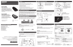
The logic capability of the SLX4L receiver provides two functions: Transmitter Mute Status indication (which can be
used to signal and control other events) and Transmitter Battery status indication. The various logic functions and
their applications are presented in the following pin diagram and descriptions:
Pin 1: Transmitter Mute Status. In Logic mode, Pin 1 can be connected to a remote device and when transmitter
status is Active, logic level is Low (0V). When status is Muted, logic level is High (+5V). Typical applications include providing remote indication of transmitter status and activating external equipment (equalizer,
signal processor, loudspeakers, etc.) when used with a Room Control System (Crestron or AMX for example).
Transmitter Mute control mutes/unmutes an input channel on an automatic mixer. For connections, connect
the transmitter status pin to the podium mic mute input terminal on an automatic mixer. Connect the receiver
logic ground to the mixer logic ground.
NOTE: Whenever the receiver is in Normal mode, Pin 1 indicates transmitter on/off status. When the transmitter is powered ON, logic output level is Low (0V.) When the transmitter is powered OFF, the logic
level is High (+5V)
Pin 2: Logic Ground. For connections, make all logic ground connections to this pin, including the power supply
ground of external logic circuitry. To avoid switching noise, do not connect logic ground to audio, chassis, or
rack grounds.
Pin 3: Transmitter Battery Status. Good Battery status sends a logic level of Low (0V). Low Battery status (1 hour
or less of battery life remaining) sends a logic level of High (+5V). Pin 3 can be used to control a remote
LED when battery is low. It can also be used to indicate low transmitter battery status on a remote control
panel when used with a Room Control System (Crestron or AMX for example).
4