1
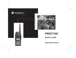
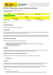
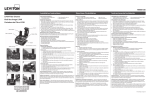
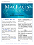
VentSure™ Solar Attic Exhaust Fan
Remote Attic Monitoring Device (Optional)
User Guide
The Remote Attic Monitoring device
allows the user to see the temperature
and humidity conditions in their attic
from nearly anywhere in the home. It
also identifies whether the fan is on or
off and whether it is running on solar or
electric power.
Kit Includes:
• Remote Attic Monitor Holster
• Remote Attic Monitoring Device
• Two (2) AAA Batteries
• Two (2) Mounting Screws
Important Notes
The Remote Attic Monitoring device
is designed to work with VentSure™
Solar Attic Exhaust fans (gable and roof
mount units) installed with the Controller
Module. Do not attempt to use the
Controller Module or Remote Attic
Monitoring device with any other solar
attic fans.
Please ensure your VentSure Solar Attic
Exhaust Fan and Controller Module have
been installed and are working properly
prior to setting up the Remote Attic
Monitoring device.
D
A
E
B
C
F
G
A
B
C
D
Attic Temperature E Fan Mode
F Status Button
House Power
G Channel Switch
Solar Power
Battery Compartment
Attic Humidity
and Thermo Switch
not pictured
Setting the Remote Attic
Monitor After the Controller
Module
Step 1
The Attic-mounted Controller Module
has 2 slide switches: the one on the left
is for selecting the Radio Frequency (RF)
channel and the one on the right is for
selecting the temperature readout in
Celsius (°C) or Fahrenheit (°F). Select
the same RF channel (choice of 1, 2, or
3) on the Remote Attic Monitor and on
the Controller Module. Both must be on
the same channel in order to send and
receive signals. Also, ensure the desired
temperature readout is selected on the
Controller Module.
Step 2
Remove the back panel of the Remote
Attic Monitor. Insert 2 AAA batteries
(included) in the battery compartment.
Replace the back panel of the battery
compartment.
Status Button
When the Status button is pressed, a
beep will sound from the Controller
Module to signify a proper connection
between the Controller Module and
Remote Attic Monitor. The Remote Attic
Monitor’s LCD display will show the
following information:
• Attic Temperature
• Attic Relative Humidity
• Fan Mode—ON, OFF, Intermittent,
or Failure
• House Power—ON
• Solar Power—ON
The status will be displayed for
approximately 20 seconds. Press the
Status button again to refresh the
information after 20 seconds. If the beep
doesn’t sound after pressing the Status
button, no connection has been made
with the Controller Module and the LCD
display will go blank.
Step 3
Test the Remote Attic Monitor by
pressing the Status button once. This will
establish the connection between the
Controller Module and Remote Attic
Monitor. You will hear a “beep” every
time the Status button is pressed. This
verifies the Remote Attic Monitor and
Controller Module RF signals are aligned.
If there is not a beep, check that the
RF channel selector is set to the same
channel. If there still isn’t a beep, move
both devices to an alternative channel
and retry.
Check the following if there is no
display on the Remote Attic Monitor
after pressing the Status button:
Using the Remote Attic
Monitoring Device
• If the problem persists, contact us at
1-800-GET-PINK®.
The Remote Attic Monitor has one status
button on the front below the LCD
display, and a Thermo Switch selector on
the back.
Back of the Remote Attic Monitor
Thermo Switch selector—ON or OFF
The Thermo Switch allows the user to
engage or disengage the temperature
control.
Front of the Remote Attic Monitor
Channel Setting
There are 3 available RF channels. Ensure
the same RF channel is selected on the
Controller Module and Remote Attic
Monitor. The RF channel ID must match
in order to transmit information.
• Batteries have been installed; Replace if
necessary
• RF channel is properly aligned between
the Controller Module and Remote
Attic Monitor
• Controller Module wire connections
are correct
• AC Power adapter is connected to
the Controller Module for after dark
operation
When the Thermo Switch is set to:
• ON mode—Fan will only operate
when the attic temperature reaches
80°F and power is available. Once
running, the fan will shut off when the
temperature drops below 77°F.
• OFF mode—Fan will operate whenever
a source of power is available, regardless
of attic temperature
Note: The only exception is if solar power
has not been generated for 8 hours AND
the Controller Module is installed with the
AC Power Adapter connected to house
electricity. In this instance, the fan will
operate for 10 hours, then shut off for 8
hours or until solar power is generated.
During each of the 10 hours the fan is
operating via electric backup, the fan will
operate for 15 minutes and then shut off
for 15 minutes.
After making a change to the Thermo
Switch on the Remote Attic Monitor:
• Click the Status button and send the
command to the Controller Module.
Source of Power
1. Whenever available, solar power is the default power source. On a typical day with
proper sunlight, the fan will operate until sunset.
2. If solar power is not available, the fan will not operate unless the Controller Module
is installed with the AC power adapter connected to house electricity. The fan will
then continue to operate in the following pre-set mode for 10 hours:
I. ON for 15 minutes and OFF for 15 minutes in a 30-minute period. This is an
efficient cycle for trying to keep the attic temperature close to the outside
temperature.
ii. The cycle will run for a maximum of 10 hours on intermittent house electricity.
iii. The fan will run on solar power whenever solar power becomes available again.
iv. After 10 hours of running on intermittent house electricity, the fan will be turned
off for up to 8 hours, then turned back on, assuming solar power is not available
during this period of time.
• Wait 5 seconds for the Controller
Module to change the fan operation.
Power Source Summary
• Click the Status button again to read
the current fan operation status.
Primary
Power Source
Humidity Control—Always Enabled
The relative humidity sensor is always
enabled (the user cannot disable the
sensor). The fan will be turned on when
attic relative humidity reaches 75%,
regardless of attic temperature. The fan
will turn off when relative attic humidity
drops to 65%.
Daytime—with
sufficient solar power
Evening after sunset
Solar Fan with Controller Module Solar Fan with Controller Module
WITHOUT AC Adapter connected
WITH AC Adapter connected
Solar power
Solar power
No power available
Intermittent house
electricity for 10 hours
Note: The primary power source is always SOLAR. If solar power is not available during the
daytime, the primary power source will switch to house electricity (if the Controller Module is
connected to house electricity) for up to 10 hours or until solar power becomes available.
Refer to the LCD Display Summary to interpret the LCD display and the fan’s
operating status.
Multiple Fan Setup—3 or Less Fans
Assign 1 of the 3 available channels to each of the Controller Modules. A beep will come
from the Controller Module that is communicating with the Remote Attic Monitor. The
user can use the same Remote Attic Monitor to control all 3 fans by selecting the correct
RF channel. Do not assign the same RF channel to 2 or more Controller Modules.
4 or more fans—Consult 1-800-GET-PINK®
Additional Information
Please visit our website www.roofing.owenscorning.com for additional product
information and FAQs. You can also call 1-800-GET-PINK® and one of our Customer
Service Representatives will be able to help you.
LCD Display Summary
LCD Display
House Power
Solar Power
Fan
Operation Summary
(blank)
ON
ON
• Solar power is available
• Fan is running
(blank)
ON
ON
ON
(blank)
ON
•
•
•
•
•
Solar power is availabe
Fan is not running
Attic temperature is < 80°F
Thermo Switch could be ON
To run fan, switch Thermo Switch to OFF, then
press the Status button twice
ON
OFF
(blank)
ONIntermittent
• Solar power is not available
• Fan is powered by house electricity
• Fan is running intermittently, currently in the
15-minute ON mode of the 10-hour cycle
Intermittent
• Solar power is not available
• Fan is powered by house electricity
• Fan is running intermittently, currently in the
15-minute OFF mode of the 10-hour cycle
(blank)
(blank)
ON
(blank)
OFF
•
•
•
•
Solar power is not available
Fan is powered by house electricity
Fan is in the 8-hour OFF mode
Fan will restart when solar power becomes
available, or at the end of the 8-hour OFF mode
Failure
• House electricity is available
• Fan is not running
• Possible problems:
• Loose wiring
• Motor failure
• Controller Module failure
Failure
• Solar power is available
• Fan is not running
• Possible problems:
• Loose wiring
• Motor failure
• Controller Module failure
OWENS CORNING ROOFING AND ASPHALT, LLC
ONE OWENS CORNING PARKWAY
TOLEDO, OHIO, USA 43659
1-800-GET-PINK®
www.roofing.owenscorning.com
Pub. No. 10017988-A. Printed in U.S.A. April 2013. THE PINK PANTHER™ &
©1964–2013 Metro-Goldwyn-Mayer Studios Inc. All Rights Reserved. The
color PINK is a registered trademark of Owens Corning. © 2013 Owens Corning.
All Rights Reserved.
Ventilador extractor solar para ático VentSure™
Dispositivo de monitoreo remoto de ático (Opcional)
Guía del usuario
El dispositivo de monitoreo remoto de
ático permite al usuario ver las condiciones
de temperatura y humedad en el ático
prácticamente desde cualquier lugar del
hogar. Además, identifica si el ventilador
está encendido o apagado y si está
funcionando con energía solar o eléctrica.
El paquete incluye:
• Cartuchera para monitor de ático remoto
• Dispositivo de monitoreo remoto de ático
• Dos (2) baterías AAA
• Dos (2) tornillos de montaje
Notas importantes
El dispositivo de monitoreo remoto de
ático está diseñado para funcionar con los
ventiladores extractores solares para ático
VentSure™ (unidades de montaje en hastial
y en techo) instalados con el módulo del
controlador. No intente utilizar el módulo
del controlador o el dispositivo de monitor
remoto de ático con otros ventiladores
solares para ático.
Asegúrese de que su ventilador extractor
solar para ático VentSure y el módulo del
controlador hayan sido instalados y estén
funcionando correctamente antes de
configurar el dispositivo de monitoreo
remoto de ático.
D
A
E
B
C
G
B
C
D
E
Paso 1
El módulo del controlador de montaje en
ático tiene dos interruptores deslizantes:
el de la izquierda es para seleccionar el
canal de frecuencia de radio (RF) y el de la
derecha es para seleccionar la lectura de
temperatura en Celsius (°C) o Fahrenheit
(°F). Seleccione el mismo canal RF (selección
de 1, 2 ó 3) en el monitor de ático remoto y
en el módulo del controlador. Ambos deben
estar en el mismo canal para enviar y recibir
señales. Además, asegúrese de que se haya
seleccionado la lectura de temperatura
deseada en el módulo del controlador.
Paso 2
Quite el panel trasero del módulo del
controlador. Inserte 2 baterías AAA
(incluidas) en el compartimiento para
baterías. Vuelva a colocar el panel trasero
del compartimiento para baterías.
Paso 3
Pruebe el monitor remoto de ático
presionando una vez el botón "Status"
(estado). Esto establecerá la conexión
entre el módulo del controlador y el
monitor de ático remoto. Escuchará un
pitido cada vez que se presione el botón
"Status". Esto comprueba que las señales
RF del monitor de ático remoto y el
módulo del controlador están alineadas. Si
no escucha un pitido, compruebe que el
selector del canal RF esté configurado en
el mismo canal. Si sigue sin escuchar ningún
pitido, mueva ambos dispositivos hasta un
canal alternativo y vuelva a intentarlo.
Uso del dispositivo de
monitoreo remoto de ático
F
A
Configuración del monitor
remoto de ático después del
módulo del controlador
F Botón "Status"
Temperatura
del ático
(estado)
G Interruptor de canal
Energía del hogar
Energía solar
Compartimiento e
Humedad del ático interruptor térmico no
Modo del ventilador figura en la fotografía
El monitor remoto de ático tiene un
botón de estado en el frente, debajo de
la pantalla LCD y un interruptor selector
térmico en la parte trasera.
Frente del monitor remoto de ático
Configuración del canal
Existen 3 canales RF disponibles. Asegúrese
de que el mismo canal RF esté seleccionado
en el módulo del controlador y el monitor
remoto de ático. La identificación del canal
RF debe coincidir para que se transmita
la información.
Botón "Status" (estado)
Cuando se presiona el botón "Status",
se escucha un pitido desde el módulo
del controlador para representar una
conexión adecuada entre el módulo del
controlador y el monitor remoto de ático.
La pantalla LCD del monitor remoto de
ático mostrará la siguiente información:
• Temperatura del ático
• Humedad relativa del ático
• Modo de ventilador: ENCENDIDO,
APAGADO, intermitente o falla)
• Energía del hogar: ACTIVADA
• Energía solar: ACTIVADA
El estado se mostrará durante,
aproximadamente, 20 segundos. Presione
nuevamente el botón "Status" para actualizar
la información después de 20 segundos. Si
el pitido no suena después de presionar
el botón "Status", esto quiere decir que
no existe una conexión con el módulo del
controlador y la pantalla LCD se pondrá
en blanco.
Controle lo siguiente si no se muestran
los valores del monitor remoto de ático
después de presionar el botón "Status":
• Se instalaron las baterías; cámbielas si
es necesario.
• El canal RF está correctamente alineado
entre el módulo del controlador y el
monitor de ático remoto.
• Las conexiones de los cables del
módulo del controlador son correctas.
• El adaptador de corriente de CA está
conectado con el módulo del controlador
para el funcionamiento nocturno.
• Si el problema persiste, póngase en
contacto con nosotros llamando al
1-800-GET-PINK®.
Parte trasera del monitor remoto
de ático
Interruptor selector térmico:
ACTIVADO o DESACTIVADO
El interruptor térmico permite que el
usuario active o desactive el control de
temperatura.
Cuando se coloca el interruptor térmico en:
• Modo ON (activado): el ventilador
funcionará solamente cuando la
temperatura del ático alcance los 80 °F
y haya energía disponible. Una vez en
funcionamiento, el ventilador se apagará
cuando la temperatura descienda por
debajo de los 77 °F.
• Modo OFF (desactivado): el ventilador
funcionará cuando haya una fuente de
energía disponible, independientemente
de la temperatura del ático.
Nota: La única excepción ocurre cuando no se
ha generado energía solar durante 8 horas y
el módulo del controlador está instalado con el
adaptador de corriente de CA conectado a la red
eléctrica del hogar. En esta instancia, el ventilador
funcionará durante 10 horas y, luego, se apagará
durante 8 horas o hasta que se genere energía
solar. Durante cada una de estas 10 horas, el
ventilador funciona a través del respaldo eléctrico;
el ventilador funcionará durante 15 minutos y,
luego, se apagará durante 15 minutos.
Después de realizar un cambio en el
interruptor térmico del monitor remoto
de ático:
• Haga clic en el botón "Status" y envíe el
comando al módulo del controlador.
• Espere 5 segundos para que el
módulo del controlador cambie el
funcionamiento del ventilador.
• Haga clic nuevamente en el botón
"Status" para leer el estado de
funcionamiento actual del ventilador.
Control de humedad: siempre activado
El sensor de humedad relativa siempre
está activado (el usuario no puede
deshabilitar el sensor). El ventilador se
activará cuando la humedad relativa del
ático alcance el 75 %, independientemente
de la temperatura del ático. El ventilador
se apagará cuando la humedad relativa del
ático disminuya por debajo del 65 %.
Fuente de alimentación
1. Siempre que esté disponible, la energía solar es la fuente de alimentación
predeterminada. En un día típico, con luz solar adecuada, el ventilador funcionará
hasta la puesta del sol.
2. Si no hay energía solar disponible, el ventilador no funcionará, a menos que el módulo
del controlador esté instalado con el adaptador de corriente de CA conectado a la
red eléctrica del hogar. El ventilador continuará funcionando en el siguiente modo
predeterminado durante 10 horas:
I. ENCENDIDO durante 15 minutos y APAGADO durante 15 minutos es un período
de 30 minutos. Este es un ciclo eficiente para intentar mantener la temperatura del
ático cercana a la temperatura exterior.
ii. El ciclo funcionará durante un máximo de 10 horas con la electricidad
intermitente del hogar.
iii. El ventilador funcionará con energía solar cuando esta vuelva a estar disponible.
iv. Después de un período de 10 horas de funcionamiento con la electricidad
intermitente del hogar, el ventilador se apagará durante 8 horas; luego, se volverá
a encender, teniendo en cuenta que no hay energía solar disponible durante este
período.
Resumen de la fuente de alimentación
Ventilador solar con módulo
del controlador SIN adaptador
de CA conectado
Ventilador solar con módulo
del controlador CON adaptador
de CA conectado
Día: con energía solar
suficiente
Energía solar
Energía solar
Noche, después de la
puesta del sol
No hay energía disponible
Electricidad intermitente
del hogar durante 10 horas
Fuente de
alimentación
primaria
Nota: La fuente de alimentación primaria siempre es SOLAR. Si no hay energía solar disponible
durante el día, la fuente de alimentación primaria cambiará a la red eléctrica del hogar (si
el módulo del controlador está conectado a esta) hasta un máximo de 10 horas o hasta que
vuelva a estar disponible la energía solar.
Consulte el Resumen de la pantalla LCD para interpretar la pantalla LCD y el estado de
funcionamiento del ventilador.
Configuración de ventiladores múltiples: 3 ventiladores o menos
Asigne 1 de los 3 canales disponibles para cada uno de los módulos del controlador. Se
escuchará un pitido del módulo del controlador que indica que se está comunicando con
el monitor remoto de ático. El usuario puede utilizar el mismo monitor remoto de ático
para controlar los 3 ventiladores seleccionando el canal RF correcto. No asigne el mismo
canal RF a 2 o más módulos del controlador.
4 o más ventiladores Consulte 1-800-GET-PINK®
Información adicional
Visite nuestro sitio web www.roofing.owenscorning.com para obtener información adicional
sobre el producto y ver las preguntas frecuentes. También puede llamar a 1-800-GETPINK® y uno de nuestros Representantes de atención al cliente podrá ayudarlo.
Resumen de la pantalla LCD
Pantalla LCD
Energía del hogar
Energía solar
Ventilador
(blank)
ON
ON
(blank)
ON
ON
ON
(blank)
ON
ON
(blank)
(blank)
(blank)
ON
(blank)
OFF
Resumen del funcionamiento
• La energía solar está disponible.
• El ventilador está funcionando.
•
•
•
•
•
La energía solar está disponible
El ventilador no está funcionando.
La temperatura del ático es inferior a < 80 °F
El interruptor térmico puede estar ACTIVADO
Para activar el ventilador, cambie el interruptor
térmico a APAGADO; luego, presione el botón
"Status" dos veces.
ONIntermittent
• La energía solar no está disponible.
• El ventilador es activado por la electricidad del hogar.
• El ventilador está funcionando intermitentemente,
actualmente en el modo ACTIVADO de 15
minutos del ciclo de 10 horas.
Intermittent
• La energía solar no está disponible.
• El ventilador es activado por la electricidad del
hogar.
• El ventilador está funcionando intermitentemente,
actualmente en el modo DESACTIVADO de
15 minutos del ciclo de 10 horas.
OFF
• La energía solar no está disponible.
• El ventilador es activado por la electricidad del hogar.
• El ventilador está en el modo APAGADO de
8 horas.
• El ventilador se reiniciará cuando la energía
solar esté disponible, o al final del modo
DESACTIVADO de 8 horas.
Failure
• La electricidad del hogar está disponible.
• El ventilador no está funcionando.
• Posibles problemas:
• Cableado flojo
• Falla del motor
• Falla del módulo del controlador
Failure
• La energía solar está disponible.
• El ventilador no está funcionando.
• Posibles problemas:
• Cableado flojo
• Falla del motor
• Falla del módulo del controlador
OWENS CORNING ROOFING AND ASPHALT, LLC
ONE OWENS CORNING PARKWAY
TOLEDO, OHIO, USA 43659
1-800-GET-PINK®
www.roofing.owenscorning.com
Núm. de Pub. 10017988-A. Impreso en los EE.UU. en Abril de 2013. THE PINK
PANTHER™ & © 1964–2013 Metro-Goldwyn-Mayer Studios Inc. Todos los derechos
reservados. El color PINK es una marca comercial registrada de Owens Corning.
©2013 Owens Corning. Todos los derechos reservados.