1
Elementos
1
Elementos
6
2
Descripción
Botón de
encendido
Botón de modo
3
Botón de ajuste
8
4
Pantalla LCD
9
5
Adaptador de
corriente
10
7
Descripción
Perilla del regulador de
aire a presión
Interruptor de pedal
Válvula neumática
(no incluida)
Reserva de líquidos
(no incluida)
Filtro de aire
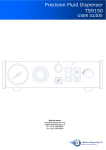
5.2.1 Conexión de la unidad: (Consulte la Figura 4.0)
1. Conecte el cable de alimentación, el interruptor de pedal y la manguera de
aire a la parte posterior de la unidad. Asegúrese de que la presión de la
entrada de aire sea de 70 psi (4,8 barios) o más.
2. Presione el botón de encendido (1) para encender la unidad.
3. Conecte la manguera de aire de la válvula al Puerto A y la manguera de
aire de atomización al Puerto B.
4. Presione el botón de modo (2) y de configuración (3) simultáneamente
hasta que aparezca el texto “SPRAY” (Pulverizador) en la esquina
superior derecha de la pantalla.
Programa No
Modo de ciclo
Tipo de control
P1
Tiempo de
pulveriza
Tiempo de
pulveriza previa
TIMED MODE SPRAY
1
0.100S
A: 70 PSI
0.050S
B: 40 PSI
Contador
Puerto de presión de la válvula
Puerto B de presión
atomizada regulada
Figura 5.0
5.2.2 Selección de programa
Siga los pasos 1 a 4 de la Sección 5.1.2
5.2.3 Configuración del ciclo de dosificación manual/de purga:
Nota: Un ciclo completo de pulverización consiste en: Pulverización
previa, Pulverización y Pulverización posterior
1. Presione el botón de modo (2) hasta que aparezca el texto “PURGE”
(Purgar) en la Pantalla.
2. Mantenga presionado el botón de ajuste (3) durante dos segundos para
ingresar en la pantalla de configuración. Se resaltará el último dígito del
tiempo de Pulverización previa (PRE).
3. Presione el botón (+) o (-) para ajustar el tiempo.
4. Mantenga presionado el botón de ajuste (3) durante dos segundos para
mover el cursor al tiempo de Pulverización posterior (POST).
5. Presione el botón de ajuste (3) para mover el cursor a la siguiente
posición.
6. Presione el botón (+) o (-) para ajustar el tiempo.
7. Mantenga presionado el botón de ajuste (3) durante dos segundos para
guardar los datos.
62
5.5 CYCLE COUNTER (Refer to Figure 9.0)
The cycle counter records the numbers of automatic dispense cycle being
activated. Up to 60,000 cycles can be recorded. To reset the counter, follow
steps below:
1. Press and hold Set button (3) for two seconds to enter setup screen.
2. Press and hold both Set button (3) and Mode button (2) simultaneously to
clear the counter.
3. Press and hold Set button (3) for two seconds to exit setup screen.
Figure 9.0
5.6 TO CHANGE PRESSURE UNIT DISPLAY (Refer to Figure 9.0)
The default pressure unit display is “psi”. To change pressure unit display to
“bar” follow steps below:
1. Press and hold Set button (3) for two seconds to enter setup screen.
2. Press both (+) and (-) button simultaneously two times. The unit “psi” will
be flashing.
3. Press both Set button (3) and (+) button simultaneously to change unit
display to “bar”. Repeat this step to change unit display back to “psi”
4. Press and hold Set button (3) for two seconds to exit setup screen.
5.7 LOW PRESSURE SETTING (Refer to Figure 9.0)
The low-pressure setting is pre-set at the factory to 70 Psi (4.8 bar). When the
supplied pressure drops below 70 Psi (4.8 bar) the unit will not function. To
change the low pressure set point, follow steps below:
1. Set the dispense cycle in “TIMED MODE” mode.
2. Press and hold the Set button (3) for two seconds to enter the setup screen.
3. Press (+) and (-) button simultaneously, the low pressure set point will appear
on display as shown on figure 6.0.
4. Press the Set button (3) and (+) button simultaneously to increase the set point.
5. Press the Set button (3) and (-) button simultaneously to decrease the set point.
6. Press and hold the Set button (3) for two seconds to save the data.
P1 TIMED MODE VALVE
DISP: 0.100 70 psi
Figure 10.0
11
Low pressure
set point