1
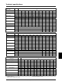
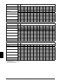
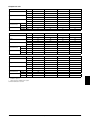
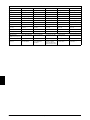
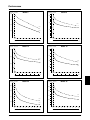
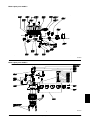
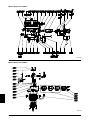
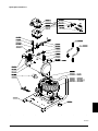
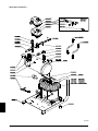
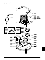
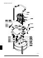
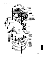
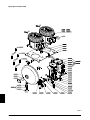
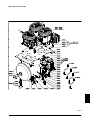
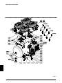
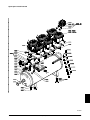
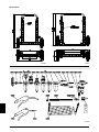
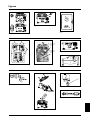
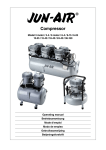
Operating manual 4. Replace the cap on the air intake tube with the intake filter (fig. 2). 5. Connect pneumatic equipment. Information Please note that you can find the pictures and illustrations we are referring to on page 51. Important! The compressor oil may be aggressive towards certain gasket materials used in pneumatic equipment. We recommend Teflon, Viton, etc.. Do not use polycarbonate filter bowls. Contact your local JUN-AIR distributor if you need further information. GB Warning 6. Plug the compressor into an outlet switch of nominal voltage and ensure that fusing is adequate (see Technical Details). · Unless directions are followed and original spare parts used, physical injury or property damage may result. · Protect compressor against rain, moisture, frost, and dust. · Compressor is only suitable for installations with the nomi nal voltage stated on the motor plate. · Do not in any way block or prevent the normal functioning of the safety valve on the receiver. · Only connect pneumatic equipment suitable for the max. pressure indicated. · Do not operate compressor at ambient temperatures exceeding 35°C/95°F or falling below 0°C/32°F. · Do not touch compressor motor during operation as there is a risk of burn due to high temperatures. · Do not direct air flow at head or body. · When a flammable liquid is sprayed, there may be danger of fire or explosion, especially in closed rooms. · Always keep the compressor out of reach of children. 7. Start the compressor using the 0/1 switch on the pressure switch (fig. 3). The compressor will automatically switch off at the preset pressure. If the motor does not start it may be due to pressure in the receiver, and the motor will then start automatically when the pressure reduces to approx. 6 bar/87 psi. 8. Always keep the compressor in a vertical position as oil may run out of the intake filter. During transportation, mount the cap on the inlet. Mechanical noise from the compressor in connection with handling does not have any functional importance. Warning! Never mount the transportation cap on oil-lubricated compressors while there is still pressure in the compressor & pressure vessel, as this may cause a pressure build up in the motor housing. 9. Adjustment of pressure (fig. 4): Guarantee Provided that the operational instructions have been carried out, your JUN-AIR compressor is guaranteed against faulty material or workmanship for 2 years. The air receiver is guaranteed for 5 years. The guarantee does not cover damage caused by violence, misuse, incorrect repairs or use of wrong oil and unoriginal spare parts. Costs of transportation of parts/equipment are not covered by the guarantee. JUN-AIR’s Conditions for Sale and Delivery will generally apply. JUN-AIR International A/S reserves the right to change technical specifications/ constructions. How to operate the JUN-AIR compressor Your JUN-AIR compressor is very easy to operate. Observe the following simple instructions and you will get many years’ service from your compressor. 1. Visually inspect unit for shipping damage, contact your supplier immediately if you think the unit may have been damaged. 2. Always keep the compressor in a vertical position during use and transportation. 3. Place the compressor in a dustfree, dry and cool, yet frostfree, room. Do not install in a closed cupboard, unless adequate openings for ventilation are available (fig. 1). Ensure that the compressor stands firmly on the floor. A: Max. pressure adjustment (cut-out) B: Differential adjustment (cut-in) The cut-in pressure (normally 6 bar) is set by adjustment of differential screw B. Turn clockwise to reduce cut-in pressure. The cut-out pressure is set by even adjustment of the two screws A. (Cut-in pressure + differential = cut-out pressure). Turn clockwise to increase cut-out pressure. The switch is normally factory set for operation at 6-8 bar (approx. 90-120 psi). 10. Adjustment of CONDOR 4-16 press-switch (fig. 4a) The cut-out pressure (normally 16 bar) is set by adjustment of maximum pressure screw. (Cut-in pressure + different pressure = cut-out pressure). Turn clockwise to increase cut-out pressure. The cut-in pressure (normally 14 bar) is set by adjustment of differential screw. Turn clockwise to reduce cut-in pressure. The switch is normally from the factory set for operation at 14-16 bar. Technical details The max. operation of the compressor is 50% of the operation time, and the max. operation time is 15 min. at 8 bar/120 psi in each cycle. Consequently, 15 min. standstill is required before the next start. For tables with technical data and performance curves, see page 23. Operating manual