1
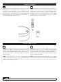
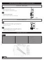
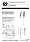
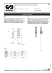
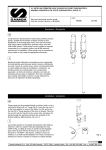
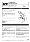
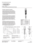
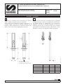
1:1 RATIO AIR OPERATED OIL PUMPS PUMPMASTER 2
BOMBAS NEUMÁTICAS DE ACEITE PUMPMASTER 2, RATIO 1:1
Parts and technical service guide
Guía de servicio técnico y recambio
Part No. / Cód.:
351120 352120
356120
Description / Descripción
E
GB
Compressed air operated piston reciprocating low pressure
pumps. Suitable for high flow transfer of lubricants.
These pumps can be supplied as separate components or as
complete systems with all the elements necessary for its
installation. These pumps may be mounted on mobile units,
drums, tanks or wall, using the appropriate accessories.
Bombas de pistón alternativo accionadas por aire comprimido
de baja presión para el transvase a caudales altos de lubricantes.
Las bombas pueden ser suministradas como componentes
separados o en forma de sistemas completos con todos los
elementos precisos para su instalación. Han sido concebidas
para montaje sobre unidad móvil, bidón, sobre cisterna o mural,
utilizando los accesorios de aspiración de fluido apropiados.
1/4”
B
A
3/4”
2012_04_01-13:50
D
C
Fig. 1
1” (* for 351120 only)
1” (* solo para la bomba 351120)
1” (* uniquement pour pompe 351120)
Model / Modelo
351120
352120
356120
A (mm)
495
1197
1010
B (mm)
282
282
282
C (mm)
52
52
52
D (mm)
213
915
728
Weight / Peso
2,48 kg
5,4 kg
4,80 kg
R. 04/12835 806
1
Samoa Industrial, S.A. · Box 103 Alto Pumarín · 33211 Gijón - Asturias Spain · Tel.: +34 985 381 488 · Fax.: + 34 985 384 163
Installation / Instalación
GB
E
These pumps can be mounted directly on drums, tanks or on a
wall bracket (p.n. 360102) fitted with a 2” bung (Fig 2). Loose
the star nut of the bung adaptor to remove the lower nut , and
screw this into the 2” bung opening of the drum or bracket.
Place the star nut and the split ring on the suction tube. Slide
the pump through the opening and fasten the assemble at the
desired height by tightening the star nut.
Las bombas pueden ser montadas directamente sobre bidones,
cisternas o sobre un soporte mural que dispongan de rosca
2”BSP H (Fig. 2). Aflojar la tuerca en estrella del adaptador para
extraer la parte inferior del mismo y roscarla en el brocal de 2”
del bidón o del soporte. Colocar la tuerca en estrella y el anillo
del adaptador en el tubo, introducir la bomba por el brocal y
apretar el conjunto a la altura deseada.
Fig. 2
Operation / Modo de empleo
E
2012_04_01-13:50
GB
This pump is self–priming. To prime it the first time, you must
connect the air supply to the pump and slowly increase the air
pressure from 0 to the desired pressure using a pressure
regulator, while keeping the outlet valve (ex. an oil control gun)
opened. Once oil starts to come out through the oil gun, the
pump is primed.
Esta bomba es auto-cebante. Para cebarla la primera vez, es
conveniente conectar el aire a la bomba incrementando la
presión lentamente desde 0 bar a la presión deseada con el
regulador de presión, manteniendo la válvula de salida (Ej. una
pistola de aceite) abierta. Cuando el aceite empieza salir de la
pistola, la bomba está cebada.
NOTE: It is important that the foot valve of the pump does not
come into contact with dirty areas, such as a workshop floor,
because it may become contaminated with dirt or foreign
particles that can damage the seals.
NOTA: Es importante que la válvula de pie no esté en contacto
con zonas sucias, tales como el suelo de un taller, porque puede
entrar virutas o partículas que podrían llegar a dañar las juntas
2
835 806 R. 04/12
Samoa Industrial, S.A. · Box 103 Alto Pumarín · 33211 Gijón - Asturias Spain · Tel.: +34 985 381 488 · Fax.: + 34 985 384 163
Typical installation / Conexión tipo de la bomba
GB
E
See figure 3 for a typical installation with all the recommended
accessories for the pump to operate correctly.
GB
NOTA: la presión de alimentación de aire debe estar comprendida
entre 3 y 10 bar siendo 6 bar la presión recomendada. Es
aconsejable instalar, asimismo, una válvula de cierre para poder
cerrar la alimentación de aire al final de la jornada. (En caso de
roturas o fugas en la salida de aceite, si la alimentación de aire no
está cerrada, la bomba se pondría en marcha automáticamente,
pudiendo vaciarse completamente el depósito).
2012_04_01-13:50
NOTE: The compressed air supply must be between 3 and 10 bar
(40 – 140 psi), with 6 bar (90 psi) being the recommended
pressure. An air shut-off valve must be installed, in order to be
able to close the compressed air line at the end of the day. (If the
air inlet not is closed and there is a leakage at some point of the
oil outlet circuit, the pump will start automatically, emptying the
container).
A título informativo, se muestra en la figura 3 una instalación
típica con todos los elementos recomendados para su correcto
funcionamiento.
E
Pos.
Description
Descripción
Part No. / Cód.
A
Air shut-off valve
Válvula de cierre de aire
950319
B
Filter/ Regulator
Filtro Regulador
240500
C
Air hose
Manguera de aire
246010
D
Quick coupling
Enchufe rápido
253114
E
Air nipple
Conector rápido
259014
F
1:1 Pump PM2 (200 l drum)
Bomba PM2 1:1 (Bidón 200 l.)
352120
G
Oil hose
Manguera de aceite
362303
H
High delivery control valve
Boquerel gran caudal
361000
R. 04/12835 806
3
Samoa Industrial, S.A. · Box 103 Alto Pumarín · 33211 Gijón - Asturias Spain · Tel.: +34 985 381 488 · Fax.: + 34 985 384 163
Repair and cleaning procedure / Procedimientos de reparación y limpieza
WARNING
ATENCIÓN
Before starting any kind of maintenance or repair,
disconnect the compressed air supply and
Antes de empezar cualquier tipo de mantenimiento
o reparación, desconecte el aire de alimentación y
open a downstream valve to relieve the oil pressure.
accione la válvula de salida para soltar la presión del aceite.
Air motor / Motor de aire
GB
• Unscrew the suction tube. Be careful not to damage O-Ring
(21).
• Remove pin (14) to separate the lower part of the pump.
14
18
• Remove the screws (20) and pull the air motor dolly to
remove it. The air motor parts will be accesible.
15
16
• Replace (15) and (16) parts if required.
• Clean or replace any damaged part.
E
17
16
• Desenroscar el tubo de succión con cuidado de no dañar la
junta de unión (21).
15
• Quitar el pasador (14) para separar la parte inferior de la
bomba.
15
• Aflojar los tornillos (20) y tirar de la cazoleta hacia arriba de
forma que queden todas las piezas del cuerpo motor de aire
al descubierto.
• Sustituir las piezas (15) y (16) si fuera necesario.
33
19
20
21
• Limpiar o sustituir las piezas deterioradas.
2012_04_01-13:50
Fig. 5
4
835 806 R. 04/12
Samoa Industrial, S.A. · Box 103 Alto Pumarín · 33211 Gijón - Asturias Spain · Tel.: +34 985 381 488 · Fax.: + 34 985 384 163
Repair and cleaning procedure / Procedimientos de reparación y limpieza
Inverter set / Conjunto inversor
GB
Follow the procedures described in the “Air motor” procedure.
Pull the air valve assembly (6).
CAUTION
• The air valve assembly is assembled in a certain position.
Please check the correct position when re-assembling the
pump.
• Attach the shaft (13) to a rubber-covered-clamp vice.
Take out the air pass cap (7) with an Allen key.
CAUTION
• The thread has non-permanent sealant that has to be
applied again when re-assembling the pump. Be careful not
to damage the O-Ring in the air pass cap (7). Parts (9, 10,
11, 12) are ready to be replaced and/or cleaned.
•
E
• Seguir el procedimiento descrito en el apartado “Motor de
Aire” para que el conjunto inversor quede al descubierto.
• Tire de la tulipa superior (6) hacia arriba.
NOTA
• La tulipa superior tiene una posición determinada que
deberá conservarse a la hora de volver a montar la bomba de
nuevo.
5
6
7
8
9
10
11
12
13
Fig. 6
• Fijar el vástago (13) en un tornillo de banco con protección
de goma.
• Sacar el casquillo (7) con ayuda de una llave Allen.
NOTA
• La rosca de fijación tiene sellador desmontable que deberá
ponerse de nuevo a la hora de montar la bomba de nuevo.
2012_04_01-13:50
• Realizar el procedimiento con cuidado de no dañar la junta
que se encuentra en el casquillo (7).
• Las piezas (9, 10, 11, 12) quedarán listas para ser sustituidas
y/o limpiadas
R. 04/12835 806
5
Samoa Industrial, S.A. · Box 103 Alto Pumarín · 33211 Gijón - Asturias Spain · Tel.: +34 985 381 488 · Fax.: + 34 985 384 163
Repair and cleaning procedure / Procedimientos de reparación y limpieza
Pressure valve / Válvula superior
GB
22
• Unscrew the suction tube.
• Unscrew the pressure valve seat (27).
• Clean or replace the valve (25) and ring (26)
24
23
E
25
• Desenroscar el tubo de succión.
• Desenroscar el eje pistón (27).
• Limpiar o sustituir el émbolo (25) y la junta (26).
26
27
Fig. 7
Foot valve / Válvula de pie
GB
30
• Attach the suction tube assemble to a vice and unscrew the
foot valve body from the suction tube. Be careful not to
damage the O ring (30).
28
29
E
31
• Fijar el conjunto tubo de succión en la mordaza y desenroscar
el cuerpo válvula de pie (31) del tubo de succión con
cuidado de no dañar la junta tórica (30).
Fig. 4
Technical data / Datos técnicos
2012_04_01-13:50
GB
E
Maximum air pressure
Presión de aire máxima
10 bar (140 psi)
Minimum air pressure
Presión de aire mínima
3 bar (40 psi)
Maximum delivery
Caudal máximo
52.8 l/min
Air inlet thread
Rosca entrada aire
1/4” NPSM (H) / (F)
Oil inlet thread
Rosca entrada aceite
1” BSP
Oil outlet thread
Rosca salida aceite
3/4” NPSM (H) / (F)
Air piston diameter
Diámetro pistón de aire
50 mm (2”)
6
835 806 R. 04/12
Samoa Industrial, S.A. · Box 103 Alto Pumarín · 33211 Gijón - Asturias Spain · Tel.: +34 985 381 488 · Fax.: + 34 985 384 163
Troubleshooting / Anomalias y sus soluciones
GB
Symptom
Possible cause
Solution
Pump does not start.
No or low air pressure.
Check the air line valve, regulator and
quick coupler.
Motor damaged.
Check air motor mechanism. Check seals
as required and replace any faulty parts.
Air motor blocked by dirt.
As above. Check for free movement and
for foreign objects in piston valve etc.
No oil.
Check oil level in drum/tank.
Pressure valve damaged.
Make sure that pressure valve is free to
move as required.
Foot valve damaged.
Check spring and valve part for correct
operation and seating. Check for foreign
objects jammed in foot valve.
Pump runs irregularly.
Pump cavitation.
Decrease the air pressure in order to reduce the speed.
Oil leak through air muffler.
Fluid packing damaged.
Change the damaged packing.
Pump is running despite the outlet
being closed.
Pressure valve is damaged.
Change the damaged packing.
Dirt in foot valve.
Clean/ check the damaged parts.
Pump reciprocating but not delivering.
Síntomas
Posibles Causas
Soluciones
Bomba parada.
No hay aire de alimentación o la presión de
alimentación es demasiado baja.
Comprobar la línea de aire de alimentación
(incluyendo válvulas, filtros reguladores y
enchufes rápidos).
Motor de aire dañado.
Comprobar y cambiar las partes deterioradas
del mecanismo de motor de aire.
Motor de aire dañado por impurezas.
Comprobar y cambiar las partes deterioradas
del mecanismo de motor de aire.
No hay aceite en el bidón / depósito.
Comprobar el nivel de aceite del bidón /
depósito.
Válvula superior defectuosa o con impurezas.
Comprobar la válvula superior. Limpiarla y/o
cambiar las piezas deterioradas.
Válvula inferior defectuosa o con impurezas.
Comprobar la válvula superior. Limpiarla y/o
cambiar las piezas deterioradas.
La bomba se mueve de forma
irregular.
La bomba está cavitando.
Disminuir la presión del aire de alimentación.
Sale aceite por los silenciosos de
la bomba.
El conjunto empaquetadura de fluido de la
bomba está dañado.
Cambiar el conjunto empaquetadura.
La bomba se mueve aunque la
salida esté cerrada.
Válvula superior defectuosa o con impurezas.
Comprobar la válvula superior. Limpiarla y/o
cambiar las piezas deterioradas.
Válvula inferior defectuosa o con impurezas.
Comprobar la válvula inferior. Limpiarla y/o
cambiar las piezas deterioradas.
La bomba se mueve pero no
entrega aceite.
R. 04/12835 806
7
Samoa Industrial, S.A. · Box 103 Alto Pumarín · 33211 Gijón - Asturias Spain · Tel.: +34 985 381 488 · Fax.: + 34 985 384 163
2012_04_01-13:50
E
Reparation kits / Kits de reparation
GB
E
Repair kit / Kit de reparación
Part No. / Cód.
Pos.
Description
Descripción
735961
1, 2, 3, 4, 35
Muffler and filter kit
Kit silencioso y filtro
735962
10, 15, 16, 21, 26, 30
Air and oil Packing kit
Kit empaquetadura
735963
6, 7, 8, 9, 10, 11, 12
Major repair kit air motor
Kit reparacion motor aire
735966
21, 23, 24, 25, 26, 27
Piston Kit
Kit piston
Only for / Solo para
352120
735964
13, 14, 16, 20, 21, 22, 24
Major repair kit pump tube
Kit reparación tubo
735967
28, 29, 30, 31
Foot valve kit
Kit válvula de pie
Only for / Solo para
351120
735969
13, 14, 16, 20, 21, 22, 24
Major repair kit pump tube
Ki reparación tubo
735970
28, 29, 30, 31
Foot valve kit
Kit válvula de pie
Only for / Solo para
356120
735968
13, 14, 16, 20, 21, 22, 24
Major repair kit pump tube
Kit reparación tubo
735967
28, 29, 30, 31
Foot valve kit
Kit válvula de pie
Repair kit / Kit de reparación
Part No. / Cód.
Pos.
Description
Descripción
735110
5
Air motor dolly
Cazoleta
360001
34
Bung adaptor
Adaptador deslizante
17
Seal corrier
Casquillo
19
Lower body
Cuerpo inferior
860632
18
Seal carrier retaining ring
Guía-tope collarín
2012_04_01-13:50
860631
735114
8
835 806 R. 04/12
Samoa Industrial, S.A. · Box 103 Alto Pumarín · 33211 Gijón - Asturias Spain · Tel.: +34 985 381 488 · Fax.: + 34 985 384 163
Spare parts / Piezas de recambios
Kit nº
735961
1
2
35
3
4
34
Kit nº
735962
18
10
15
16
5
32
17
Kit nº
735963
6
26
30
7
8
16
15
10
735966
33
11
24
15
21
12
19
16
13
20
Kit nº
Kit nº
23
25
26
27
21
Kit nº
735967 (352120) (356120)
735970 (351120)
21
30
22
24
14
28
735964 (352120)
735969 (351120)
735968 (356120)
2012_04_01-13:50
9
29
31
R. 04/12835 806
9
Samoa Industrial, S.A. · Box 103 Alto Pumarín · 33211 Gijón - Asturias Spain · Tel.: +34 985 381 488 · Fax.: + 34 985 384 163
2012_04_01-13:50
Notes / Notas
10 835 806 R. 04/12
Samoa Industrial, S.A. · Box 103 Alto Pumarín · 33211 Gijón - Asturias Spain · Tel.: +34 985 381 488 · Fax.: + 34 985 384 163
2012_04_01-13:50
Notes / Notas
R. 04/12835 806 11
Samoa Industrial, S.A. · Box 103 Alto Pumarín · 33211 Gijón - Asturias Spain · Tel.: +34 985 381 488 · Fax.: + 34 985 384 163
EC conformity declaration / Declaration CE de conformidad
Déclaration CE de conformité / EG-Konformitätserklärung
GB
SAMOA INDUSTRIAL, S.A., Alto de Pumarín, s/n, 33211 - Gijón - Spain, declares that this product conforms with the EU
Directive:
2006/42/EC
E
SAMOA INDUSTRIAL, S.A., Alto de Pumarín, s/n, 33211 - Gijón - España, declara que este producto cumple con la Directiva de
la Unión Europea:
2006/42/CE
F
SAMOA INDUSTRIAL, S.A., Alto de Pumarín, s/n, 33211 - Gijón - Espagne, déclare que ce produit est conforme à la Directive de
l”Union Européenne:
2006/42/CE
D
SAMOA INDUSTRIAL, S.A., Alto de Pumarín, s/n, 33211 - Gijón - Spanien, bestätigt hiermit, dass dieses Produkt der
EG-Richtlinie(n):
2006/42/EG
entspricht.
2012_04_01-13:50
For SAMOA INDUSTRIAL, S.A.
Por SAMOA INDUSTRIAL, S.A.
Pour SAMOA INDUSTRIAL, S.A.
Für SAMOA INDUSTRIAL, S.A.
Pedro E. Prallong Álvarez
Production Director
Director de Producción
Directeur de Production
Produktionsleiter
12 835 806 R. 04/12
Samoa Industrial, S.A. · Box 103 Alto Pumarín · 33211 Gijón - Asturias Spain · Tel.: +34 985 381 488 · Fax.: + 34 985 384 163