1
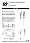
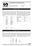
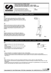
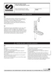
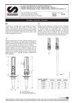
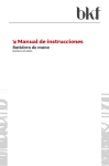
3:1 RATIO AIR OPERATED HIGH VOLUME OIL PUMPS PUMPMASTER 4
BOMBAS NEUMÁTICAS DE ACEITE PUMPMASTER 4, RATIO 3:1
Parts and technical service guide
Guía de servicio técnico y recambio
Cód.:
340120
341120
Description / Descripción
GB
Compressed air operated piston reciprocating medium pressure
pumps. Suitable for the transfer of heavy viscosity oil and
distribution of oil through pipe works, hose reels and meters.
High output allows simultaneous operation when used with
multi outlet systems. These pumps can be supplied as separate
components or as complete systems with all the elements
necessary for its installation. These pumps may be mounted on
drums, tanks or wall, using the appropriate accessories.
E
Bombas de pistón alternativo accionadas por aire comprimido
de media presión para transvasar aceites viscosos o distribución
de aceite a través de conducciones, incluso suministrando fluido
en varias salidas provistas de enrolladores y contadores. Las
bombas pueden ser suministradas como componentes
separados o en forma de sistemas completos con todos los
elementos precisos para su instalación. Han sido concebidas
para montaje sobre bidón, cisterna o mural, utilizando los
accesorios de aspiración de fluido apropiados.
GB
E
Model/
Modelo
A (mm)
B (mm)
C (mm)
D (mm)
Weight/
Peso
340120
341120
585
385
52
200
1295
385
52
910
6.3 Kg
8.3 Kg
3/8”
1/4”
3/4”
C
Ej.
Air pressure: 6 bar
Outlet flow: 20 l/min
Backpressure: 11 bar
Air consuption: 400 l/min
Cycles/min: 215
1”
* for 340120 only
1
Samoa Industrial, S.A. · Box 103 Alto Pumarín · 33211 Gijón - Asturias Spain · Tel.: +34 985 381 488 · Fax.: + 34 985 384 163
R.05/09 834 808
Technical data/ Datos técnicos
Maximum Air pressure
Minimum air pressure
Maximum delivery
Air inlet thread
Oil outlet thread
Air piston diameter
Air piston stroke
Presión de aire máxima
Presión de aire mínima
Caudal máximo
Rosca entrada aire
Rosca salida aceite
Diámetro pistón de aire
Recorrido del pistón de aire
10 bar (140 psi)
3 bar (40 psi)
43 l/min
3/8" (H) / (F)
3/4" (H) / (F)
88 mm (~4”)
75 mm (3”)
Installation / Instalación
GB
E
These pumps can be mounted directly on drums, tanks, or on a
wall bracket fitted with a 2” bung (Fig 2).
•
•
•
Loose the star nut (836150) of the bung adaptor to remove
the inferior nut (736152), and screw this into the 2” bung
opening of the drum or bracket.
Las bombas pueden ser montadas directamente sobre bidones,
cisternas o sobre un soporte mural que dispongan de rosca
2”BSP H (Fig. 2).
•
Afloje la tuerca en estrella (836150) del adaptador para
extraer la parte inferior del mismo (736152) y roscarla en el
brocal de 2” del bidón o del soporte.
Place the star nut (836150) and the ring (836400) on the
suction tube.
•
Coloque la tuerca en estrella (836150) y el anillo (836400)
del adaptador en el tubo
Introduce the pump through the opening and fasten the
assemble at the desired height by tightening the star nut.
•
Introduzca la bomba por el brocal y apriete el conjunto a la
altura deseada.
836150
836400
736152
Fig. 2
2 834808 R.05/09
Samoa Industrial, S.A. · Box 103 Alto Pumarín · 33211 Gijón - Asturias Spain · Tel.: +34 985 381 488 · Fax.: + 34 985 384 163
Installation / Instalación
GB
E
See figure 3 for a typical installation with all the recommended
accessories for the pump to operate correctly.
NOTE: The compressed air supply must be between 3 and 10
bar (40 – 140 psi), being 6 bar (90 psi) recommended pressure.
An air closing valve must be installed, in order to be able to
close the compressed air line at the end of the day (If the air
inlet not is closed and there is a leakage in some point of the oil
outlet circuit, the pump will start automatically, emptying the
container).
A título informativo, se muestra en la figura 3 una instalación típica
con todos los elementos recomendados para su correcto
funcionamiento.
NOTA: La presión de alimentación de aire debe estar comprendida
entre 3 y 10 bares siendo 6 bares la presión recomendada. Es
aconsejable instalar, asimismo, una válvula de cierre para poder
cerrar la alimentación de aire al final de la jornada. (En caso de
roturas o fugas en la salida de aceite, si la alimentación de aire no
está cerrada, la bomba se pondría en marcha automáticamente,
pudiendo vaciarse completamente el depósito).
Fig. 3
Pos
A
B
C
D
E
F
G
H
I
J
K
L
Description
Air closing valve
Filter Regulator
Air hose
Quick coupling
Connection nipple
3:1 Pump PM4 (stubby)
Pressure relieve valve
Oil hose
Oil closing valve
Bung adaptor
Wall bracket
Suction attachment
Descripción
Válvula de cierre de aire
Filtro Regulador
Manguera de aire
Enchufe rápido
Conector rápido
Bomba PM4 3:1 (corta)
Válvula de descarga
Manguera de aceite
Válvula de cierre
de aceite
Adaptador deslizante
Soporte mural
Conjunto de succión
Description
Vanne d’arrêt pour ligne air
Régulateur/filtre
Flexible de liaison air
Raccord rapide
Embout pour raccord rapide
Pompe PM4 3:1 (courte)
Clapet de décharge
Flexible d’huile
Vanne d’arrêt pour circuit
d’huile
Bague de fixation
Support murale
Ensemble d’aspiration
Part Nº
950319
241501
247710
250138
259038
340120
609007
362301
950303
360002
360102
367000
3
Samoa Industrial, S.A. · Box 103 Alto Pumarín · 33211 Gijón - Asturias Spain · Tel.: +34 985 381 488 · Fax.: + 34 985 384 163
R.05/09 834 808
Operation/ Modo de empleo
GB
E
This pump is self–priming. To prime it the first time, you must
connect the air supply to the pump and slowly increase the air
pressure from 0 to the desired pressure using a pressure
regulator, while keeping the outlet valve (ex. an oil control gun)
opened. Once oil starts to come out through the oil gun/ guns,
the pump is primed.
NOTE: It is important that the foot valve does not get in
contact with dirty areas, such as a workshop floor, because it
may enter dirt or foreign particles that can damage the seals.
Esta bomba es auto-cebante. Para cebarla la primera vez, es
conveniente conectar el aire a la bomba incrementando la presión
lentamente desde 0 bares a la presión deseada con el regulador de
presión, manteniendo la válvula de salida (Ej. una pistola de aceite)
abierta. Cuando el aceite empieza salir de la pistola/ las pistolas, la
bomba está cebada.
NOTA: Es importante que la válvula de pie no esté en contacto
con zonas sucias, tales como el suelo de un taller, porque puede
entrar virutas o partículas que podrían llegar a dañar las juntas.
Troubleshooting/ Anomalías y sus soluciones
GB
Symptoms
The pump is not working or there is no
oil delivery.
The pump begins to operate very fast.
The pump keeps on operating although
the oil outlet is closed.
Oil leakage through the air outlet muffler.
Air leakage through the air outlet muffler.
Diminution of the oil delivery.
The pump operates one cycle and stops.
Possible Reasons
Not enough air supply pressure.
Solutions
Increase the air supply pressure.
Some outlet line component is clogged
or closed.
The drum/tank is empty or the oil level is
beneath the suction tube inlet.
Clean or open the outlet circuit.
There is an oil leakage in some point of
the outlet circuit.
Impurities in the upper valve or in the
foot valve (fig. 6-7).
Oil has by-passed to the air motor caused
by worn or damaged packing set (735210).
The piston seal (946503) is worn or damaged.
The air motor dolly is scratched.
The air piston rod (734224) is scratched.
The reversing set (734616) is worn or damaged.
Impurities in the upper valve or in the
foot valve (fig. 6-7).
The top reversing spring (835302) is damaged.
Replace the drum/fill the tank or lower
the suction tube until the inlet reaches
the oil level.
Verify and tighten or repair.
Dismount and clean. Replace in case of
damage.
Replace the packing set (18).
Dismount and clean. Replace in case of
damage.
Replace air motor dolly (1).
Replace the piston rod (9).
Replace the reversing set (4).
Dismount and clean. Replace in case of
damage.
Replace the top reversing spring (2).
E
Síntomas
La bomba no funciona o no hay entrega de aceite.
La bomba empieza a bombear mucho
más deprisa.
La bomba sigue funcionando aunque se
cierre la salida de aceite.
Perdida de aceite por el silenciador del
escape de aire.
Perdida de aire por el silenciador del
escape de aire.
Disminución de caudal entrega de aceite.
La bomba empieza funcionar, pero para
después de un ciclo.
Posibles causas
Presión de suministro de aire no adecuada.
Algún elemento del circuito de salida está
obstruido o cerrado.
El bidón esta vacío o el nivel de la aceite
esta por debajo de la entrada de la bomba.
Existe fuga de aceite en algún punto del
circuito de salida.
Suciedad en la válvula superior o en la
válvula de pie (fig. 6-7).
Aceite ha pasado al motor de aire causado por deterioro del conjunto empaquetadura (735210).
El collarín del vástago (946503) está deteriorado.
La cazoleta del motor de aire está rayada.
El vástago (734224) está rayado.
El conjunto inversor (734616) desgastado.
Suciedad en la válvula superior o en la
válvula de pie (fig. 6-7).
Rotura del muelle inversor superior
(835302).
Soluciones
Incremente la presión de suministro de
aire.
Limpie o abra el circuito de salida.
Sustituir el bidón o calar el tubo de succión hasta llegar al nivel del aceite.
Verificar y apretar o reparar.
Desmontar y limpiar las válvulas. En caso
de deterioro, sustituirlas.
Sustituir el conjunto empaquetadura .
Sustituir el collarín del vástago.
Sustituir la cazoleta.
Sustituir el vástago.
Sustituir el conjunto inversor.
Desmontar y limpiar las válvulas. En caso
de deterioro, sustituirlas.
Sustituir el muelle inversor superior.
4 834808 R.05/09
Samoa Industrial, S.A. · Box 103 Alto Pumarín · 33211 Gijón - Asturias Spain · Tel.: +34 985 381 488 · Fax.: + 34 985 384 163
Repair and cleaning pro c e d u re/ Procedimientos de reparación y limpieza
GB
E
WARNING: Before starting any kind of maintenance or repair,
disconnect the compressed air supply and open a downstream
valve to relieve the oil pressure.
ATENCIÓN: Antes de empezar cualquier tipo de mantenimiento o
reparación, desconecte el aire de alimentación y accione la válvula
de salida para soltar la presión del aceite.
Separate the air motor from the pump/ Como separar el motor de aire de la bomba
GB
E
1. Attach the pump to a vice in horizontal position, grabbing it
by the pump body.
1. Fijar la bomba en una mordaza agarrando por el cuerpo de
la bomba con la bomba en posición horizontal.
2. To unscrew the suction tube (735204-S/735303-) from the
pump body, use a 40 mm wrench on the hexagon of the
foot valve body (835423-S/735306-L) (fig. 4). Pull first
clockwise to break the sealing, and then counter clockwise
to loosen and remove the tube assembly.
2. Para desenroscar el tubo de aspiración (735204-S/735303-L)
del cuerpo de la bomba, usar llave fija de 40 mm en el
cuerpo válvula de pie (835423-S/735306-L) (fig. 4). Tirar
primero contra las agujas del reloj para romper el sellador y
luego hacia el otro sentido para desenroscar y quitar el
conjunto tubo de aspiración.
3. Remove the pin (943041) situated in the upper part of the
connecting rod (735410-S/734504-L) (fig. 5) and unscrew
the rod from the air piston (734224).
3. Extraer el pasador (943041) situado en la parte superior del
eje válvula impulsión (735410-S/734504-L) (Fig. 5) y
desenroscar el eje del vástago (734224).
Fig. 4
Fig. 5
5
Samoa Industrial, S.A. · Box 103 Alto Pumarín · 33211 Gijón - Asturias Spain · Tel.: +34 985 381 488 · Fax.: + 34 985 384 163
R.05/09 834 808
Repair and cleaning pro c e d u re/ Procedimientos de reparación y limpieza
Foot valve/ Válvula de pie
GB
1. Attach the suction tube assembly to the vice and unscrew the
foot valve body (835423-S/735306-L) from the suction tube.
2. Unscrew the nut (941106) and clean the washer (735206) and
the valve body (835423-S/735306-L), replace in case of
damage. Assemble the pump following the previous
instructions, reversing each step.
E
1. Fijar el conjunto tubo de succión en la mordaza y desenroscar
el cuerpo válvula de pie (835423-S/735306-L) del tubo de
succión.
735214
735204
735206
735206
946025
735306
835423
941106
941106
Fig. 6
2. Desenroscar la tuerca (941106) y limpiar la arandela (735206)
y el cuerpo válvula (835423-S/735306-L), en caso de deterioro
sustituirlos. Volver a montar en orden contrario.
Impulsion valve/ Válvula de impulsión
GB
1. Unscrew the valve seat (734205) from the valve body
(734610) and remove the washer (734203), the oil plunger
(946504), the washer (734204), the ball (944152) and the
spring (835300).
2. Clean these parts carefully. In case of damage, replace the
affected parts.
3. Assemble the pump following the previous instructions,
reversing each step.
735410-S
734504-L
943046
734610
E
1. Desenroscar el asiento válvula (734205) del cuerpo válvula
(734610) y quitar la arandela (734203), el collarín (946504), la
arandela (734204), la bola (944152) y el muelle (835300).
734204
946504
2. Limpiar estas piezas cuidadosamente. En caso de deterioro,
sustituir los elementos afectados.
734203
3. Volver a montar en orden contrario.
835300
Fig. 7
944152
734205
6 834808 R.05/09
Samoa Industrial, S.A. · Box 103 Alto Pumarín · 33211 Gijón - Asturias Spain · Tel.: +34 985 381 488 · Fax.: + 34 985 384 163
Repair and cleaning pro c e d u re/ Procedimientos de reparación y limpieza
Packing set/ Conjunto empaquetadura
GB
1. Follow the procedure for the air motor until the air piston
(734224) is outside the air motor body.
2. Remove the circlip (942747) and the packing set (735210)
from the air motor body. Replace in case of damage.
3. Assemble the pump following the previous instructions,
reversing each step.
NOTE: The packing set is directional and must be mounted with
the seals positioned as shown in fig.12.
E
735210
1. Seguir el procedimiento del motor de aire hasta haber extraído
el vástago (734224) del cuerpo motor.
2. Quitar el anillo de seguridad (942747) y el conjunto
empaquetadura (735210) del cuerpo motor de aire. Sustituir
en caso de deterioro.
Fig. 11
942747
3. Volver a montar en orden contrario.
NOTA: El conjunto empaquetadura debe ser montada con las
juntas según fig. 12.
Fig. 12
7
Samoa Industrial, S.A. · Box 103 Alto Pumarín · 33211 Gijón - Asturias Spain · Tel.: +34 985 381 488 · Fax.: + 34 985 384 163
R.05/09 834 808
Repair and cleaning pro c e d u re/ Procedimientos de reparación y limpieza
Inverting set and air motor/ Conjunto inversor y motor de aire
GB
1. Fix the air motor body in a suitable way and unscrew the air
motor screw (940333) then remove it slowly.
835302
2. Check the upper spring (835302) and the spring stop
(735230) inside the air motor dolly (1). Replace in case of
damage.
735230
3. Dismount the lower o-ring (946027) and muffler (860423)
and pull up the inverting set until the hole in pump piston
(734224) gets visible in the opening where the muffler was
dismounted. Introduce a steel rod (8 mm) in the hole to
lock the piston.
E
1. Aflojar los tornillos 940333 y extraer la cazoleta tirando
lentamente hacia arriba.
2. Verificar el muelle superior (835302) y el tope muelle (735230)
en la cazoleta. Sustituir en caso de deterioro.
3. Desmontar la junta tórica inferior (946027) y el silenciador
(860423) y tirar el conjunto inversor hacia arriba hasta que el
agujero en el vástago (734224) quede visible en la apertura
donde el silenciador fue quitado. Introducir una varilla acerada
(8mm) en el agujero del pistón para bloquear el mismo.
734224
940333
946027
860423
Fig. 8
8 834808 R.05/09
Samoa Industrial, S.A. · Box 103 Alto Pumarín · 33211 Gijón - Asturias Spain · Tel.: +34 985 381 488 · Fax.: + 34 985 384 163
Repair and cleaning pro c e d u re/ Procedimientos de reparación y limpieza
Inverting set and air motor/ Conjunto inversor y motor de aire
GB
734616
4. Use a prepared 17mm wrench (see fig. 9) to disassemble
the inverting set (734616).
5. Remove the piston (734224) and disassemble the circlip
(942772), the washer (734612) and the seal (946503)
(fig. 10). Check the piston for scratches and replace
damaged parts.
6. Assemble the pump following the previous instructions,
reversing each step.
E
734224
4. Desenroscar el conjunto inversor (734616) con una llave fija de
17mm preparada (Fig. 9).
5. Quitar el vástago (734224) y desmontar el anillo de seguridad
(942772), la arandela (734612) y el collarín (946503) (Fig. 10).
Verificar que el vástago no esté rayado y sustituir piezas
deterioradas.
Fig. 9
6. Volver a montar en orden contrario.
942772
734612
946503
Fig. 10
9
Samoa Industrial, S.A. · Box 103 Alto Pumarín · 33211 Gijón - Asturias Spain · Tel.: +34 985 381 488 · Fax.: + 34 985 384 163
R.05/09 834 808
Parts drawing/ Dibujo de recambios
836150
836400
946012
942772
834401
736152
734612
835302
946503
735230
735204-S
734616
946148
735303-L
943041
835301
pressure valve
(optional)
834300
940333
609007
735410-S
734504-L
943046
860423
734617
734610
946601
734618
734204
946504
940600
734203
946175
946027
734224
735210
835300
944152
734205
942747
734201-S
734301-L
735214
735206
735214
735206
735306
735304-L
946025
835423
941106
735205-S
941106
10 834808 R.05/09
Samoa Industrial, S.A. · Box 103 Alto Pumarín · 33211 Gijón - Asturias Spain · Tel.: +34 985 381 488 · Fax.: + 34 985 384 163
Repair Kits and spare parts/ Kits de reparación y piezas de recambio
GB
E
Kit number
734953
734963
734955
734964
Part. No incl./Cód. incl.
Description
Muffler and filter kit / Kit silencioso y filtros
834401
Air filter
860423 (x2)
Muffler
946012
O-ring
946027 (x2)
O-ring
Air and oil packing kit / Kit empaquetadura
734612
Support ring
735210
Support packing
942747
Locking ring
942772
Locking ring
943041
Locking pin
943046
Locking pin
946025
O-ring
946148
O-ring
946175
O-ring
946503
U-Packing
946504
U-Packing
Major repair kit air motor / Kit reparación motor de aire
734616
Air piston
734617
Bushing
734618
Bottom plate
735230
Cap
834300
Spring
835301
Spring
835302
Spring
946148
O-ring
Major repair kit central bar / Kit reparación vástago
734224
Central bar
943041
Locking pin
946148
O-ring
946175
O-ring
Option / Opcional:
Kit number
Part. No incl./Cód. incl.
Description
734957
Discharge valve kit / Kit Válvula de descarga
609007
Pressure valve
946601
Bounded seal
Only for / sólo para: 340120
Kit number
Part. No incl./Cód. incl.
Description
734965
Piston kit / Kit pistón (válvula intemedia)
734201
Valve
943041
Locking pin
735205
Foot valve kit / Kit válvula de pie
735206
Flat valve
735214
Axle valve
835423
Seat valve
941106
Nut
946025
O-ring
Only for / sólo para: 341120
Kit number
Part. No incl./Cód. incl.
Description
734966
Piston kit / Kit pistón (válvula intemedia)
734301
Valve
943041
Locking pin
735304
Foot valve kit / Kit válvula de pie
735206
Flat valve
735214
Axle valve
735306
Seat valve
941106
Nut
Descripción
Filtro de aire
Silenciador
Junta tórica
Junta tórica
Porta-stepseal
Anillo de sujección
Anillo de sujección
Manguito de sujección
Manguito de sujección
Junta tórica
Junta tórica
Junta tórica
Collarín
Collarín
Pistón de aire
Casquillo
Tope inferior
Tope goma
Resorte
Resorte
Resorte
Junta tórica
Vástago
Anillo de sujección
Junta tórica
Junta tórica
Descripción
Válvula de presión
Junta metaloplástica
Descripción
Válvula
Anillo de sujección
Válvula plana
Eje válvula
Asiento válvula
Tuerca
Junta tórica
Descripción
Válvula
Anillo de sujección
Válvula plana
Eje válvula
Asiento válvula
Tuerca
11
Samoa Industrial, S.A. · Box 103 Alto Pumarín · 33211 Gijón - Asturias Spain · Tel.: +34 985 381 488 · Fax.: + 34 985 384 163
R.05/09 834 808
EC conformity declaration/ Declaración CE de conformidad/
Déclaration CE de conformité /EG-Konformitätserklärung
GB
SAMOA INDUSTRIAL, S.A., Alto de Pumarín, s/n, 33211 – Gijón – Spain, declares that the product(s):
340120, 341120
conform(s) with the EU Directive(s):
98/37/EC.
E
SAMOA INDUSTRIAL, S.A., Alto de Pumarín, s/n, 33211 – Gijón – España, declara que el(los) producto(s):
340120, 341120
cumple(n) con la(s) Directiva(s) de la Unión Europea:
98/37/CE.
F
SAMOA INDUSTRIAL, S.A., Alto de Pumarín, s/n, 33211 – Gijón – Espagne, déclare que le(s) produit(s):
340120, 341120
est(sont) conforme(s) au(x) Directive(s) de l’Union Européenne:
98/37/CE.
D
SAMOA INDUSTRIAL, S.A., Alto de Pumarín, s/n, 33211 – Gijón – Spanien, bestätigt hiermit, dass das(die) Produkt(e):
340120, 341120
der(den) EG-Richtlinie(n):
98/37/EG
entspricht (entsprechen).
For SAMOA INDUSTRIAL, S.A.
Por SAMOA INDUSTRIAL, S.A.
Pour SAMOA INDUSTRIAL, S.A.
für SAMOA INDUSTRIAL, S.A.
Pedro E. Prallong Álvarez
Production Director
Director de Producción
Directeur de Production
Produktionsleiter
Gijon, Spain, 28 November 2008
12 834808 R.05/09
Samoa Industrial, S.A. · Box 103 Alto Pumarín · 33211 Gijón - Asturias Spain · Tel.: +34 985 381 488 · Fax.: + 34 985 384 163