1
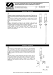
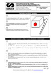
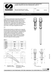
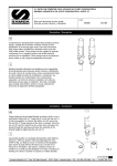
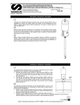
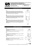
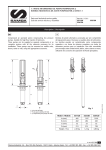
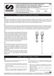
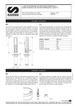
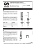
5:1 RATIO AIR OPERATED HEAVY DUTY OIL PUMPS PUMPMASTER 4 BOMBAS NEUMÁTICAS DE ACEITE PUMPMASTER 4, RATIO 5:1 Parts and technical service guide Guía de servicio técnico y recambio Ref.: 400, 406, 408 Description/ Descripción E Compressed air powered reciprocating piston medium pressure pumps. These pumps are suitable for distribution of all types of light and heavy viscosity oil through pipe lines, hose reels and meters. High output allows simultaneous operation when used with multiple outlet systems. These pumps can be supplied as separate components or as complete systems with all the elements necessary for its installation. These pumps may be mounted on drums, tanks or the wall, using the appropriate accessories. SP Bombas de pistón alternativo accionadas por aire comprimido de alta presión para distribución de cualquier tipo de aceite a través de largas conducciones, incluso suministrando fluido en varias salidas provistas de enrolladores y contadores. Las bombas pueden ser suministradas como componentes separados o en forma de sistemas completos con todos los elementos precisos para su instalación. Han sido concebidas para montaje sobre bidón, cisterna o mural, utilizando los accesorios de aspiración de fluido apropiados. Installation/ Instalación E These pumps can be mounted directly on drums, tanks, or on a wall bracket fitted with a 2” bung (Fig 2). Loosen the star nut (1) of the bung adaptor to remove the inferior nut (3), and screw this into the 2” bung opening of the drum or bracket. Place the star nut (1) and the inside part (2) on the suction tube. Introduce the pump through the opening and fasten the assembly at the desired height by tightening the star nut (1). SP Las bombas pueden ser montadas directamente sobre bidones, cisternas o sobre un soporte mural que dispongan de rosca 2”BSP H (Fig. 2). Afloje la tuerca en estrella (1) del adaptador para extraer la parte inferior del mismo (2) y roscarla en el brocal de 2” del bidón o del soporte. Coloque la tuerca en estrella (1) y la mordaza (2) del adaptador en el tubo, introduzca la bomba por el brocal y apriete el conjunto a la altura deseada. Fig. 2 400 Samson Corporation-Swannanoa, NC 28778- 800.311.1047 www.samsoncorporation.com 1 Typical Installation/ Conexión tipo de la bomba E See figure 3 for a typical installation with all the recommended accessories for the pump to operate correctly. NOTE: The compressed air supply must be between 3 and 10 bar (40 – 140 psi), 6 bar (90 psi) is the recommended pressure. An air shut-off valve must be installed, in order to be able to isolate the compressed air line at the end of the day (If the air inlet not is closed and there is a leakage at some point of the downstream oil circuit, the pump will start automatically, emptying the container). SP A título informativo, se muestra en la figura 3 una instalación típica con todos los elementos recomendados para su correcto funcionamiento. NOTA: La presión de alimentación de aire debe estar comprendida entre 3 y 10 bares siendo 6 bares la presión recomendada. Es aconsejable instalar, asimismo, una válvula de cierre para poder cerrar la alimentación de aire al final de la jornada (En caso de roturas o fugas en la salida de aceite, si la alimentación de aire no está cerrada, la bomba se pondría en marcha automáticamente, pudiendo vaciarse completamente el depósito). Fig. 3 Pos Description A B C D E F G H I J Air shut off valve Filter/Regulator Air hose Quick coupler Air nipple 5:1 Pump PM4 (stub) Pressure relief valve Oil hose Oil shut off valve Bung bushing adaptor 400 Descripción Description Válvula de cierre de aire Filtro Regulador Manguera de aire Enchufe rápido Conector rápido Bomba PM4 5:1 (corta) Válvula de descarga Manguera de aceite Válvula de cierre de aceite Adaptador deslizante Valve coupée d'air Régulateur De Filtre Tuyaux d'air Coupleur rapide Mamelon d'air 5:1 Pompe PM4 Valve de décompression Tuyau d'huile Valve coupée d'huile Adapter de douille de bondon 2 Samson Corporation-Swannanoa, NC 28778- 800.311.1047 www.samsoncorporation.com Part Nº 2088 957 822 940 941 400 1063 857 2074 2031 Operation/ Modo de empleo E This pump is self–priming. To prime it the first time, you must connect the air supply to the pump and slowly increase the air pressure from 0 to the desired pressure using a pressure regulator, while keeping the outlet valve (ex. an oil control gun) open. Once oil starts to come out through the oil gun, the pump is primed. NOTE: It is important that the foot valve does not come into contact with any kind of dirt or contamination like a workshop floor, because the dirt will stick to the oil on the pump and may cause subsequent damage to the seals. SP Esta bomba es auto-cebante. Para cebarla la primera vez, es conveniente conectar el aire a la bomba incrementando la presión lentamente desde 0 bares a la presión deseada con el regulador de presión, manteniendo la válvula de salida (Ej. una pistola de aceite) abierta. Cuando el aceite empieza salir de la pistola/ las pistolas, la bomba está cebada. NOTA: Es importante que la válvula de pie no esté en contacto con zonas sucias, tales como el suelo de un taller, porque puede entrar virutas o partículas que podrían llegar a dañar las juntas. Troubleshooting/ Anomalías y sus soluciones Symptoms Possible Reasons The pump is not working or there is no Not enough air supply pressure. oil delivery. Some outlet line component is clogged or closed. The pump runs very fast and no oil is The drum is empty or the oil level is being delivered at the gun. beneath the suction tube inlet. The pump runs on continuously after There is an oil leakage in some point of the oil gun is closed. the outlet circuit. Contamination in the upper valve [(23)(28)] or in the foot valve [(31)-(35)]. Oil is leaking through the exhaust Oil has by-passed to the air motor mufflers. caused by worn or damaged packing set (17). Air is leaking through the exhaust The piston seal (11) is worn or mufflers. damaged. The air motor dolly (1) is scratched. The air piston (8) is scratched. The reversing set (4) is worn or damaged. The oil delivery is less than it used to Contamination in the upper valve [(23)be, or the flow is very uneven. (28)] or in the foot valve [(31)-(35)]. The pump operates only one cycle and The top reversing spring (2) is then stops. damaged. Síntomas Posibles causas La bomba no funciona o no hay entrega Presión de suministro de aire no de aceite. adecuada. Algún elemento del circuito de salida está obstruido o cerrado. La bomba empieza a bombear mucho El bidón esta vacío o el nivel de la más deprisa. aceite esta por debajo de la entrada de la bomba. La bomba sigue funcionando aunque se Existe fuga de aceite en algún punto del cierre la salida de aceite. circuito de salida. Suciedad en la válvula superior [(23)(29)] o en la válvula de pie [(34)-(38)]. Perdida de aceite por el silenciador del Aceite ha pasado al motor de aire escape de aire. causado por deterioro del conjunto empaquetadura (18). Perdida de aire por el silenciador del El collarín del vástago (13) está escape de aire. deteriorado. La cazoleta (1) del motor de aire está rayada. El vástago (9) está rayado. El conjunto inversor (4) desgastado. Disminución del caudal de entrega de Suciedad en la válvula superior [(23)aceite. (29)] o en la válvula de pie [(34)-(38)]. La bomba empieza funcionar, pero para Rotura del muelle inversor superior (2). después de un ciclo. Solutions Increase the air supply pressure. Clean or open the outlet circuit. Replace the drum or lower the suction tube until the inlet reaches the oil level. Verify and tighten or repair. Disassemble and clean. Replace damaged. Replace the packing set (17). if Disassemble and clean. Replace damaged. Replace air motor dolly (1). Replace the air piston (8). Replace the reversing set (4). if Disassemble and clean. Replace if damaged. Replace the top reversing spring (2). Soluciones Incremente la presión de suministro de aire. Limpie o abra el circuito de salida. Sustituir el bidón o calar el tubo de succión hasta llegar al nivel del aceite. Verificar y apretar o reparar. Desmontar y limpiar las válvulas. En caso de deterioro, sustituirlas. Sustituir el conjunto empaquetadura (18). Sustituir el collarín del vástago (13). Sustituir la cazoleta (1). Sustituir el vástago (9). Sustituir el conjunto inversor (4). Desmontar y limpiar las válvulas. En caso de deterioro, sustituirlas. Sustituir el muelle inversor superior (2). 400 Samson Corporation-Swannanoa, NC 28778- 800.311.1047 www.samsoncorporation.com 3 Repair and Cleaning Procedure/ Procedimientos de reparación y limpieza E WARNING: Before starting any kind of maintenance or repair, disconnect the compressed air supply and open a downstream valve to relieve the oil pressure. SP ATENCIÓN: Antes de empezar cualquier tipo de mantenimiento o reparación, desconecte el aire de alimentación y accione la válvula de salida para soltar la presión del aceite. Separate the air motor from the pump/ Como separar el motor de aire de la bomba E 1. 2. 3. 4. Secure the pump in a vice in the horizontal position, tightening the jaws on the provided pads along the pump body (14). Strike the body base gently a few times (31) with a plastic hammer. To unscrew the suction tube (32) from the pump body (14), use a 40 mm wrench on the hex of the foot valve body (37) (fig. 4). Pull clockwise to break the seal, and then counter clockwise to loosen and remove the tube assembly, including the body base (31). Remove the pin (21) located in the upper part of the connecting rod (20) (fig. 5) and unscrew the rod from the air piston (9). SP 1. 2. 3. 4. Fijar la bomba en una mordaza agarrando por el cuerpo de la bomba (14) con la bomba en posición horizontal. Pegar unos golpes con un martillo plástico en la base cuerpo motor aire (31). Para desenroscar el tubo de aspiración (32) del cuerpo de la bomba, usar llave fija de 40 mm en el cuerpo válvula de pie (37) (Fig. 4). Tirar primero contra las agujas del reloj para romper el sellador y luego hacia el otro sentido para desenroscar y quitar el conjunto tubo de aspiración, incluyendo la base (31). Extraer el pasador (21) situado en la parte superior del eje válvula impulsión (20) (Fig. 5) y desenroscar el eje del vástago (9). Fig. 4 Fig. 5 400 4 Samson Corporation-Swannanoa, NC 28778- 800.311.1047 www.samsoncorporation.com Foot valve/ Válvula de pie E 1. 2. Attach the suction tube assembly to the vice (Gently!) and unscrew the foot valve (37) from the suction tube (32). Remove the pin (38) and clean the ball (36), spring (35) and ball seat, and replace if damaged. Assemble the pump following the previous instructions, reversing each step. SP 1. 2. Fijar el conjunto tubo de succión en la mordaza y desenroscar el cuerpo válvula de pie (37) del tubo de succión (32). Quitar el pasador (38) y limpiar la bola (36), el muelle (35) y asiento bola, en caso de deterioro sustituirlos. Volver a montar en orden contrario. Upper valve/ Válvula de impulsión E 1. 2. 3. Unscrew the valve seat (29) from the valve body (23) and remove the washer (28), the oil plunger (27), the washer (26), the ball (25) and the spring (24). Clean these parts carefully. If damaged, replace the affected parts. Assemble the pump following the previous instructions, reversing each step. SP 1. 2. 3. Desenroscar el asiento válvula (29) del cuerpo válvula (23) y quitar la arandela (28), el collarín (27), la arandela (26), la bola (25) y el muelle (24). Limpiar estas piezas cuidadosamente. En caso de deterioro, sustituir los elementos afectados. Volver a montar en orden contrario. Fig. 7 400 Samson Corporation-Swannanoa, NC 28778- 800.311.1047 www.samsoncorporation.com 5 Inverting set and air motor/ Conjunto inversor y motor de aire E 1. 2. 3. 4. 5. 6. SP 1. 2. 3. 4. 5. 6. Secure the air motor body (14) in the vise and unscrew the air motor dolly (1) using a spanner wrench in the holes on the top of the air motor dolly. Check the upper spring (2) and the spring stop (3) inside the air motor dolly (1). Replace if damaged. Remove the lower circlip (15) and muffler (16) and pull up the inverting set (4) until the hole in pump piston (9) is visible in the opening where the muffler was removed. Insert a steel rod (8 mm) in the hole to lock the piston. Use a prepared 17mm wrench (see fig. 9) to disassemble the inverting set (4). Remove the piston (9) and disassemble the circlip (11), the washer (12) and the seal (13) (fig. 10). Check the piston for scratches and replace damaged parts. Assemble the pump following the previous instructions, reversing each step. Use Loctite Blue #242 on the threads of the air-motor stem (5). Fijar el cuerpo motor (14) adecuadamente y desenroscar la cazoleta (1) usando una .. en los agujeros en la parte superior de la cazoleta y quitarla. Verificar el muelle superior (2) y el tope muelle (3) en la cazoleta (1). Sustituir en caso de deterioro. Desmontar el anillo de seguridad (15) inferior y el silenciador (16) y tirar el conjunto inversor hacia arriba hasta que el agujero en el vástago (9) quede visible en la apertura donde el silenciador fue quitado. Introducir una varilla acerada (8mm) en el agujero del pistón para bloquear el mismo. Desenroscar el conjunto inversor (4) con una llave fija de 17mm preparada (Fig. 9). Quitar el vástago (9) y desmontar el anillo de seguridad (11), la arandela (12) y el collarín (13) (Fig. 10). Verificar que el vástago no esté rayado y sustituir piezas deterioradas. Volver a montar en orden contrario. Fig. 9 Fig. 10 400 6 Samson Corporation-Swannanoa, NC 28778- 800.311.1047 www.samsoncorporation.com Packing set/ Conjunto empaquetadura E 1. 2. 3. 4. Follow the procedure for the air motor until the air piston (9) has been removed from the air motor body. Remove the circlip (19) and the packing set (18) from the air motor body (14). Replace if damaged. Assemble the pump following the previous instructions, reversing each step. NOTE: The packing set is directional. It is not marked and must be installed correctly or it will leak. Look carefully at the inside diameter of the seal, you will see three components. The middle black ring that is split is a bearing. Above and below it are the brownish Turcite® seals, these are made with a step, and the step faces the oil. Confirm this by looking into the seal from both directions, from one side you will not see the steps, and from the other you will; this is the side that faces the oil. See Figure 11a. 5. SP 1. 2. 3. Seguir el procedimiento del motor de aire hasta haber extraído el vástago (9) del cuerpo motor. Quitar el anillo de seguridad (19) y el conjunto empaquetadura (18) del cuerpo motor de aire (14). Sustituir en caso de deterioro. Volver a montar en orden contrario. Fig. 11 Fig. 11a 400 Samson Corporation-Swannanoa, NC 28778- 800.311.1047 www.samsoncorporation.com 7 Parts List/ Lista de recambios 400 400 8 Samson Corporation-Swannanoa, NC 28778- 800.311.1047 www.samsoncorporation.com 7 Repair Kits/ Kits de reparación Part. No. AH K1 AH K2 AH K3 FV 51 Description Air Motor Packing Set and Seals Descripción Description Motor de aire Moteur D'Air Conjunto empaquetadura y Ensemble et joints juntas d'emballage Lower End Válvula de impulsión Extrémité Inférieure Foot Valve Válvula De Pie Soupape d'aspiration Parts available separately/ Piezas disponibles por separado 734101 835302 735230 734616 835301 834300 734617 734618 734619 834500 942772 734612 946503 734102 835400 942730 Air Motor Cylinder Upper Spring Spring Button Air Motor Assembly Lower Inner Spring Lower Outer Spring Air Piston Spacer Lower Spring Carrier Piston 5:1 Square Cut Seal Upper Circlip Air Seal Retainer Air Piston Seal Pump Body NPT Muffler Muffler Circlip Not Used 734613 Throat Seal Assembly 942747 735410 943042 943046 734610 835300 944152 734608 946502 734607 734609 946024 734605 734604 2031 946038 835303 944152 734631 943048 Cazoleta Resorte Superior Botón Del Resorte Asamblea De Motor Del Aire Baje El Resorte Interno Baje El Resorte Externo Espaciador Del Pistón Del Aire Baje El Portador Del Resorte Vástago 5:1 Sello Del Corte Del Cuadrado Anillo de retención Superior Detenedor De Sello Del Aire Sello Del Pistón Del Aire Cuerpo De Bomba NPT Silenciador Anillo de retención Del Silenciador Asamblea De Sello De la Garganta Lower Circlip Baje El Anillo de Retención Connecting Rod Biela Upper Roll Pin Perno De Rodillo Superior Lower Roll Pin Perno De una Bobina Más Inferior Oil Plunger Body Cuerpo Del Émbolo Del Aceite Check Spring Compruebe El Resorte Check Ball Compruebe La Bola Upper Seal Retainer Detenedor De Sello Superior Oil Plunger Seal Sello Del Émbolo Del Aceite Lower Seal Retainer Baje El Detenedor De Sello Oil Plunger Base Base Del Émbolo Del Aceite Body Base O-Ring Anillo o Bajo Del Cuerpo Body Base Adapter 5:1 Adaptador Bajo Del Cuerpo 5:1 Suction Tube 5:1 Tubo De la Succión 5:1 Bung Adaptor 5:1 Adaptador deslizante FV O-Ring Anillo o de FV FV Check Spring Resorte Del Cheque de FV Check Ball Compruebe La Bola FV Body Cuerpo de FV FV Roll Pin Perno De Rodillo de FV Include pos. 2-8, 10, 30 10, 11, 13, 18, 19, 21, 22, 27 21-29 34-38 Cylindre De Moteur D'Air Ressort Supérieur Bouton De Ressort Assemblée De Moteur D'Air Abaissez Le Ressort Intérieur Abaissez Le Ressort Externe Entretoise De Piston D'Air Abaissez Le Porteur De Ressort Piston 5:1 Joint De Coupe De Place Circlip Supérieur Arrêtoir De Joint D'Air Joint De Piston D'Air Corps De la Pompe NPT Silencieux Circlip De Silencieux 1 2 3 4 5 6 7 8 9 10 11 12 13 14 15 16 Assemblée De Joint De Gorge 17 18 Abaissez Le Circlip Bielle Goupille De Rouleau Supérieur Goupille De Rouleau Plus Inférieur Corps De Plongeur D'Huile Vérifiez Le Ressort Vérifiez La Boule Arrêtoir De Joint Supérieur Joint De Plongeur D'Huile Abaissez L'Arrêtoir De Joint Base De Plongeur D'Huile Bague Basse De Corps Adapter Bas De Corps 5 :1 Tube D'Aspiration 5 :1 Adapter De Bondon Bague de FV Ressort De Contrôle de FV Vérifiez La Boule Corps de FV Goupille de FV 400 Samson Corporation-Swannanoa, NC 28778- 800.311.1047 www.samsoncorporation.com 19 20 21 22 23 24 25 26 27 28 29 30 31 32 33 34 35 36 37 38 9 Technical Data/ Datos técnicos Maximum Air Pressure Minimum Air Pressure Maximum Delivery Air Inlet Thread Oil Outlet Thread Air Piston Diameter Air Piston Stroke Presión de Aire Máxima Presión de Aire Mínima Caudal Máximo Rosca Entrada Aire Rosca Salida Aceite Diámetro Pistón de Aire Recorrido del Pistón de Aire Pression Atmosphérique Maximum Pression Atmosphérique Minimum La Livraison Maximum Fil D'Entrée D'Air Fil De Sortie D'Huile Diamètre De Piston D'Air Course De Piston D'Air 140 PSI (10 bar) 40 PSI (3 bar) 8 GPM 30 l/min 3/8" NPT (H) / (F) 1" NPT (H) / (F) ~4” (90 mm) 4” (100mm) Dimensions/ Dimenciones Model/ Modelo 400 408 A (mm) IN 28.3 (720) 53.3 (1355) B (mm) IN 17.3 (440) 17.3 (440) C (mm) IN 1.65 (42) 1.65 (42) D (mm) IN 11 (280) 36 (915) Weight LBS Peso(Kg.) 16.3 (7.4) 20.2 (9.2) Fig. 12 400 10 Samson Corporation-Swannanoa, NC 28778- 800.311.1047 www.samsoncorporation.com CAPACITY CURVE CURVE DE CAPACIDAD COURBE DE CAPACITÉ Pump PM 4 5:1 Bomba PM 4 5:1 Pompe PM 4 5/1 Mod. 400 348 100 Technical parameters/ Condiciones técnicas/ Conditions techniques Oil viscosity/ Viscosidad aceite/ Viscosité de l’huile Oil temperature/ Temperatura aceite/ Température de l’huile 1. Air inlet pressure/ Presión entrada aire/ Pression entrée d’air 2. Air inlet pressure/ Presión entrada aire/ Pression entrée d’air 3. Air inlet pressure/ Presión entrada aire/ Pression entrée d’air SAE 30 20ºC (68ºF) 6 bar (84 psi) 4,5 bar (63 psi) 3 bar (42 psi) 400 Samson Corporation-Swannanoa, NC 28778- 800.311.1047 www.samsoncorporation.com 11 Distributed by: 400 12 Samson Corporation-Swannanoa, NC 28778- 800.311.1047 www.samsoncorporation.com FULL SIZE FILTER REGULATOR LUBRICATOR SERIES Parts and Technical Service guide Guía de servicio técnico y recambio Guide d’instructions et pièces de rechange Ref.:Models 970 to 986, 956 to 959 Description/ Descripción/ Description E Full Size Filter Regulator Lubricators perform the important function of reducing air pressure, cleaning the air of particulate contamination and dosing the compressed air with lubricating oil. This series is available as individual components and as combination units. S Filtro Regulador lubricadores desempeñar la importante función de la reducción de la presión del aire, limpiar el aire de partículas de contaminación y la dosificación de aire comprimido con aceite lubricante. Esta serie está disponible en cada uno de los componentes y como combinación de unidades. F Filtre régulateur graisseurs réaliser l'importance de la fonction de réduire la pression de l'air, l'air de nettoyage de la pollution particulaire et de dosage de l'air comprimé avec l'huile de graissage. Cette série est disponible en tant que composants isolés et que la combinaison d'unités. Installation - Operation/ Instalación – Modo de empleo/ Installation – Mode d’emploi E Install the unit using the provided threads. Seal the threads with Loctite® blue #242. Fill the lubricator with 10W non-detergent oil. Adjust the air pressure and lubrication rate as needed. S Instale la unidad usando los hilos de siempre. Selle los hilos con Loctite ® azul # 242. Llenar el lubricador con 10W no detergente petróleo. Ajuste la presión del aire y la tasa de lubricación, según sea necesario. F Installez l'appareil en utilisant les fils fournis. Sceller les fils avec Loctite ® bleu # 242. Remplissez le lubrificateur avec 10W détergent non-huile. Ajustez la pression d'air et de lubrification taux selon les besoins. Technical data/ Datos técnicos Maximum Air Pressure Inlet Threads Outlet Threads Filter Element Regulator Style Temperature Limits Body Material Bowl Material Diaphragm Material Presión de aire máxima Inlet Threads Outlet Threads Elemento filtrante Regulador de Estilo Límites de temperatura Cuerpo Material Material Bowl Material Diafragma Maximum la pression Inlet Threads Fils de liquidation Élément de filtre Style de réglementation Limites de température Matériau du corps Matériel Bowl Diaphragme matières 250 PSI ¼” to ¾” NPTF ¼” to ¾” NPTF 40 Micron Sintered Bronze Self Relieving 40 to 200 Degrees F Die Cast Zinc Aluminum Buna N FRL Samson Corporation-Swannanoa, NC 28778 800-311-1047 www.samsoncorporation.com 1 Troubleshooting/ Anomalías y sus soluciones Symptoms Possible Reasons Air leaks from threads. Assembly/Mounting with thread sealing compounds. Debris in valve. Air leaks from Regulator vent hole. Regulator Adjustment knob not working. No or low Air Flow. Oil exhausts from Lube Pump. Solutions inferior Reseal threads with Loctite Blue #242 or equivalent product. Dissasemble and clean or replace. The flow path is Filter – Regulator – Lubricator. Stripped Replace Regulator Regulator installed backwards Install correctly. Arrow on body indicates flow direction Clogged Filter Clean the brass element Regulator installed backwards Install correctly. Arrow on body indicates flow direction Lubricator adjusted to high Turn the flow down with the adjustment knob. Defective Lube Pump Repair Lube Pump. Reference Table Model 956 957 958 959 970 971 972 973 974 975 976 977 978 980 981 982 983 984 985 986 979 988 990 FRL Description Filter Regulator Filter Regulator Filter Regulator Filter Regulator with 990 Regulator Lubricator Filter Regulator Lubricator Filter Regulator Lubricator Filter Regulator Lubricator Filter Filter Regulator Lubricator Filter Regulator Lubricator Filter Regulator Lubricator Filter Regulator Lubricator Threads ¼” NPTF ⅜” NPTF ½” NPTF ½” NPTF Dimensions 3X3X10 3X3X10 3X3X10 3X3X10 Weight 2 LB 2 LB 2 LB 2 LB Bowl Capacity 5 OZ 5 OZ 5 OZ 5 OZ Max Flow 50 CFM 80 CFM 100 CFM 100 CFM ¼” ¼” ¼” ⅜” ⅜” ⅜” ½” ½” ½” ¾” ¾” ¾” ¼” 3X3X6 3X3X6 3X3X6 3X3X6 3X3X6 3X3X6 3X3X6 3X3X6 3X3X6 3X3X6 3X3X6 3X3X6 9X3X6 1 LB 1 LB 1 LB 1 LB 1 LB 1 LB 1 LB 1 LB 1 LB 1 LB 1 LB 1 LB 3.3 LB N/A 5 OZ 5 OZ N/A 5 OZ 5 OZ N/A 5 OZ 5 OZ N/A 5 OZ 5 OZ 5 OZ X 2 50 CFM 16 CFM 48 CFM 80 CFM 82 CFM 75 CFM 100 CFM 142 CFM 100 CFM 100 CFM 142 CFM 100 CFM 16 CFM ⅜” NPTF 9X3X6 3.3 LB 5 OZ X 2 75 CFM ½” NPTF 9X3X6 3.3 LB 5 OZ X 2 100 CFM ¾” NPTF 9X3X6 3.3 LB 5 OZ X 2 100 CFM 0-160 PSI Gauge Wall Mount Bracket Auto Drain Kit ¼” NPTM N/A N/A N/A NPTF NPTF NPTF NPTF NPTF NPTF NPTF NPTF NPTF NPTF NPTF NPTF NPTF Machine Optional Accessories 2” .3 LB 3X3X½” .3 LB N/A N/A 2X2X2 .3 LB Fits 5 OZ Filters N/A 2 Samson Corporation-Swannanoa, NC 28778 800-311-1047 www.samsoncorporation.com Exploded Drawings FRL Samson Corporation-Swannanoa, NC 28778 800-311-1047 www.samsoncorporation.com 3