1
OPERATION
USING THE CRUISE CONTROL
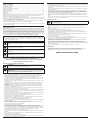
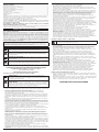
1. Once the engine has been started and warmed up, squeeze
the trigger to accelerate the unit as needed (Fig. 1).
2. For longer periods of operation and to eliminate possible
finger fatigue, move the cruise control toward the
FAST position to incrementally increase or maintain the unit’s
engine speed (Fig. 1). When the cruise control is pressed, the
trigger will recede into the handle.
3. To decrease engine speed, move the cruise control to the
SLOW position and the trigger will return to the idle position
(Fig. 1).
MAINTENANCE
Cruise
Control
FAST
Fig. 1
PUTTING ON THE UNIT
1. Place the shoulder supports over the shoulders so that the
engine rests on the operator’s back.
2. Pull the shoulder support straps down to tighten the shoulder
supports (Fig. 2).
NOTE: The unit must be started prior to putting it on. See Starting/Stopping Instructions.
TAKING OFF THE UNIT
1. Pull up on the bottom tabs of the shoulder support buckles to
loosen the shoulder supports (Fig. 3).
2. Remove the unit.
HOLDING THE BLOWER
Before operating the unit, stand in the operating position and
check for the following (Fig. 4):
• The operator is wearing eye protection and proper clothing.
• If the conditions are dusty, the operator is wearing a dust
mask.
• The unit is secure and comfortable on the operator’s back.
• The right arm is slightly bent and the right hand is gripping the
throttle control.
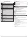
MAINTENANCE SCHEDULE
Perform these required maintenance procedures at the frequency stated in the table. These
procedures should also be a part of any seasonal tune-up.
NOTE: Some maintenance procedures may require special tools or skills. For these types of repairs call 1-800-828-5500 for more information.
NOTE: Please read the California/ EPA statement that came with the unit for a complete listing of terms and coverage for the emissions control devices, such as the spark arrestor, muffler, carburetor, etc
SLOW
Shoulder
Supports
FREQUENCY
Every 10 hours
MAINTENANCE REQUIRED
Clean air filter
SEE
p. 4
Every 25 hours
Check the spark plug condition and gap
p. 4
AIR FILTER MAINTENANCE
WARNING: To avoid serious personal injury, always turn the unit off and allow it to cool
before cleaning or maintaining it.
Fig. 2
Shoulder
Buckles
Fig. 3
OPERATING TIPS
• Never direct the unit at anyone while the unit is in operation.
• Always hold the unit securely when operating.
• To reduce the risk of hearing loss associated with sound
level(s), hearing protection is required.
• Operate power equipment only at reasonable hours. Comply
with times listed in local ordinances. Usual recommendations
are 9:00 am to 5:00 pm, Monday through Saturday.
• To reduce noise levels, operate power blowers at the lowest
possible speed to do the job and limit the total number of
Fig. 4
pieces of power equipment used at any one time.
• Check unit before operating, especially muffler, air intakes and
air filters, for debris and possible blockages.
• Use rakes and brooms to loosen debris before blowing.
• In dusty conditions, slightly dampen surfaces.
• Conserve water by using power blowers instead of hoses for many lawn and garden applications,
including cleaning debri from areas such as screens, patios, grills, porches, and gardens.
• Watch out for children, pets, open windows or freshly washed cars, and blow debris safely away.
• Use the full blower nozzle extension so the air stream can work closer to the ground.
• Clean up after using blowers and other equipment. Dispose of debris appropriately.
• Use the cruise control to make continuous operation easier.
Failure to maintain the air filter properly can result in poor performance or cause permanent damage to
the engine.
Air Filter
Tab
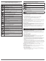
1. Open the air filter cover and remove the air filter (Fig. 5).
Cover
2. Wash the filter in detergent and water. Rinse thoroughly and
allow to dry.
3. Apply clean SAE 30 motor oil to filter.
4. Squeeze filter to spread and remove excess oil.
5. Replace air filter (Fig. 6).
NOTE: Operating unit without air filter WILL VOID warranty.
6. Reinstall the air filter cover and press down until it snaps into
Fig. 5
place (Fig. 5).
ADJUST IDLE SPEED SCREW
The idle speed of the engine is adjustable. An idle adjustment
screw is between the air filter cover and the engine cover (Fig. 7).
NOTE: Careless adjustments can seriously damage your unit. An authorized service dealer should make carburetor adjustments.
If, after checking the fuel and cleaning the air filter, the engine still
will not idle, adjust the idle speed screw as follows:
1. Start the engine and let it run at a high idle for a minute to
warm up. Refer to Starting/Stopping Instructions.
2. Move the cruise control to the SLOW position and let
the engine idle. If the engine stops, insert a small Phillips
screwdriver in between the air filter cover and the engine
cover (Fig. 7). Turn the idle speed screw in, clockwise, 1/8 of a
turn at a time (as needed) until the engine idles smoothly.
Checking the fuel mixture, cleaning the air filter, and adjusting the
idle speed should solve most engine problems. If not and all of the
following are true:
• engine will not idle
• engine hesitates or stalls on acceleration
• there is a loss of engine power
take the unit to a qualified service dealer.
Lock Tabs
Air Filter
Fig. 6
Idle Adjustment
Screw
Fig. 7
REPLACING THE SPARK PLUG
Use a replacement part number 753-06193 or Champion spark plug #RDJ7J. The correct spark gap
is 0.025 in. (0.635 mm).
WARNING: Do not sand blast, scrape or clean spark plug electrodes. Grit in the engine
could damage the cylinder.
APPLICATIONS
• Use the blower for trees, shrubs, flower beds and hard-to-clean areas.
• Use the unit around buildings and for other normal cleaning procedures.
• Use the blower around walls, overhangs, fences and screens.
4
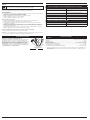
1. Stop the engine and allow it to cool.
2. Grasp plug wire firmly and pull.
3. Clean around spark plug and remove using a 5/8-inch socket
counterclockwise.
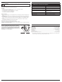
4. Set the air gap, according to specifications, using a feeler
gauge (Fig. 8).
5. Install spark plug turning clockwise and torquing as stated:
• Torque to: 110-120 in.•lb. (12.3-13.5 N•m) Do not over
tighten.
6. Reconnect the spark plug wire.
0.025 in.
(0.635 mm)
Fig. 8