1
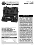
MODEL 4910B
CAPACITY: 10 TON
PORTABLE RAM KIT
PORTABLE HYDRAULIC POWER KIT SETUP INSTRUCTIONS
SETUP
This is the Safety Alert Symbol used for the SETUP INSTRUCTIONS section of this manual to alert you to potential
personal injury hazards. Obey all instructions to avoid possible injury or death.
PLEASE REFER TO THE EXPLODED VIEW DRAWING IN THIS MANUAL IN ORDER TO IDENTIFY PARTS.
1. Refer to the exploded view parts drawing in this manual to identify parts mentioned in this setup procedure.
2. Install the ram at the end of the hose and secure the quick disconnect fittings together by hand tightening the threaded sleeve on
the ram fitting.
3. Insert the pump handle in the pump linkage receiver and rotate the handle clockwise until tight. Before operating the pump, turn the
reservoir vent screw in a counterclockwise direction until it stops.
4. During shipping or handling air may have become trapped in the hydraulic system. If the pump is not providing a full incremental pump
stroke or the ram feels spongy, it will be necessary to purge the air out of the hydraulic system:
a. Before operating the pump, turn the reservoir vent screw in a counterclockwise direction until it stops.
b. Place the pump horizontally on a table. Position the hose and ram over the edge of the table, lower than the pump with the ram piston pointing down.
c. Close the pump’s release valve and pump the ram to its complete or its furthest extension. Open the pump’s release valve to retract the ram all the way. Conduct this procedure several times without a load.
d. If the condition seems better but is still detectable, repeat steps “b” and “c” until all air is purged from the system.
OPERATING INSTRUCTIONS
This is the Safety Alert Symbol used for the OPERATING INSTRUCTIONS section of this manual to alert you to potential
personal injury hazards. Obey all instructions to avoid possible injury or death.
1. Study the work to be done in order to determine the type ram and other attachments you will be using. Consult the enclosed
chart titled “Applicable force for component set ups” in order to determine the maximum allowable force to be used in your
specific setup. All rams have female hose disconnects attached to them, and the end of the hose has the male quick disconnect
attached to it. Insert the male quick disconnect at the end of the hose all the way in to the ram’s female quick disconnect. Slide the
female connector’s threaded sleeve on to the threads of the male connector and hand tighten. Never use any tools to tighten this
connection.
2. Consult this Owner’s Manual section titled APPLICABLE FORCE FOR COMPONENT SET UPS for typical attachment and extension
tube setups and pay very close attention to the corresponding load ratings of certain attachment connections. The use of extension
tubes, ram or plunger toes greatly reduces the hydraulic system’s capacity. When using extension tubes, put the shortest tubes on
the ends of the setup.
3. The pump may be operated in the horizontal or vertical position but the pump must point down when used in the vertical position.
4. Make sure all hydraulic and attachment connections are fully engaged and tight so ram force is straight in order to avoid off-center
load conditions.
5. During setup, make sure the hose routing avoids kinks, twists, curls or bends that will impede hydraulic fluid flow. Do not use the
hose as a means to carry the kit components. Do not subject the hose to any hazards such as fire, extreme heat or cold, sharp
surfaces, or heavy impact. IF A HOSE RUPTURES, BURSTS, OR NEEDS TO BE DISCONNECTED, IMMEDIATELY SHUT THE PUMP
OFF AND OPEN THE RELEASE VALVE TO RELEASE HYDRAULIC PRESSURE. NEVER GRASP A LEAKING PRESSURIZED HOSE,
FITTING OR COMPONENT WITH YOUR HANDS OR SUFFER SERIOUS INJURY.
6. Always use the force gauge to make sure you are within the required force range when operating the system.
7. In order to pump the ram, it will be necessary to turn the release valve knob in a clockwise direction until tight. Tighten by hand only.
8. Pumping the handle up and down transfers the hydraulic fluid from the pump’s reservoir, through the hose, in to the cylinder and
extends the ram with each incremental pump stroke.
9. To release the pressure and return the ram back in to its cylinder, turn the release valve knob in a counterclockwise direction very
slowly. Turning the release valve knob slowly will determine the speed in which the ram will retract back into its cylinder.
IMPORTANT: The pump includes an overload valve that will activate at the pump’s rated capacity only. If the setup requires a reduced rating, the operator is responsible for using the gauge to determine when to stop pumping since the overload valve is set to a
higher rating.
10. Make sure the ram is completely retracted inside its cylinder before disconnecting the hose from the cylinder.
11. The air and hydraulic quick disconnect fittings are repeatedly disconnected and exposed to shop or work place floors that are covered with dirt and debris. It is important to use the dust caps provided to prevent contaminants from entering the air and hydraulic
systems.
12. Based on continuous engagement and disengagement of the hose from the cylinder, eventually it will become necessary to add
hydraulic fluid to the pump’s reservoir. Completely retract the ram before adding hydraulic fluid. Do not overfill in order to avoid
personal injury and hydraulic malfunction. Use only hydraulic jack oil, Chevron Hydraulic Oil AW ISO 32 or its equivalent Unocal Unax
AW 150. Other fluids will cause damage to the hydraulic seals.
4910B 309/29/11