1
EXJRPP
Operating Instructions
Installation Procedures
(continued)
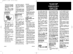
3. Determine the location or layout of other fixtures to
be used with your Rapid Restroom. Tubs, showers, and
sinks will be gravity fed into the tank, so they must be
positioned and installed accordingly (Figure 3).
Hydraulic
Cement
Figure 5: Level tank
6. After the Rapid Restroom is placed in its final
position, test the system before building sub-floors
or attaching fixtures.
a. Using the check valve temporarily connect the
discharge pipe to the house drain.
b. Using the piggyback switch plug, plug the pump
into a GFCI outlet (Figure 6).
Figure 3: Fixture Layout
4. The Rapid Restroom is designed to fit within a 2 in.
x 6 in. floor joist, for built in installations. You may
be able to build a wall between the toilet and the
pump tower, depending on the size of the toilet
(Figure 4).
TEST
T
RESE
GFCI
Outlet
Pump
Power
cord
Piggyback Plug
Figure 6: Grounding plugs
c. Fill the tank with water (Figure 7); the pump
should turn on when the water level reaches
about 4 1/2 in. The closet flange should not fill to
overflowing before the pump turns on.
Water
Hose
Figure 4: Built-in Installation
5. Level the tank to within 1/8 in. for the length and
width of the tank. Do not use wooden shims to level
the tank, use hydraulic cement or similar material
for leveling (Figure 5).
Closet
Flange
Figure 7: Fill Tank
www.waynewatersystems.com
2