1
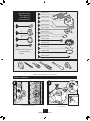
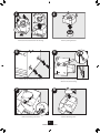
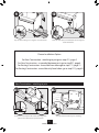
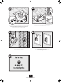
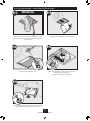
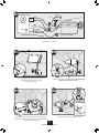
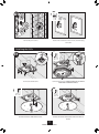
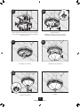
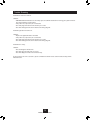
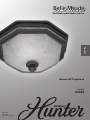
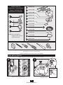
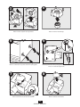
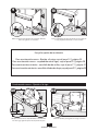
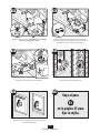
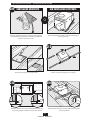
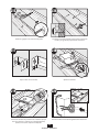
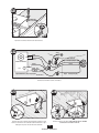
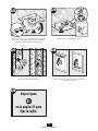
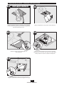
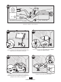
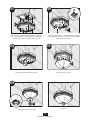
Belle Meade
Bath Ventilator with Light
English
Página 21
Español
Owner’s Manual
Model
82023
42950-01
20110909
©2011 Hunter Fan Co.
1
42950-01 09/09/2011
W
A
R
N
I
N
G
TO REDUCE THE RISK OF ELECTRIC SHOCK OR INJURY, OBSERVE THE FOLLOWING:
1. Use this unit only in a manner intended by the manufacturer. If you have questions, contact the manufacturer at the phone number or address listed in the
warranty.
4. When cutting or drilling into wall(s) or ceiling, do not
damage electrical wiring or other hidden utilities.
5. Ducted fans must always be vented to the outdoors.
Keep ducting as short and as straight as possible.
2. Before installing, servicing, or cleaning the unit,
disconnect the power by turning off the circuit breakers to the outlet box and associated wall switch location. If you cannot lock the circuit breakers in the off
position, securely attach a prominent warning device,
such as a tag, to the service panel.
6. Acceptable for use over a bathtub or shower when
connected to a GFCI protected branch circuit.
7. Install fan at least 5 feet (1.52 m) above the floor.
3. Installation work and electrical wiring must be done
by qualified person(s) in accordance with all applicable
codes and standards, including fire-rated construction
codes and standards.
8. Never place a switch where it can be reached from a
tub or shower.
9. This unit must be grounded.
C AU T I O N
WARNING
1. For general ventilating use only. Do not use for
ventilating hazardous or explosive materials.
DISCONNECT
ELECTRIC
POWER SUPPLY
AND LOCK OUT
SERVICE PANEL
BEFORE
SERVICING UNIT
2. To avoid motor bearing damage and noisy/unbalanced impellers, keep drywall spray, construction
dust, etc. off power unit.
3. DO NOT install this product in a wall. This product is designed for installation in ceilings up to a
12/12 pitch (45 degrees). Ductwork must point
upward.
4. Please read specification label on product for further information and requirements.
PREVENTATIVE MAINTENANCE
A clean fan provides better service. Disconnect the power supply and clean the fan as listed below.
TO CLEAN GRILLE:
Use a mild detergent, such as dishwashing liquid, and a soft cloth. DO NOT use abrasive cloths, steel wool pads
or scouring powders.
TO CLEAN FAN ASSEMBLY: Unplug motor cord from receptacle. To remove motor plate, find the single tab on the
motor plate (located next to the receptacle). Push up rear motor plate tab while pushing out on the side of the
housing or insert a screwdriver into the slot in the housing (next to tab) and twist screwdriver. Gently vacuum
fan, motor and interior of housing.
METAL AND ELECTRICAL PARTS SHOULD NEVER BE IMMERSED IN WATER.
MAINTENANCE
The motor is permanently lubricated and never needs oiling. If the motor bearings are making excessive or
unusual noises, replace the motor with the exact service motor. You should replace the impeller at the same
time.
2
42950-01 09/09/2011
Check all the parts.
If damaged, call
1-888-830-1326
for replacements.
E
F
G
x4
H
A
I
* B
x2 J
3/8” Cable Connector
K
*C
x2
D
L
M
Extra Screws
relief cable connector
* NOTE: Strain
must be installed. Not
Included.
N
O
P
95044-01-096
95029-01-000
77481-01-000
03242-01-232
95491-07-000
65222-01-232
77521-01-000
65219-01-000
97264-01-000
75184-01-092
97266-01-000
76081-01-308
Tools Needed. (Not supplied.)
Before Installation
Estimated assembly time: 30 to 60 minutes
NOTE: Remove all packing materials before installation.
2
1
J
F
Turn off the power source.
Loosen screws.
3
42950-01 09/09/2011
4
3
I
F
Remove packing material.
Remove the motor/blower from the housing.
5
6
Remove the pre-loaded screw tip covers.
Back out the pre-loaded screw tips until flush
with the side of the housing.
7
8
G
H
Remove the wiring cover screw.
Remove the wiring cover.
4
42950-01 09/09/2011
9
10
F
C
B
Pop out the first wiring access slug. Use second if needed.
Insert the strain relief (not included) into the housing and
secure with washer.
Choose Installation Option
For New Construction - attaching to joist go to step A11, page 5
For New Construction - suspended between joists go to step B11, page 8
For Existing Construction - accessible from above go to step C11, page 11
For Existing Construction - accessible only from below go to step D11, page15
New Construction - attaching to joist
A12
A11
F
5/8
1/2
5/8
1/2
Position the correct depth mark at the bottom edge of the
joist based on the thickness of your sheetrock.
Screw pre-loaded screws into joist or framing.
5
42950-01 09/09/2011
A13
Route wires through the strain relief.
A14
Ground
Black
Green
White
A
2 Pin
Fan Motor
3 Pin
Black Main Switch 1 (AC In)
White
White
Light
Bare Copper
Black Light
*Option
Black Switch 2 (AC In)
*Option Fan & Main Light Together
Connect wires as shown.
A15
A16
0
F
H
Install the wiring cover plate. Make sure all
wiring connections are inside the box or under
the wiring cover plate.
6
Connect 4” duct and vent to the outside. Tape joints.
If ducting does not fit securely, an adapter may need
to be purchased.
42950-01 09/09/2011
A17
0
A18 0
I
Reinstall the motor by inserting the tabs and pushing up
into position. Make sure the wires are not pinched
between the motor and the housing.
Connect wiring harness. DO NOT ALLOW THE MOTOR TO
HANG FROM THE WIRING HARNESS.
A19
A20
J
Secure the motor by tightening the 2 screws.
Turn on the power source.
A21
A22
ON
Go to step
E1
on page 17
to attach grille.
OFF
Test the motor. If the motor does not run, check the plug
connection.
7
42950-01 09/09/2011
New Construction – suspended between joists
B12
B11
F
E
5/8
1/2
5/8
1/2
Slide the mounting rails into brackets.
Position the correct depth mark at the bottom edge of
the joist based on the thickness of your sheetrock.
B13
B14
1/8” bit
F
Mark position of screws by using holes as a template.
Drill a hole in the center of each outline.
B16
B15
Insert screws, leaving space between the screw
head and the joist. Screws are not provided.
Attach the rails onto the screws.
8
42950-01 09/09/2011
B17
B18
Tighten screws.
Route wires through the strain relief.
B19
Ground
Black
Green
White
A
2 Pin
Fan Motor
3 Pin
Black Main Switch 1 (AC In)
White
White
Light
Bare Copper
Black Light
*Option
Black Switch 2 (AC In)
*Option Fan & Main Light Together
Connect wires as shown.
B20
H
B21
G
Install the wiring cover plate. Make sure all wiring
connections are inside the box or under the
wiring cover plate.
9
Connect 4” duct and vent to the outside. Tape joints.
If ducting does not fit securely, an adapter may need
to be purchased.
42950-01 09/09/2011
B22
B23
I
I
Reinstall the motor by inserting the tabs and pushing up
into position. Make sure the wires are not pinched
between the motor and the housing.
Connect wiring harness. DO NOT ALLOW THE MOTOR TO
HANG FROM THE WIRING HARNESS.
B25
B24
J
Secure the motor by tightening the 2 screws.
Turn on the power source.
B27
B26
ON
Go to step
E1
on page 17
to attach grille.
OFF
Test the motor. If the motor does not run,
check the plug connection.
10
42950-01 09/09/2011
Existing Construction – accessible from above
C11
EXISTING FAN
NO EXISTING FAN
OR
Remove an existing fan and check to make sure the
opening is large enough to accommodate the new
motor housing (8”x 8 1/2”).
Use the motor housing as a template to mark position.
C12
F
8
8”
1/
2”
E
Cut out an opening for the housing.
Slide the mounting rails into brackets.
C14
C13
5/8
1/2
5/8
1/2
Mark position of screws by using holes as a template.
Position the correct depth mark at the bottom edge of the
joist based on the thickness of your sheetrock.
11
42950-01 09/09/2011
C15
C16
Drill a hole in the center of each outline.
Insert screws, leaving space between the screw head
and the joist. Screws are not provided.
C18
C17
Attach the rails onto the screws.
Tighten screws.
C19
C20
Connect 4” duct and vent to the outside. Tape joints.
If ducting does not fit securely, an adapter may
need to be purchased.
Route wires through the strain relief.
12
42950-01 09/09/2011
C21
Tighten the strain relief screws.
C22
Ground
Black
Green
White
A
2 Pin
Fan Motor
Bare Copper
Black Main Switch 1 (AC In)
White
White
Light
3 Pin
Black Light
*Option
Black Switch 2 (AC In)
*Option Fan & Main Light Together
Connect wires as shown.
C23
C24
G
I
H
Install the wiring cover plate. Make sure all wiring
connections are inside the box or under the
wiring cover plate.
Connect wiring harness. DO NOT ALLOW THE MOTOR TO
HANG FROM THE WIRING HARNESS.
13
42950-01 09/09/2011
C26
C25
J
I
Secure the motor by tightening the 2 screws.
Reinstall the motor by inserting the tabs and pushing up
into position. Make sure the wires are not pinched
between the motor and the housing.
C27
C28
ON
OFF
Test the motor. If the motor does not run,
check the plug connection.
Turn on the power source.
C29
Go to step
E1
on page 17
to attach grille.
14
42950-01 09/09/2011
Existing Construction – accessible only from below
D11
D12
EXISTING FAN
F
Remove an existing fan and check to make sure the opening is large enough to accommodate the new motor housing (8”x 8 1/2”).
Move the housing into position above the ceiling
D13
1
2
D14
Route wires through strain relief.
Attach existing ducting to duct connector. Tape joints.
If ducting does not fit securely,
an adapter may need to be purchased.
D15
F
Install the housing flush with the sheetrock and secure by
tightening the pre-loaded screws into the joist.
15
42950-01 09/09/2011
D16
Ground
Black
Green
White
A
2 Pin
Bare Copper
Black Main Switch 1 (AC In)
Fan Motor
White
White
3 Pin
Light
Black Light
*Option
Black Switch 2 (AC In)
*Option Fan & Main Light Together
Connect wires as shown.
D18
D17
G
I
H
Install the wiring cover plate. Make sure all wiring
connections are inside the box or under
the wiring cover plate.
Connect wiring harness. DO NOT ALLOW THE MOTOR TO
HANG FROM THE WIRING HARNESS.
D20
D19
J
I
Reinstall the motor by inserting the tabs and pushing up
into position. Make sure the wires are not pinched between
the motor and the housing.
Secure the motor by tightening the 2 screws.
16
42950-01 09/09/2011
D22
D21
ON
OFF
Test the motor. If the motor does not run, check the plug
connection.
Turn on the power source.
Attaching the Grille
E2
E1
F
K
N
Remove the thumbscrews.
Connect wiring harness. DO NOT ALLOW THE FIXTURE TO
HANG FROM THE WIRING HARNESS.
E3
E4
J
K
Remove the strain relief bracket screw.
Position the strain relief bracket under the motor as
shown.
17
42950-01 09/09/2011
E5
E6
K
L
Attach thumbscrews.
WARNING: To reduce the risk of electrical shock,
all 4 thumbscrews MUST be properly installed.
Align posts A, B, C and D (stamped into motor housing) with
posts A, B, C and D (stamped into light fixture). Slide light
fixture over posts.
E8
E7
M
Install bulbs (not included).
Align glass dome and push up.
E9
N
Complete.
Screw finial into position.
18
42950-01 09/09/2011
Trouble Shooting
Problem: Fan does not come on.
Solution:
• HUNTER Fan Bath Ventilators are extremely quiet. To confirm that the fan is running, place your hand near
the vents to feel the air movement.
• Turn power on, replace fuse, or reset breaker.
• Check all plug connections to be sure they are secure.
• Check the wiring to make sure it matches the wiring diagram.
Problem: Light does not come on.
Solution:
• Replace the light bulb with a new bulb.
• Turn power on, replace fuse, or reset breaker.
• Check all plug connections to be sure they are secure.
• Check the wiring to make sure it matches the wiring diagram.
Problem: Fan is noisy.
Solution:
• Check and tighten all fasteners.
• Check the glass to make sure it is secure.
• Check the flapper to make sure it moves freely.
If you need parts or service assistance, please call 888-830-1326 or visit us at our web site at http://www.
hunterfan.com.
19
42950-01 09/09/2011
Warranty
Hunter Fan Company
Bath Exhaust Fan
LIMITED WARRANTY
Hunter Fan Company makes the following limited warranty to the original user or consumer purchaser of this Hunter bath
exhaust fan:
If any part of your Hunter bath exhaust fan (except for glass fixtures and light bulbs) fails at any time within one year after
the date of sale to you due to a defect in material or workmanship, we will repair or, at our option, replace the defective part
free of charge for parts and labor performed at our nearest service center or at our Service Department in Memphis, Tennessee. After this one-year period, you will be responsible for all parts and labor costs for repairs on the bath exhaust fan
except for motor repairs as provided below.
If your Hunter bath exhaust fan motor fails at any time within five years after the date of sale to you due to a defect in material or workmanship, labor and materials to repair the defect will be provided free of charge at our nearest service center or
our Service Department in Memphis, Tennessee. If no replacement part can be provided, we will, at our option, either refund the actual purchase price of your bath exhaust fan or provide a replacement free of charge. After this five-year period,
you will be responsible for all parts and labor costs for repairs on all parts of the bath exhaust fan.
IF THE ORIGINAL USER OR CONSUMER PURCHASER CEASES TO OWN THE FAN, THIS WARRANTY AND ANY IMPLIED WARRANTY WHICH THEN REMAINS IN EFFECT, INCLUDING BUT NOT LIMITED TO ANY IMPLIED WARRANTY OF MERCHANTABILITY
OR FITNESS FOR A PARTICULAR PURPOSE, ARE VOIDED. NO WARRANTY, EXPRESS OR IMPLIED, INCLUDING ANY WARRANTY
OF MERCHANTABILITY OR FITNESS FOR A PARTICULAR PURPOSE, IS MADE IN RESPECT OF GLASS FIXTURES OR LIGHT BULBS
OR THE FINISH ON ANY METAL PORTION OF THE BATH EXHAUST FAN.
THIS WARRANTY IS IN LIEU OF ALL OTHER EXPRESS WARRANTIES. THE DURATION OF ANY IMPLIED WARRANTY, INCLUDING, BUT NOT LIMITED TO, ANY IMPLIED WARRANTY OF MERCHANTABILITY OR FITNESS FOR A PARTICULAR PURPOSE, IN
RESPECT TO ANY HUNTER FAN BATH EXHAUST FAN MOTOR OR OTHER FAN PART, IS EXPRESSLY LIMITED TO THE PERIOD OF
THE EXPRESS WARRANTY SET FORTH ABOVE FOR SUCH MOTORS OR OTHER PARTS.
This warranty is voided if your Hunter bath exhaust fan is not purchased and installed in the U.S.A. This warranty excludes
and does not cover defects, malfunctions or failures of any Hunter bath exhaust fan which were caused by repairs by
persons not authorized by us, use of parts or accessories not authorized by us, mishandling, improper installation, modifications or damage to the Hunter bath exhaust fan while in your possession, or unreasonable use, including failure to provide
reasonable and necessary maintenance.
To obtain servicing, contact the nearest Hunter authorized service center of the Hunter Fan Company Service Department,
7130 Goodlett Farms Pkwy Suite 400, Memphis, TN 38016. Please contact us before shipping your bath exhaust fan to us. If
we authorize you to ship it to us, you will be responsible for all insurance and freight or other transportation charges to our
factory or service center. We will return your Hunter bath exhaust fan freight prepaid. Your Hunter bath exhaust fan should
be properly packed to avoid damage in transit since we will not be responsible for any such damage. Proof of purchase is required when requesting warranty service. The purchaser must present the sales receipt or other document that establishes
proof of purchase.
IN NO EVENT SHALL HUNTER FAN COMPANY BE LIABLE FOR CONSEQUENTIAL OR INCIDENTAL DAMAGES.
SOME STATES DO NOT ALLOW LIMITATIONS ON HOW LONG AN IMPLIED WARRANTY LASTS OR THE EXCLUSION OR LIMITATION OF INCIDENTAL OR CONSEQUENTIAL DAMAGES SO THE ABOVE LIMITATION OR EXCLUSIONS MAY NOT APPLY TO YOU.
THE WARRANTY GIVES YOU SPECIFIC LEGAL RIGHTS AND YOU MAY ALSO HAVE OTHER RIGHTS WHICH VARY FROM STATE TO
STATE.
Fan Company
7130 Goodlett Farms Pkwy Suite 400Memphis, TN 38016
20
42950-01 09/09/2011
© 2011 Hunter Fan Company
Belle Meade
Ventilador para baño con luz
Español
Manual del Propietario
Modelo
82023
42950-02
20110909
©2011 Hunter Fan Co.
A
D
V
E
R
T
E
N
C
I
A
PARA REDUCIR EL RIESGO DE DESCARGA ELÉCTRICA O LESIONES, OBSERVE LO SIGUIENTE:
1. Utilice esta unidad sólo de la manera indicada por el fabricante. Si tiene alguna pregunta, contacte con el fabricante en e teléfono o la dirección indicados en la garantía.
2. Antes de instalar, dar servicio o limpiar la unidad,
desconecte la alimentación eléctrica apagando
los interruptores automáticos que alimentan la
caja de salida y al interruptor de pared respectivo.
Si no puede bloquear los interruptores automáticos en la posición de apagado, fije firmemente
una forma destacada de advertencia, como una
etiqueta de seguridad, en el tablero de servicio.
4. Al cortar o taladrar en paredes o techo, no dañe el
cableado eléctrico u otros servicios no visibles.
5. Los ventiladores canalizados siempre deben descargar al aire libre. Mantenga los ductos tan cortos y
rectos como sea posible.
6. Aceptable para uso sobre una bañera o ducha si
se conecta en un circuito derivado protegido por un
interruptor automático de falla a tierra (GFCI).
7. Instale el ventilador por lo menos a 5 pies (1.52 m)
por encima del piso.
3. Los trabajos de instalación y cableado eléctrico
deben ser realizados por personas calificadas
de acuerdo con todos los códigos y las normas
aplicables, incluyendo los códigos y normas de
construcción contra incendio.
8. Nunca coloque un interruptor donde pueda ser
alcanzado desde una tina o una ducha.
9. Esta unidad debe ponerse a tierra.
tc.Retire las cubiertas de las puntas de tornillo precargadas.
PRECAUCIÓN
ADVERTENCIA
1. Sólo para uso de ventilación general. No lo utilice
para ventilar ambientes con materiales peligrosos o
explosivos.
2. Para evitar daños a los rodamientos del motor e
impulsores ruidosos o desbalanceados, mantenga
la unidad de potencia lejos de la aplicación de
aerosol para paneles de yeso (drywall), polvo de
la construcción, etc.
3. NO instale este producto en una pared. Este producto está diseñado para instalarse en techos
con una inclinación de hasta 12/12 (45º). La red
de ductos debe dirigirse hacia arriba.
4. Vea más información y los requisitos en la etiqu- eta de especificación del producto.
DESCONECTE LA
ALIMENTACIÓN
ELÉCTRICA Y
CIERRE EL PANEL
DE SERVICIO
ANTES DE DAR
MANTENIMIENTO
A LA UNIDAD
MANTENIMIENTO PREVENTIVO
Un ventilador limpio proporciona mejor servicio. Desconecte la alimentación y limpie el ventilador como se indica a continuación.
PARA LIMPIAR LA REJILLA: Use un detergente suave, como líquido para lavado de platos, y un paño suave. NO
emplee paños abrasivos, almohadillas de lana de acero ni polvos para fregar.
PARA LIMPIAR EL CONJUNTO DEL VENTILADOR: Desconecte el cordón del motor de la toma de corriente. Para
retirar la placa del motor, encuentre la pestaña en la placa (ubicada junto a la toma de corriente). Levante la
pestaña posterior de la placa del motor mientras empuja hacia afuera en el lado del alojamiento o introduzca un
destornillador en la ranura del alojamiento (junto a la pestaña) y gire el destornillador. Suavemente aspire el ventilador, el motor y el interior del alojamiento.
LAS PARTES METÁLICAS ELÉCTRICAS NUNCA DEBEN SUMERGIRSE EN AGUA.
MANTENIMIENTO
El motor está lubricado permanentemente y no necesita ser engrasado. Si los rodamientos del motor hacen ruidos excesivos o inusuales, reemplace el motor con el motor de servicio exacto. Debe reemplazar el impulsor al
mismo tiempo.
22
42950-02 09/09/2011
Verifique todos los
componentes. Si están dañados,
llame al 1-888-830-1326
para obtener un reemplazo.
E
F
G
x4
H
A
I
* B
J
Conector de cable de 3/8”
K
*C
x2
D
L
M
Tornillos adicionales
N
estar instalado el
* NOTA: Debe
manguito de alivio de tensión
O
del cable. No incluido.
P
95044-01-096
95029-01-000
77481-01-000
03242-01-232
95491-07-000
65222-01-232
77521-01-000
65219-01-000
97264-01-000
75184-01-092
97266-01-000
76081-01-308
Herramientas necesarias (no suministradas)
Tiempo estimado de ensamblaje: entre 30 y 60 minutos
Antes de la instalación
NOTA: Retire todo el material de embalaje antes de la instalación.
2
1
J
F
Apague la fuente de alimentación.
Afloje los tornillos.
23
42950-02 09/09/2011
4
3
I
F
Retire el material de embalaje.
Retire el motor/soplador del alojamiento.
5
6
Retire las cubiertas de las puntas de tornillo precargadas.
Retire las puntas de tornillo precargadas hasta que estén a
nivel con el lado del alojamiento.
7
8
G
H
Retire el tornillo de la cubierta del cableado.
Retire la cubierta del cableado.
24
42950-02 09/09/2011
9
10
F
C
B
Retire el primer tapón metálico de acceso del cableado.
Utilice el segundo si es necesario.
Inserte el manguito de alivio de tensión (no se incluye) en
la caja y sujételo firmemente con una arandela.
Escoja la opción de instalación
Para construcción nueva - fijación a la viga, vaya al paso A11, página 25
Para construcción nueva - suspendido entre vigas, vaya al paso B11, página 28
Para construcción existente - accesible desde arriba, vaya al paso C11, página 31
Para construcción existente - accesible sólo desde abajo, vaya al paso D11, página 35
Construcción nueva – fijación a la viga
A12
A11
F
5/8
1/2
5/8
1/2
Ubique la correcta marca de profundidad en el borde inferior de la viga, según el espesor de su plancha de yeso.
Instale los tornillos precargados en la viga o el marco.
25
42950-02 09/09/2011
A13
Tienda los cables a través del manguito de
alivio de tension.
A14
Tierra
22
pasadores
clavijas
Negro
Verde
Blanco
A
Motor del ventilador
Blanco
Blanco
Luz
33
pasadores
clavijas
Cobre desnudo
Negro Interruptor principal 1 (CA)
Negro Luz
*Opción
Negro Interruptor 2 (CA)
*Opción Ventilador y luz principal juntos
Conecte los alambres como se muestra.
A15
A16
0
F
H
Instale la placa de cubierta del cableado. Asegúrese que
todas las conexiones de cableado estén dentro de la caja o
debajo de la placa de cubierta del cableado.
26
Conecte un ducto de 4” y ventile hacia el exterior. Aplique
cinta a las uniones. Si el ducto no se ajusta firmemente,
puede ser necesario comprar un adaptador.
42950-02 09/09/2011
A17
0
A18 0
I
Vuelva a instalar el motor introduciendo las pestañas y
levantando a su posición. Asegúrese que los alambres no
se pellizquen entre el motor y el alojamiento.
Conecte el mazo de cables. NO PERMITA QUE EL MOTOR
CUELGUE DEL MAZO DE CABLES.
A19
A20
J
Encienda la fuente de alimentación.
Asegure el motor apretando los 2 tornillos.
A21
A22
Vaya al paso
ENCE
NDIDO
E1
en la página 37 para
fijar la rejilla.
APAG
ADO
Pruebe el motor. Si el motor no funciona, verifique la
conexión del enchufe.
27
42950-02 09/09/2011
Construcción nueva – suspendido entre vigas
B12
B11
F
E
5/8
1/2
5/8
1/2
Deslice los rieles de montaje en los soportes.
Ubique la correcta marca de profundidad en el borde
inferior de la viga, según el espesor de su plancha de yeso.
B13
B14
broca de
1/8 de pulg.
F
Marque la posición de los tornillos utilizando los agujeros
como una plantilla.
Taladre un agujero en el centro de cada perfil.
B16
B15
Introduzca los tornillos, dejando espacio entre la cabeza del
tornillo y la viga. No se proporcionan los tornillos.
Fije los rieles con los tornillos.
28
42950-02 09/09/2011
B17
B18
Apriete los tornillos.
Tienda los cables a través del manguito de
alivio de tension.
B19
Tierra
22
pasadores
clavijas
Negro
Verde
Blanco
A
Motor del ventilador
33
pasadores
clavijas
Negro Interruptor principal 1 (CA)
Blanco
Blanco
Luz
Cobre desnudo
Negro Luz
*Opción
Negro Interruptor 2 (CA)
*Opción Ventilador y luz principal juntos
Conecte los alambres como se muestra.
B20
H
B21
G
Instale la placa de cubierta del cableado. Asegúrese que
todas las conexiones de cableado estén dentro de la caja o
debajo de la placa de cubierta del cableado.
29
Conecte un ducto de 4” y ventile hacia el exterior. Aplique
cinta a las uniones. Si el ducto no se ajusta firmemente,
puede ser necesario comprar un adaptador.
42950-02 09/09/2011
B22
B23
I
I
Vuelva a instalar el motor introduciendo las pestañas y
levantando a su posición. Asegúrese que los alambres no
se pellizquen entre el motor y el alojamiento.
Conecte el mazo de cables. NO PERMITA QUE EL MOTOR
CUELGUE DEL MAZO DE CABLES.
B25
B24
J
Asegure el motor apretando los 2 tornillos.
Encienda la fuente de alimentación.
B27
B26
Vaya al paso
ENCE
NDIDO
E1
en la página 37 para
fijar la rejilla.
APAG
ADO
Pruebe el motor. Si el motor no funciona, verifique la
conexión del enchufe.
30
42950-02 09/09/2011
Construcción existente – accesible desde arriba
C11
VENTILADOR EXISTENTE
SIN VENTILADOR EXISTENTE
O
Retire el ventilador existente y asegúrese que la abertura
sea suficientemente grande para acomodar el alojamiento
del motor nuevo (8” x 8 1/2”).
Utilice el alojamiento del motor como una plantilla para
marcar la posición.
C12
F
8
8”
1/
2”
E
Recorte una abertura para el alojamiento.
Deslice los rieles de montaje en los soportes.
C14
C13
5/8
1/2
5/8
1/2
Marque la posición de los tornillos utilizando los agujeros
como una plantilla.
Ubique la correcta marca de profundidad en el borde inferior de la viga, según el espesor de su plancha de yeso.
31
42950-02 09/09/2011
C15
C16
Taladre un agujero en el centro de cada perfil.
Introduzca los tornillos, dejando espacio entre la cabeza del
tornillo y la viga. No se proporcionan los tornillos.
C18
C17
Fije los rieles con los tornillos.
Apriete los tornillos.
C19
C20
Conecte un ducto de 4” y ventile hacia el exterior. Aplique
cinta a las uniones. Si el ducto no se ajusta firmemente,
puede ser necesario comprar un adaptador.
Tienda los cables a través del manguito de alivio de tension.
32
42950-02 09/09/2011
C21
Apriete los tornillos del aliviador de tensiones.
C22
Tierra
22
pasadores
clavijas
Negro
Verde
Blanco
A
Motor del ventilador
Cobre desnudo
Negro Interruptor principal 1 (CA)
Blanco
Blanco
Luz
33
pasadores
clavijas
Negro Luz
*Opción
Negro Interruptor 2 (CA)
*Opción Ventilador y luz principal juntos
Conecte los alambres como se muestra.
C23
C24
G
I
H
Instale la placa de cubierta del cableado. Asegúrese que
todas las conexiones de cableado estén dentro de la caja o
debajo de la placa de cubierta del cableado.
Conecte el mazo de cables. NO PERMITA QUE EL MOTOR
CUELGUE DEL MAZO DE CABLES.
33
42950-02 09/09/2011
C26
C25
J
I
Asegure el motor apretando los 2 tornillos.
Vuelva a instalar el motor introduciendo las pestañas y
levantando a su posición. Asegúrese que los alambres no
se pellizquen entre el motor y el alojamiento.
C27
C28
ENCE
NDIDO
APAG
ADO
Pruebe el motor. Si el motor no funciona, verifique la
conexión del enchufe.
Encienda la fuente de alimentación.
C29
Vaya al paso
E1
en la página 37 para
fijar la rejilla.
34
42950-02 09/09/2011
Construcción existente – accesible sólo desde abajo
D11
D12
VENTILADOR EXISTENTE
F
Retire el ventilador existente y asegúrese que la abertura
sea suficientemente grande para acomodar el alojamiento
del motor nuevo (8” x 8 1/2”).
Mueva el alojamiento a su posición encima del techo.
D13
1
2
D14
Tienda los cables a través del manguito de
alivio de tension.
Conecte el ducto existente con el conector de ducto.
Aplique cinta a las uniones. Si el ducto no se ajusta firmemente, puede ser necesario comprar un adaptador.
D15
F
Instale el alojamiento a nivel con la plancha de yeso y
asegúrelo apretando los tornillos precargados en la viga.
35
42950-02 09/09/2011
D16
Tierra
22
pasadores
clavijas
Negro
Verde
Blanco
A
Cobre desnudo
Negro Interruptor principal 1 (CA)
Motor del ventilador
Blanco
Blanco
Luz
33
pasadores
clavijas
Negro Luz
*Opción
Negro Interruptor 2 (CA)
*Opción Ventilador y luz principal juntos
Conecte los alambres como se muestra.
D18
D17
G
I
H
Instale la placa de cubierta del cableado. Asegúrese que
todas las conexiones de cableado estén dentro de la caja o
debajo de la placa de cubierta del cableado.
Conecte el mazo de cables. NO PERMITA QUE EL MOTOR
CUELGUE DEL MAZO DE CABLES.
D20
D19
J
I
Vuelva a instalar el motor introduciendo las pestañas y
levantando a su posición. Asegúrese que los alambres no se
pellizquen entre el motor y el alojamiento.
Asegure el motor apretando los 2 tornillos.
36
42950-02 09/09/2011
D22
D21
ENCE
NDIDO
APAG
ADO
Pruebe el motor. Si el motor no funciona, verifique la
conexión del enchufe.
Encienda la fuente de alimentación.
Fijación de la rejilla
E2
E1
F
K
N
Retire los tornillos de mano.
Conecte el mazo de cables. NO PERMITA QUE EL ARTEFACTO
DE ILUMINACIÓN CUELGUE DEL MAZO DE CABLES.
E3
E4
J
K
Retire el tornillo del soporte del aliviador de tensiones.
Coloque el soporte del aliviador de tensiones (3)
debajo del motor como se muestra.
37
42950-02 09/09/2011
E6
E5
K
L
Instale los tornillos de mano. ADVERTENCIA: Para reducir el
riesgo de descarga eléctrica, los 4 tornillos de mano DEBEN
instalarse apropiadamente.
Alinee los postes A, B, C y D (estampados en la caja del motor) con los postes A, B, C y D (estampados en el artefacto
de iluminación). Deslice la lámpara sobre los postes.
E8
E7
M
Instale la lámpara fluorescente (incluida).
Alinee la pantalla y levante.
E9
N
Complete.
Enrosque la cubierta ornamental.
38
42950-02 09/09/2011
Solución de problemas
Problema: El ventilador no está operando.
Solución:
• Los ventiladores de baño Hunter son muy silenciosos. Para confirmar que el ventilador esté funcionando,
coloque su mano cerca de los conductos de ventilación para sentir el movimiento del aire.
• Encienda la alimentación eléctrica, reemplace el fusible o restablezca el interruptor automático.
• Verifique todas las conexiones de los enchufes para asegurarse que estén firmes.
• Verifique el cableado para asegurarse que coincida con el diagrama de cableado.
Problema: La luz no funciona.
Solución:
• Reemplace la bombilla con una nueva.
• Encienda la alimentación eléctrica, reemplace el fusible o restablezca el interruptor automático.
• Verifique todas las conexiones de los enchufes para asegurarse que estén firmes.
• Verifique el cableado para asegurarse que coincida con el diagrama de cableado.
Problema: El ventilador hace ruido.
Solución:
• Verifique y apriete todos los pernos y tornillos.
• Verifique la pantalla para asegurarse que esté firme.
• Verifique la clapeta para asegurarse que se mueva con libertad.
Si necesita repuestos o servicio, llame al 888-830-1326 o visite nuestro sitio web en http://www.hunterfan.com.
39
42950-02 09/09/2011
Garantía
Hunter Fan Company
Extractor de aire para baño
GARANTÍA LIMITADA
Hunter Fan Company establece la siguiente garantía limitada al usuario o comprador original de este Extractor de aire para
baño Hunter:
Si alguna pieza de su Extractor de aire para baño Hunter (con excepción de las lámparas de vidrio y las bombillas) falla en
cualquier momento dentro de un año después de la fecha de compra debido a una falla de material o mano de obra, repararemos o, a nuestra elección, reemplazaremos la pieza defectuosa sin costo de partes y mano de obra realizada en nuestro
centro de reparaciones más cercano o en nuestro Departamento de servicio en Memphis, Tennessee. Después de este
período de un año, usted será responsable de todos los costos de partes y mano de obra para reparaciones del Extractor de
aire para baño, con excepción de reparaciones del motor, como se estipula a continuación.
Si el motor de su Extractor de aire para baño Hunter falla en cualquier momento dentro de cinco años después de la fecha
de compra debido a una falla de material o mano de obra, la mano de obra y los materiales para reparar la falla serán proporcionados sin costo en nuestro centro de reparaciones más cercano o en nuestro Departamento de servicio en Memphis,
Tennessee. Si no puede proporcionarse alguna parte de reemplazo, a nuestra elección, le reembolsaremos el precio de
compra real de su Extractor de aire para baño o le proporcionamos uno de reemplazo sin costo. Después de este período de
cinco años, usted será responsable de todos los costos de partes y mano de obra para reparaciones de cualquier componente del Extractor de aire para baño.
SI EL USUARIO O COMPRADOR ORIGINAL DEJA DE POSEER EL EXTRACTOR DE AIRE, ESTA GARANTÍA Y CUALQUIER GARANTÍA IMPLÍCITA QUE PERMANEZCA EN EFECTO, INCLUYENDO PERO SIN LIMITARSE A TODA GARANTÍA IMPLÍCITA DE
COMERCIABILIDAD OIDONEIDAD PARA UN PROPÓSITO PARTICULAR, QUEDA ANULADA. NO SE OFRECE NINGUNA GARANTÍA EXPRESA O IMPLÍCITA, INCLUYENDO CUALQUIER GARANTÍA DE COMERCIABILIDAD O IDONEIDAD PARA UN PROPÓSITO
PARTICULAR, PARA LAS LÁMPARAS DE VIDRIO O LAS BOMBILLAS O EL ACABADO DE CUALQUIER PARTE METÁLICA DEL
EXTRACTOR DE AIRE PARA BAÑO.
ESTA GARANTÍA SUSTITUYE A TODAS LAS OTRAS GARANTÍAS EXPRESAS. LA DURACIÓN DE TODA GARANTÍA IMPLÍCITA, INCLUYENDO PERO SIN LIMITARSE A CUALQUIER GARANTÍA IMPLÍCITA DE COMERCIABILIDAD O IDONEIDAD PARA UN PROPÓSITO
PARTICULAR, CON RESPECTO DE CUALQUIER MOTOR DE EXTRACTOR DE AIRE PARA BAÑO HUNTER U OTRA PARTE DEL
VENTILADOR, ESTÁ EXPRESAMENTE LIMITADA AL PERIODO DE LA GARANTIA EXPRESA ESTABLECIDA ANTERIORMENTE PARA
DICHOS MOTORES U OTRAS PARTES.
Esta garantía es nula si su Extractor de aire para baño no se adquiere e instala en los EE.UU. Esta garantía excluye y no cubre
defectos, averías o fallas del Extractor de aire para baño Hunter que fueran ocasionados por reparaciones por parte de personas no autorizadas por nosotros, por el uso de piezas o accesorios no autorizados por nosotros, por mal uso, modificaciones,
o daños al Extractor de aire para baño Hunter mientras esté en su posesión, o por un empleo no razonable, incluyendo la
falta de suministrar un razonable y necesario mantenimiento.
Para obtener servicio, contacte con el centro de servicio autorizado Hunter más cercano o con nuestro Departamento de
servicio de Hunter Fan Company, en 7130 Goodlett Farms Pkwy Suite 400, Memphis, TN 38016. Le agradeceremos que se
ponga en contacto con nosotros antes de enviarnos su Extractor de aire para baño. Si le autorizamos a enviarlo, usted será
responsable de todos los cargos de seguro y flete o de otras cargas del transporte a nuestra planta o centro de reparaciones. Devolveremos su Extractor de aire para baño Hunter con el flete prepagado. Su Extractor de aire para baño Hunter se
debe embalar apropiadamente para evitar daños durante el tránsito ya que no seremos responsables de dichos daños. Al
solicitar un servicio de garantía, debe exhibir una prueba de su compra. El comprador debe presentar el recibo de compra u
otro documento que establezca la prueba de su compra.
EN NINGÚN CASO HUNTER FAN COMPANY SERÁ RESPONSABLE DE DAÑOS PERJUDICIALES O ACCESORIOS.
ALGUNOS ESTADOS NO PERMITEN LIMITACIONES SOBRE LA DURACIÓN DE UNA GARANTÍA IMPLÍCITA O LA EXCLUSIÓN O
LIMITACIÓN DE DAÑOS ACCESORIOS O PERJUDICIALES, POR LO QUE LA LIMITACIÓN O EXCLUSIONES ANTES MENCIONADAS PUEDEN NO APLICARSE A USTED.
LA GARANTÍA LE DA DERECHOS LEGALES ESPECÍFICOS, PERO USTED TAMBIÉN PUEDE TENER OTROS DERECHOS QUE
VARÍAN DE ESTADO A ESTADO.
Fan Company
7130 Goodlett Farms Pkwy Suite 400
Memphis, TN 38016
40
42950-02 09/09/2011
© 2011 Hunter Fan Company