1
Service
Using an HVLP Spray Gun
Should your HVLP spray gun need service during the warranty
period, return the unit and the proof of purchase to the distributor
where it was purchased. At our option, the unit will be repaired
or replaced. In a continued commitment to improve quality, we
reserve the right to make component or design changes when
necessary.
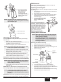
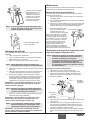
Preparing to Spray
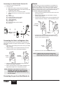
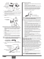
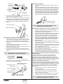
1. Release the cup locking lever and remove the cup.
2. Make sure that the cup and the cup gasket is clean and in
position. Fill the cup with the desired painting material.
3. Place the cup on the spray gun and tighten the cup locking
lever.
4. Attach the air supply hose to the air inlet fitting at the
bottom of the gun handle.
5. Turn on the air supply.
Introduction
These spray guns are designed for use in a High Volume/Low
Pressure (HVLP) painting system.
With an HVLP system, the highest quality professional finish can
be achieved with little preparation or setup time. HVLP systems
are not intended to replace airless systems. Instead, they are
meant to compliment airless by improving the final finish on the
substrate, minimizing waste, and reducing labor time. In addition
to enhancing profitability, HVLP systems are compliant with the
most stringent transfer efficiency requirements.
The HVLP spray guns described in this manual include the
turbine cup gun, the turbine regulator gun, the turbine top feed
gun, the regulator cup gun, and the regulator top feed gun.
Please review all the information contained in this manual before
operating an HVLP system.
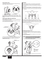
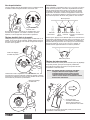
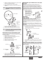
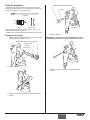
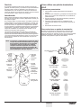
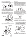
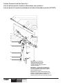
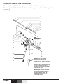
Selecting a Spray Pattern
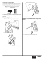
The spray pattern is adjusted by turning the air cap into either
a vertical, horizontal, or diagonal position. To turn the air cap,
grasp the two front tabs and twist. Never trigger the gun while
adjusting the spray pattern.
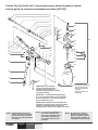
NOTE: The general operation and maintenance of each
style of HVLP spray gun are the same. For
illustration purposes, the turbine cup gun is
pictured. However, any information specific to
a style of gun is described where necessary. A
parts listing for each style of gun is included near
the back of this manual.
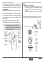
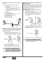
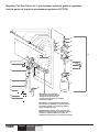
Air Flow
Adj. Knob
Material Flow
Adj. Knob
Packing Nut
Trigger
Check Valve
Air Cap Tabs
Air Cap Ring
Air Cap
Vertical
Tip Position
Fluid Inlet
Cup Locking
Lever
1-Quart Cup
Assembly
Air Inlet
Swivel Tube
Lever
© Titan Tool Inc. All rights reserved.
Horizontal
Pattern
3
Diagonal
Tip Position
Round
Pattern
Horizontal
Tip Position
Vertical
Pattern
English