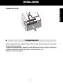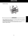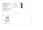
1
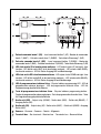
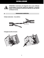
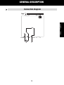
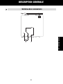
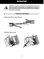
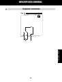
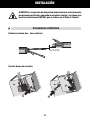
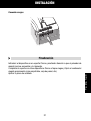
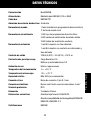
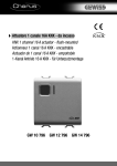
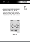
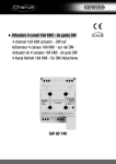
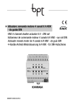
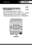
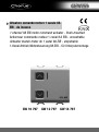
Attuatore comando motore 1 canale 8A
EIB - da incasso
1 channel 8A EIB motor command actuator - flush-mounted
Actionneur commande moteur 1 canal 8 A EIB - encastrable
Actuador mando motor de 1 canal 8A EIB - empotrable
1-Kanal Antrieb Motorsteuerung 8A EIB - für Unterputzmontage
GW 10 797 GW 12 797 GW 14 797
1
3
2
4
5
6
7
8
9
10
1
Pulsante comando locale 1 (SU) - Local command button 1 (UP) - Bouton de commande
locale 1 (HAUT) - Pulsador mando local 1 (SUBIR) - Taste lokale Steuerung 1 (AUF)
2
Pulsante comando locale 2 (GIÙ) - Local command button 2 (DOWN) - Bouton de
commande locale 2 (BAS) - Pulsador mando local 2 (BAJAR) - Taste lokale Steuerung 2 (AB)
3
LED stato uscita SU e localizzazione notturna - LED output status UP and night -time
location - LED d’état sortie HAUT et de localisation nocturne - LED estado salida SUBIR y
localización nocturna - LED für Status Ausgang AUF und Nachtanzeige
4
LED stato uscita GIÙ e localizzazione notturna - LED output status DOWN and night -time
location - LED d’état sortie BAS et de localisation nocturne - LED estado salida BAJAR y
localización nocturna - LED für Status Ausgang AB und Nachtanzeige
5
LED di programmazione indirizzo fisico - Physical address programming LED - LED de
programmation adresse physique - LED de programación dirección física - LED für
Programmierung physikalische Adresse
6
Tasto di programmazione indirizzo fisico - Physical address programming button Touche de programmation adresse physique -Tecla de programación dirección física - Taste
für Programmierung physikalische Adresse
7
Uscita relè (GIÙ) - Output relay (DOWN) - Sortie relais (BAS) - Salida relé (BAJAR) - 7
Ausgang Relais (AB)
8
Uscita relè (SU) - Output relay (UP) - Sortie relais (HAUT) - Salida relé (SUBIR) - Ausgang
Relais (AUF)
9
Comune - Common - Commun - Común - Allgemein
10 Terminali bus - Bus terminals - Borniers bus - Terminales bus - Busanschlüsse
INDICE
pag.
DESCRIZIONE GENERALE .....................................................................................
4
INSTALLAZIONE....................................................................................................
6
PROGRAMMAZIONE CON SOFTWARE ETS ...........................................................
8
DATI TECNICI ........................................................................................................
9
3
I
T
A
L
I
A
N
O
DESCRIZIONE GENERALE
L’Attuatore comando motore 1 canale 8 A EIB - da incasso permette di comandare il
movimento di tapparelle, tende e veneziane motorizzate. I 2 relè di uscita, uno per la
salita e l’altro per la discesa, sono interbloccati per evitare danneggiamenti al motore
collegato.
I comandi di movimento possono giungere da dispositivi di comando o sensori del sistema
di Building Automation, tramite il bus KNX/EIB, oppure essere generati localmente
mediante i due pulsanti frontali. L’attuatore è alimentato dalla linea bus ed è dotato di 4
LED frontali: 2 verdi per la segnalazione del movimento della tapparella in corso
(salita/discesa) e 2 ambra per la localizzazione notturna.
Funzioni
L’attuatore viene configurato con il software ETS per realizzare le funzioni elencate qui
di seguito.
Funzioni di comando:
- gestione movimento salita/discesa/arresto
- regolazione lamelle
- comando di movimento in posizione relativa (0%-100%)
- regolazione automatica posizione lamelle
Scenari:
- memorizzazione ed attivazione di 8 scenari (valore 0-63)
- abilitazione/disabilitazione memorizzazione scenari da bus
Comandi prioritari:
- parametrizzazione posizione al termine della forzatura
Comando di blocco:
- parametrizzazione posizione alla fine del blocco
Allarmi:
- gestione posizione di allarme (fino a 3 sensori) e monitoraggio periodico oggetti di
ingresso
Informazioni di stato:
- invio su bus parametrizzabile
- segnalazione ultimo movimento eseguito
- segnalazione posizione (0%-100%)
Altre funzioni:
- parametrizzazione comportamento uscita alla caduta/ripristino tensione su bus
4
DESCRIZIONE GENERALE
Schema connessioni
GIú
COM
SU
M
N
L
5
I
T
A
L
I
A
N
O
INSTALLAZIONE
ATTENZIONE: l’installazione del dispositivo deve essere effettuata
esclusivamente da personale qualificato, seguendo la normativa
vigente e le linee guida per le installazioni KNX/EIB, che sono riportate
nel Manuale Tecnico.
Connessioni elettriche
Distanza minima bus - linea elettrica
230 V
Bus
≥ 4 mm
Fissaggio morsetto ad innesto
2
3
1
4
6
INSTALLAZIONE
Connessione carichi
I
T
A
L
I
A
N
O
Completamento
Inserire il dispositivo in un supporto Chorus, facendo attenzione che i pulsanti di comando
locale si trovino a sinistra.
Completare eventualmente il supporto con altri dispositivi Chorus o coprifori e fissarlo al
contenitore prescelto (scatola da incasso, scatola da parete, etc.).
Applicare la placca di finitura.
7
PROGRAMMAZIONE CON SOFTWARE ETS
Il dispositivo deve essere configurato con il software ETS.
Informazioni dettagliate sui parametri di configurazione e sui loro valori sono contenute
nel Manuale Tecnico.
8
DATI TECNICI
Comunicazione
Bus KNX/EIB
Alimentazione
Tramite bus KNX/EIB, 29 V dc SELV
Cavo bus
KNX/EIB TP1
Assorbimento corrente dal bus
8 mA max
Elementi di comando
1 tasto miniatura di programmazione indirizzo fisico
2 pulsanti di comando locale
Elementi di visualizzazione
1 LED rosso di programmazione indirizzo fisico
2 LED verdi di segnalazione stato uscite
2 LED ambra di localizzazione notturna
Elementi di attuazione
1 relè 8 A unipolare con fase derivata
1 relè 8 A unipolare con contatto in scambio e
fase derivata
Contatto di uscita
2 NA da 8 A (AC1) / 5 A (AC15) - 250 V ac
Corrente max per tipologia carico Carico resistivo: 8 A
Motori e motoriduttori: 3 A
Ambiente di utilizzo
Interno, luoghi asciutti
Temperatura di funzionamento
-5 ÷ +45 °C
Temperatura di stoccaggio
-25 ÷ +70 °C
Umidità relativa
Max 93% (non condensante)
Connessione al bus
Morsetto ad innesto, 2 pin Ø 1 mm
Connessioni elettriche
Morsetti a vite, sezione max cavi: 4 mm2
Grado di protezione
IP20
Dimensione
2 moduli Chorus
Riferimenti normativi
Direttiva bassa tensione 2006/95/CE
Direttiva compatibilità elettromagnetica 89/336/CEE
EN50428, EN50090-2-2
Certificazioni
KNX/EIB
9
I
T
A
L
I
A
N
O
CONTENTS
page
GENERAL DESCRIPTION ....................................................................................... 12
INSTALLATION ...................................................................................................... 14
PROGRAMMING WITH ETS SOFTWARE ................................................................ 16
TECHNICAL DATA ................................................................................................. 17
11
E
N
G
L
I
S
H
GENERAL DESCRIPTION
The 1 channel 8 A EIB motor command actuator – flush-mounted controls the
movement of motorised shutters, curtains and blinds. 2 output relays, one for UP and
one for DOWN movements, are interlocked to avoid damage to the connected motor.
The movement commands can be accessed through Building Automation control or
sensor devices using the KNX/EIB bus, or they can be generated locally using the
front buttons.
The actuator is powered by the bus line and is fitted with 4 front LEDs: 2 green LEDs
to indicate that the shutters are moving (up/down) and 2 amber LEDs for night
localisation.
Functions
The actuator is configured by the ETS software to achieve one of the functions listed
below.
Control functions
- up/down/stop movement control
- lath regulation
- movement command to relative position (0%-100%)
- automatic regulation of the lath position
Scenes:
- memorising and activation of 8 scenes (value 0-63)
- enabling/disabling memorising of scenes via bus
Priority controls:
- setting of the position at the end of the forced command
Block command:
- Setting of the position at the end of the block command
Alarms:
- management of alarm positions (up to 3 sensors) and periodic monitoring of input objects
Status information:
- sending to bus with settable parameters
- information on last performed movement
- position indication (0%-100%)
Other functions:
- output behaviour setting during bus blackout/reinstatement
12
GENERAL DESCRIPTION
Connection diagram
E
N
G
L
I
S
H
DOWN
COM
UP
M
N
L
13
INSTALLATION
WARNING: only qualified personnel are permitted to install this device,
according to the regulations in force and guide lines provided for
KNX/EIB installation in the Technical Manual.
Electrical connections
Minimum bus distance - electrical power line
230 V
Bus
≥ 4 mm
Slot in terminal fixing
2
3
1
4
14
INSTALLATION
Loads connection
E
N
G
L
I
S
H
Completing installation
Insert the devices into a Chorus support, making sure the two local command buttons are
on the left.
Complete the installation with other Chorus devices or hole covers and fix it to the relative
container (flush-mounted box, wall-mounted box etc).
Apply the finish plate.
15
PROGRAMMING WITH ETS SOFTWARE
This device must be configured using the ETS software.
Detailed information on the configuration parameters and their values can be found in the
Technical Manual.
16
TECHNICAL DATA
Communication
KNX/EIB Bus
Power Supply
By KNX/EIB Bus, 29 V dc SELV
Bus cable
KNX/EIB TP1
Bus current consumption
8 mA max
Control elements
1 mini physical address programming key,
2 relay local command buttons
Display elements
1 red physical address programming LED,
2 green output status indicator LEDs,
2 amber LED for night localisation
Actuator elements
1 single-pole 8 A relay with phase branch circuit
1 single-pole 8 A relay with exchange contact and
phase branch circuit
Output contact
2 NO 8 A (AC1) / 5 A (AC15) - 250 V ac
Max current per load type
Resistive load: 8 A
Motors and reduction units: 3 A
Ambit of use
Indoors, dry places
Operating temperature
-5 ÷ +45 °C
Storage temperature
-25 ÷ +70 °C
Relative humidity
Max 93% (no condensation)
Bus connection
Slot in terminal, 2 pin Ø 1 mm
Electrical connections
Screw terminals, Max cable width: 4 mm2
Protection rating
IP20
Dimensions
2 Chorus modules
Reference standards
Low Voltage Standard 2006/95/CE
Electromagnetic Compatibility Standard 89/336/CEE
EN50428, EN50090-2-2
Certifications
KNX/EIB
17
E
N
G
L
I
S
H
SOMMAIRE
page
DESCRIPTION GENERALE ..................................................................................... 20
INSTALLATION ...................................................................................................... 22
PROGRAMMATION AVEC LOGICIEL ETS ............................................................... 24
DONNEES TECHNIQUES ....................................................................................... 25
F
R
A
N
Ç
A
I
S
19
DESCRIPTION GENERALE
L'Actionneur de commande moteur 1 canal 8 A EIB - encastrable - permet de commander
le mouvement de volets, rideaux et persiennes motorisés. Les 2 relais de sortie, un pour
la montée et l’autre pour la descente, sont interverrouillés pour éviter d’endommager le
moteur connecté.
Les commandes de mouvement peuvent arriver de dispositifs de commande ou de
capteurs du système de Building Automation, grâce au bus KNX/EIB, ou bien être
engendrées localement grâce aux deux boutons frontaux.
L’actionneur est alimenté par la ligne bus et est équipé de 4 LED frontales : 2 LED vertes
pour signaler que le mouvement du volet est en cours (montée / descente), et 2 LED
ambre pour la localisation nocturne.
Fonctions
L’actionneur est configuré avec le logiciel ETS pour réaliser les fonctions énumérées
ci-après.
Fonctions de commande :
- gestion du mouvement montée / descente / arrêt
- réglage des lamelles
- commande de mouvement en position relative (0%-100%)
- réglage automatique de la position des lamelles
Scénarios :
- enregistrement en mémoire et activation de 8 scénarios (valeur 0-63)
- activation / désactivation de la mémorisation des scénarios par bus
Commandes prioritaires :
- paramétrisation de la position à la fin du forçage
Commande de blocage :
- paramétrisation de la position à la fin du blocage
Alarmes :
- gestion de la position d’alarme (jusqu’à 3 capteurs), et monitorage périodique des
objets d’entrée
Informations d’état :
- envoi sur bus paramétrable
- signalisation du dernier mouvement exécuté
- signalisation de la position (0%-100%)
Autres fonctions :
- paramétrisation du comportement sortie à la chute / au rétablissement de la tension
sur bus
20
DESCRIPTION GENERALE
Schéma des connexions
HAUT COM
BAS
M
N
L
21
F
R
A
N
Ç
A
I
S
INSTALLATION
ATTENTION : l’installation du dispositif ne doit être effectuée que par du
personnel qualifié, conformément à la réglementation en vigueur et
aux lignes directrices pour les installations KNX/EIB, qui sont exposées
dans le Manuel Technique.
Connexions électriques
Distance minimale bus - ligne électrique
230 V
Bus
≥ 4 mm
Fixation de la borne à fiche
2
3
1
4
22
INSTALLATION
Connexion charges
Achèvement
Insérer le dispositif dans un support Chorus, en faisant bien attention que les boutons de
commande locale se trouvent à gauche.
Compléter éventuellement le support avec d’autres dispositifs Chorus ou avec des cachetrous, et le fixer au conteneur choisi (boîte encastrable, boîte au mur, etc.)
Appliquer la plaque de finition.
23
F
R
A
N
Ç
A
I
S
PROGRAMMATION AVEC LOGICIEL ETS
Le dispositif doit être configuré avec le logiciel ETS.
Le Manuel Technique contient des informations détaillées sur les paramètres de
configuration et sur leurs valeurs.
24
DONNÉES TECHNIQUES
Communication
Bus KNX/EIB
Alimentation
Avec bus KNX/EIB, 29 V cc SELV
Câble bus
KNX/EIB TP1
Absorption du courant par le bus
8 mA max
Eléments de commande
1 touche miniature de programmation adresse
physique
2 boutons de commande locale
Eléments d’affichage
1 LED rouge de programmation de l’adresse
physique
2 LED vertes de signalisation de l’état sorties
2 LED ambre de localisation nocturne
Eléments d’actionnement
1 relais 8 A unipolaire avec phase dérivée,
1 relais 8 A unipolaire avec contact en échange
et phase dérivée
Contact de sortie
2 NO 8 A (AC1) / 5 A (AC15) - 250 V ca
Courant max par typologie de charge Charge résistive: 8 A
Moteurs et motoréducteurs: 3 A
Milieu d’utilisation
A l’intérieur, lieux secs
Température de fonctionnement
-5 ÷ +45 °C
Température de stockage
-25 ÷ +70 °C
Humidité relative
Max. 93% (sans condensation)
Connexion au bus
Borne à fiche, 2 pin Ø 1 mm
Connexions électriques
Bornes à vis, section max. câbles: 4 mm2
Degré de protection
IP20
Dimension
2 modules Chorus
Normes de référence
Directive basse tension 2006/95/CE
Directive compatibilité électromagnétique
89/336/CEE
EN50428, EN50090-2-2
Certifications
KNX/EIB
25
F
R
A
N
Ç
A
I
S
ÍNDICE
pag.
DESCRIPCIÓN GENERAL....................................................................................... 28
INSTALACIÓN........................................................................................................ 30
PROGRAMACIÓN CON UNIDAD BASE EASY ......................................................... 32
DATOS TÉCNICOS ................................................................................................ 33
E
S
P
A
Ñ
O
L
27
DESCRIPCIÓN GENERAL
El actuador mando motor 1 canal 8 A EIB - empotrable permite controlar el
movimiento de persianas, cortinas y venecianas motorizadas. Los 2 relés de salida,
uno para la subida y el otro para el descenso, están interbloqueados para evitar que
se dañe el motor conectado.
Los mandos de movimiento pueden provenir de dispositivos de mando o sensores del
sistema de Building Automation, mediante el bus KNX/EIB, o ser generados localmente
mediante los pulsadores frontales.
El actuador está alimentado por la línea bus y está dotado de 4 LED frontales: 2 verdes
para la señalización del movimiento de la persiana en curso (subida/descenso) y 2 ámbar
para la localización nocturna.
Funciones
El actuador se configura con el software ETS para realizar las funciones indicadas a
continuación.
Funciones de mando:
- gestión movimiento subida/bajada/parada
- regulación láminas
- mando de movimiento en posición relativa (0%-100%)
- regulación automática posición láminas
Escenarios:
- memorización y activación de 8 escenarios (valor 0-63)
- habilitación/deshabilitación memorización escenarios desde bus
Mandos prioritarios:
- parametrización posición al final del forzado
Mando de bloqueo:
- parametrización posición al final del bloqueo
Alarmas:
- gestión posición de alarma (hasta 3 sensores) y monitoraje periódico objetos de entrada
Informaciones de estado:
- envío en bus parametrizable
- señalización último movimiento efectuado
- señalización posición (0%-100%)
Otras funciones:
- parametrización comportamiento salida a la caída/reajuste tensión en bus
28
DESCRIPCIÓN GENERAL
Esquema conexiones
SUBIR COM
BAJAR
M
N
L
E
S
P
A
Ñ
O
L
29
INSTALACIÓN
ATENCIÓN: La instalación del dispositivo debe efectuarse exclusivamente
por personal cualificado, siguiendo la normativa vigente y las líneas guía
para las instalaciones KNX/EIB, que se indican en el Manual Técnico.
Conexiones eléctricas
Distancia mínima bus - línea eléctrica
230 V
Bus
≥ 4 mm
Fijación borne de conexión
2
3
1
4
30
INSTALACIÓN
Conexión cargas
Finalización
Introducir el dispositivo en un soporte Chorus, prestando atención a que el pulsador de
mando local se encuentre a la izquierda.
Completar el soporte con otros dispositivos Chorus o tapas ciegas y fijarlo al contenedor
elegido previamente (caja empotrable, caja de pared, etc).
Aplicar la placa de acabado.
31
E
S
P
A
Ñ
O
L
PROGRAMACIÓN CON SOFTWARE ETS
El dispositivo debe configurarse con el software ETS.
Informaciones detalladas en los parámetros de configuración y sus valores están
contenidos en el Manual Técnico.
32
DATOS TÉCNICOS
Comunicación
Bus KNX/EIB
Alimentación
Mediante bus KNX/EIB, 29 V cc SELV
Cable bus
KNX/EIB TP1
Absorción de corriente desde el bus 8 mA máx
Elementos de mando
1 tecla miniatura de programación dirección física
Elementos de visualización
1 LED rojo de programación dirección física
2 teclas de mando local
2 LED verdes de señalización de estado salidas
2 LED ámbar de localización nocturna
Elementos de actuación
1 relé 8 A unipolar con fase derivada
1 relé 8 A unipolar con contacto en intercambio y
fase derivada
Contacto de salida
2 NA 8 A (AC1) / 5 A (AC15) - 250 V ac
Corriente máx para tipo cargo
Carga Resistiva: 8 A
Motores y motorreductores: 3 A
Ambiente de uso
Interno, lugares secos
Temperatura de funcionamiento
-5 ÷ +45 °C
Temperatura de almacenaje
-25 ÷ +70 °C
Humedad relativa
Máx 93% (no condensante)
Conexión al bus
Borne de conexión, 2 pin Ø 1 mm
Conexiones eléctricas
Bornes con tornillo, sección máx cables: 4 mm2
Grado de protección
IP20
Dimensión
2 módulos Chorus
Referencias normativas
Directiva baja tensión 2006/95/CE
Directiva compatibilidad electromagnética 89/336/CEE
EN50428, EN50090-2-2
Certificaciones
KNX/EIB
33
E
S
P
A
Ñ
O
L
INHALTSVERZEICHNIS
Seite
ALLGEMEINE BESCHREIBUNG.............................................................................. 36
INSTALLATION ...................................................................................................... 38
PROGRAMMIERUNG MIT DER ETS-SOFTWARE ................................................... 40
TECHNISCHE DATEN ............................................................................................ 41
D
E
U
T
S
C
H
35
ALLGEMEINE BESCHREIBUNG
Der 1-Kanal Antrieb Motorsteuerung 8 A EIB - für Unterputzmontage ermöglicht die
Steuerung von motorisierten Rollladen, Vorhänge und Jalousie. 2 Ausgangsrelais, eines
zum Öffnen und das andere zum Schließen sind verriegelt, um eine Beschädigung des
angeschlossenen Motors zu verhindern.
Die Bewegungsbefehle können das Gerät über Steuereinrichtungen oder Sensoren des
Building Automation Systems über den Bus KNX/EIB erreichen, oder lokal über die Tasten
der Frontblende generiert werden.
Der Antrieb wird über die Buslinie versorgt und ist mit 4 grünen LEDs auf der Vorderseite
ausgestattet: 2 grüne für die Anzeige der momentanen Rollladenbewegung (Heben/Senken)
und 2 orange für die Nachtanzeige.
Funktionen
Der Antrieb wird mit der ETS-Software konfiguriert, um die nachfolgend aufgeführten
Funktionen zu realisieren.
Steuerfunktionen:
- Bewegungssteuerung Heben/Senken/Stopp
- Lamelleneinstellung
- Bewegungssteuerung in relativer Position (0%-100%)
- Automatische Lamelleneinstellung
Szenen:
- Speicherung und Aktivierung von 8 Szenen (Wert 0-63)
- Freigabe/Sperre Speicherung von Szenen über Bus
Zwangsführungen:
- Parametrierung Position am Ende der Zwangssteuerung
Blockierbefehl:
- Parametrierung Position am Ende der Sperre
Alarme:
- Steuerung Alarmposition (bis zu 3 Sensoren) und periodische Überwachung der
Eingangsobjekte
Statusinformationen:
- Übermittlung an Bus parametrierbar
- Meldung letzte ausgeführte Bewegung
- Positionsmeldung (0% - 100%)
Andere Funktionen:
- Parametrierung Verhalten des Ausgangs bei Abfall/Wiederherstellung Busspannung
36
ALLGEMEINE BESCHREIBUNG
Schema Anschlussschema
COM
AUF
AB
M
N
L
D
E
U
T
S
C
H
37
INSTALLATION
ACHTUNG: Die Installation des Geräts darf ausschließlich von
qualifiziertem Personal gemäß der gültigen Richtlinie und den
Installationsrichtlinien für KNX/EIB Installationen erfolgen, die im
Technischen Handbuch beschrieben werden.
Elektrische Anschlüsse
Minimaler Abstand Bus - Stromleitung
230 V
Bus
≥ 4 mm
Befestigung Einrastklemmen
2
3
1
4
38
INSTALLATION
Verbraucheranschluss
Vervollständigung
Das Gerät in einen Chorus-Halter einsetzen, dabei beachten, dass sich die lokalen
Bedientasten auf der linken Seite befinden.
Den Halter eventuell mit anderen Chorus-Geräten oder Lochabdeckungen vervollständigen
und im gewünschten Gehäuse montieren (Unterputz-, Aufputzdose, usw.).
Die Frontblende montieren.
D
E
U
T
S
C
H
39
PROGRAMMIERUNG MIT ETS-SOFTWARE
Das Gerät muss mit der ETS-Software konfiguriert werden.
Detaillierte Informationen zu den Konfigurationsparametern und ihren Werten können
dem Technischen Handbuch entnommen werden.
40
TECHNISCHE DATEN
Kommunikation
Bus KNX/EIB
Stromversorgung
Über KNX/EIB Bus, 29 V dc SELV
Buskabel
KNX/EIB TP1
Stromaufnahme des Bus
max. 8 mA
Bedienelemente
1 Miniatur-Programmiertaste
für physikalische Adresse
2 lokale Bedientasten
Anzeigeelemente
1 rote Programmier-LED physikalische Adresse
2 grüne LEDs für Anzeige Ausgangsstatus
2 orange LEDs für Nachtanzeige
Antriebselemente
1 Relais 8 A, einpolig mit abgezweigter Phase
1 Relais 8 A, einpolig mit Wechselkontakt und
abgezweigter Phase
Ausgangskontakt
2 NO 8 A (AC1) / 5 A (AC15) - 250 V ac
Max. Strom je nach Verbraucherart Ohmsche Last: 8 A
Motoren und Motorgetriebe: 3 A
Nutzungsumgebung
Innen, trockene Standorte
Betriebstemperatur
-5 ÷ +45 °C
Lagertemperatur
-25 ÷ +70 °C
Relative Luftfeuchtigkeit
max. 93% (nicht kondenswasserbildend)
Busanschluss
Steckklemme 2 Pin Ø 1 mm
Elektrische Anschlüsse
Schraubklemmen, max. Kabelquerschnitt: 4 mm2
Schutzgrad
IP20
Abmessungen
2 Module Chorus
Normverweise
Niederspannungsrichtlinie 2006/95/EG
EMV-Richtlinie 89/336/EWG,
EN50428, EN50090-2-2
Zertifizierungen
KNX/EIB
41
D
E
U
T
S
C
H
NOTE
42
NOTE
43
cod. 7.01.5.064.4
+39 035 946 111
+39 035 946 260
8.30 - 12.30 / 14.00 - 18.00
lunedì ÷ venerdì - monday ÷ friday
24h
[email protected]
www.gewiss.com
ULTIMA REVISIONE 03/2011
Ai sensi dell’articolo 9 comma 2 della Direttiva Europea 2004/108/CE e dell’articolo R2 comma 6 della Decisione 768/2008/CE si informa che responsabile dell’immissione del prodotto sul mercato Comunitario è:
According to article 9 paragraph 2 of the European Directive 2004/108/EC and to article R2 paragraph 6 of the Decision 768/2008/EC, the responsible
for placing the apparatus on the Community market is:
GEWISS S.p.A Via A. Volta, 1 - 24069 Cenate Sotto (BG) Italy Tel: +39 035 946 111 Fax: +39 035 945 270 E-mail: [email protected]