1
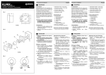
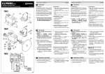
LFT25B Instrucciones de instalación 009 FOTOCÉLULA/ PHOTOCELLULE PHOTOCELL/ FOTOCÉLULA/ LICHTSCHRANKE 1 MSL-005/01 Español 1 DESCRIPCIÓN Advertencias Las fotocélulas LFT25B009 están diseñadas para detectar obstáculos en instalaciones de puertas y portones automáticos, evitando que se produzca la colisión con la puerta. Se componen de un módulo emisor (TX) y un módulo receptor (RX) de rayos infrarrojos. Si una persona u objeto interrumpe con su presencia el rayo de luz emitido por el emisor (TX), el receptor (RX) detecta el obstáculo e informa al cuadro de maniobra de la instalación. Instale y emplee el aparato respetando las indicaciones de estas instrucciones. El empleo inadecuado puede ser causa de averías y situaciones peligrosas. • • • • • – el emisor (TX) puede funcionar con baterías (puede instalarlo en la hoja móvil sin necesidad de cables) – el emisor (TX) dispone de bornes para conectar la banda de seguridad (LM) (puede conectar la banda en el emisor (TX), evitando su cableado hasta el cuadro de maniobra) Alimentación del emisor seleccionable mediante J1: – 2 baterías (Ref: LFTBAT009), duración 15 meses – alimentación externa (12-24V ac/dc) Alimentación receptor: externa 12-24V ac/dc Consumo emisor/ receptor: <500μA/ 30mA Alcance haz infrarrojo: 25m nominales (8m en exterior) Dimensiones: ver fig.1 Características Contenido (fig. 2) • Salida libre de tensión mediante relé con contactos NC (normalmente cerrado) y NA (normalmente abierto) • Test point (TP), para comprobar la alineación del haz infrarrojo • Sencillez de cableado: • • • • 2 Módulo emisor: base (1a) y tapa (6a) Módulo receptor: base (1b) y tapa (6b) Dos plantillas de taladrado (8) 6 tornillos de fijación y ajuste (2), 2 tornillos de fijación de tapas (7), 6 arandelas de goma (3), 6 topes de espuma (4), 2 prensaestopas (5). ecológica. Realice la instalación siguiendo el reglamento de baja tensión y las normas aplicables. Consulte las instrucciones del cuadro de maniobra para realizar las conexiones. Montaje y conexionado 1 Elija una ubicación para los conjuntos emisor y receptor. Los dos módulos deben estar lo más alineados posible. La altura a la que deben instalarse las fotocélulas depende de cada instalación (consulte la normativa correspondiente). El emisor puede montarse en la hoja móvil de la puerta y funcionar con pilas. 2 Utilizando las plantillas (8) suministradas, realice los orificios apropiados, dependiendo de la superficie de fijación (metal: ø3mm; muro: ø5mm). 3 Introduzca el cableado y realice las conexiones como se muestra en la figura 3. O Banda de seguridad: si no conecta banda de seguridad (LM) en el emisor (TX), coloque un puente entre los bornes de conexión. O Alimentación con 12-24Vdc: respete la polaridad, en caso contrario el aparato no funcionaría. O Alimentación con 12-24Vac: la polaridad es indiferente. 4 Mediante J1, seleccione el modo de alimentación del módulo emisor. – Posición A: alimentación externa 12-24Vac/cc – Posición B: alimentación mediante baterías 5 Inserte tacos de expansión (si fueran necesarios) y fije los módulos con los tornillos (2) intercalando las arandelas (3) y topes (4). 6 Si va a utilizar baterías, colóquelas. Alineación del haz infrarrojo 1 Conecte la alimentación eléctrica y compruebe el funcionamiento de las fotocélulas. Cuando el receptor recibe correctamente el rayo enviado por el emisor, el contacto NC permanece cerrado y DL1 encendido. Al DESCRIPTION Les photocellules LFT25B009 sont conçues pour détecter les obstacles sur les installations de portes et de portails automatiques, afin d´éviter les collisions avec la porte. Elles sont composées d´un module émetteur (TX) et d´un module récepteur (RX) à rayons infrarouges. Si une personne ou un objet interrompt avec sa présence le rayon de lumière émis par l´émetteur (TX), le récepteur (RX) détecte l´obstacle et en informe l´armoire de commande de l´installation. Installez et utilisez l´appareil en respectant les indications de ces instructions. L´utilisation incorrecte peut provoquer des pannes et des situations dangereuses. • • • • Diagnóstico de averías En caso de que las fotocélulas no funcionen correctamente, compruebe lo siguiente: • la tensión de alimentación del emisor y receptor – J1 debe estar en la posición correcta (A: alimentación externa 12-24Vac/dc; B: baterías) – si utiliza tensión continua, compruebe la polaridad – si utiliza baterías, compruebe que no están descargadas • si ha conectado banda de seguridad en el emisor (TX), compruebe su estado y funcionamiento (consulte su manual de instrucciones) • si no ha conectado banda de seguridad en el emisor (TX), compruebe que existe un puente eléctrico en sus bornes de conexión • la alineación del haz infrarrojo, midiendo la tensión en los puntos TP • que las fotocélulas no han sufrido daños debido a la intemperie o a posibles golpes de agentes externos Module émetteur: base (1a) et écran (6a) Module récepteur: base (1b) et écran (6b) Deux patrons de perçage (8) 6 vis de fixation et réglage (2), 2 vis de fixation de couvercles (7), 6 rondelles en caoutchouc (3), 6 butées en mousse (4), 2 presse-étoupes (5). INSTALLATION Réalisez l´installation en suivant le règlement 4 Fije las tapas (6) del emisor y receptor mediante los tornillos (7). 5 Con las tapas (6) ya colocadas, vuelva a comprobar el correcto funcionamiento de las fotocélulas. • Contenu (fig. 2) 2 Mida con un voltímetro el valor de tensión existente en el test-point (TP) del módulo receptor. Valor aproximado con el rayo interrumpido o las fotocélulas desalineadas: -0,7 V Valor aproximado con el rayo sin interrumpir y las fotocélulas alineadas: 0,4 - 0,6 V 3 Actúe sobre los tornillos de ajuste (2) del emisor y receptor hasta alcanzar una medida de la tensión adecuada, que indique que el haz infrarrojo está correctamente alineado. Valor óptimo: entre 0,5 y 0,6 V. Cuanto mejor sea la alineación, mayor es la tensión. • • • • Sortie libre de tension par relais avec contacts NC (normalement fermé) et NA (normalement ouvert) • Test point (TP), pour vérifier l´alignement du rayon infrarouge • Câblage simple: – l´émetteur (TX) peut fonctionner avec des batteries (vous pouvez l´installer sur le vantail Éliminez l´emballage de façon sûre et (por ejemplo, la distancia entre las fotocélulas y su alineación). • mobile sans besoin de câbles) – l´émetteur (TX) dispose de bornes pour connecter la bande de sécurité (LM) (vous pouvez connecter la bande sur l´émetteur (TX), en évitant ainsi le câblage jusqu´à l´armoire de commande) Alimentation de l´émetteur sélectionnable avec J1: – 2 batteries (Réf: LFTBAT009), durée 15 mois – alimentation externe (12-24V ac/dc) Alimentation récepteur: externe 12-24V ac/dc Consommation émetteur/récepteur: <500μA/ 30mA Portée rayon infrarouge: 25m nominaux (8m à l´extérieur) Dimensions: voir illustration 1 Caractéristiques interrumpir el rayo, se abre el contacto NC y DL1 se apaga. Este valor depende de varios parámetros Français Avertissements 2 INSTALACIÓN Elimine el embalaje de forma segura y Instructions d´installation écologique. de basse tension et les normes applicables. Consultez les instructions de l´armoire de commande pour réaliser les connexions. Montage et connexions 1 Choisissez un emplacement pour les ensembles émetteur et récepteur. Les deux modules doivent être le plus alignés possible. La hauteur à laquelle doivent être installées les photocellules dépend de chaque installation (consultez la réglementation correspondante). L´émetteur peut être monté sur le vantail mobile de la porte et fonctionner avec des piles. 2 Utilisez les patrons (8) fournis pour réaliser les orifices appropriés, en fonction de la surface de fixation (métal: ø3mm; mur: ø5mm). 3 Introduisez le câblage et réalisez les connexions comme indique l´illustration 3. O Bande de sécurité: si vous ne connectez pas la bande de sécurité (LM) sur l´émetteur (TX), placez un pont entre les bornes de connexion. O Alimentation avec 12-24Vdc: respectez la polarité, sinon l´appareil ne fonctionnera pas. O Alimentation avec 12-24Vac: la polarité est indifférente. 4 Avec J1, sélectionnez le mode d´alimentation du module émetteur. – Position A: alimentation externe 12-24Vac/cc – Position B: alimentation avec batteries 5 Introduisez des butées d´expansion (si besoin), puis fixez les modules avec les vis (2) en intercalant les rondelles (3) et les butées (4). 6 Si vous allez utiliser des batteries, placez-les. Alignement du rayon infrarouge 1 Connectez l´alimentation électrique et vérifiez le fonctionnement des photocellules. Lorsque le récepteur reçoit correctement le rayon envoyé par l´émetteur, le contact NC reste fermé et DL1 allumé. Si le rayon est interrompu, le contact NC s´ouvre et DL1 s´éteint. 2 Mesurez la valeur de la tension existante avec un voltmètre dans le test-point (TP) du module récepteur. Valeur approximative avec le rayon interrompu ou les photocellules non alignées: -0,7 V Valeur approximative avec le rayon sans interruption et les photocellules alignées: 0,4 - 0,6 V Cette valeur dépend de plusieurs paramètres (par exemple, la distance entre les photocellules et leur alignement). 3 Agissez sur les vis de réglage (2) de l´émetteur et du récepteur jusqu´à atteindre une mesure adéquate de la tension, ce qui indique que le rayon infrarouge est correctement aligné. Valeur optimale: entre 0,5 et 0,6 V. Plus l´alignement est bon, plus la tension est grande. 4 Fixez les écrans (6) de l´émetteur et du récepteur avec des vis (7). 5 Une fois que les écrans (6) sont placés, vérifiez à nouveau le fonctionnement correct des photocellules. Diagnostic de pannes Si les photocellules ne fonctionnent pas correctement, vérifiez les éléments suivants: • la tension de l´alimentation de l´émetteur et du récepteur – J1 doit être sur la position correcte (A: alimentation externe 12-24Vac/dc; B: batteries) – si vous utilisez une tension continue, vérifiez la polarité – si vous utilisez des batteries, vérifiez qu´elles ne soient pas déchargées • si vous avez connecté une bande de sécurité sur l´émetteur (TX), vérifiez son état et son fonctionnement (consultez le mode d´emploi) • si vous n´avez pas connecté de bande de sécurité sur l´émetteur (TX), vérifiez qu´il existe un pont électrique sur les bornes de connexion • l´alignement du rayon infrarouge, en mesurant la tension sur les points TP • que les photocellules n´aient pas souffert de dommages causés par l´intempérie ou de possibles coups d´agents externes Installation instructions 1 English Instruções de instalação 1 DESCRIPTION Warnings LFT25B009 photocells are designed to detect obstacles in automatic door and gate installations, preventing collision with the door/gate. They are made up of an infrared emitter module (TX) and receiver module (RX). If the presence of a person or object interrupts the light beam emitted by the emitter (TX), the receiver (RX) detects the obstacle and informs the control panel of the installation. Install and use the device in line with these instructions. Inappropriate use may lead to failures and hazardous situations. – • • • • • the emitter (TX) has terminals to connect the safety strip (LM) (the strip can be connected in the emitter (TX), avoiding its cabling through to the control panel) Emitter power supply, selectable by way of J1: – 2 batteries (Ref: LFTBAT009), battery life 15 months – external power supply (12-24V ac/dc) Receiver power supply: external 12-24V ac/dc Emitter/receiver consumption: <500μA/ 30mA Infrared beam range: 25m nominal (8m outdoors) Dimensions: see fig.1 Português 1 DESCRIÇÃO Advertências As fotocélulas LFT25B009 estão projectadas para detectar obstáculos em instalações de portas e portões automáticos, evitando que ocorra a colisão com a porta. São formadas por um módulo emissor (TX) e um módulo receptor (RX) de raios infravermelhos. Se uma pessoa ou objecto interrompe, com a sua presença, o raio de luz emitido pelo emissor (TX), o receptor (RX) detecta o obstáculo e informa o quadro de manobra da instalação. Instale e use o aparelho respeitando as indicações destas instruções. O uso inadequado pode causar avarias e situações perigosas. – • • • • • o emissor (TX) possui bornes para conectar a banda de segurança (LM) (pode conectar a banda no emissor (TX), evitando a sua cablagem até o quadro de manobra) Alimentação do emissor seleccionável mediante J1: – 2 baterias (Ref: LFTBAT009), duração 15 meses – alimentação externa (12-24V ac/dc) Alimentação receptor: externa 12-24V ac/dc Consumo emissor/ receptor: <500μA/ 30mA Alcance feixe infravermelho: 25m nominais (8m no exterior) Dimensões: ver fig.1 Characteristics Content (fig. 2) Características Conteúdo (fig. 2) • • • • • • • • • • • • Voltage-free output by way of relay with NC (normally closed) and NA (normally open) contacts. Test point (TP) to check the alignment of the infrared beam Straightforward cabling: – the emitter (TX) can work with batteries (it can be installed in the moving leaf without the need for cables) 2 the packaging safely and in an environmentally friendly manner. regulations and applicable rules. Check the instructions for the control panel in order to make the connections. Assembly and connections 3 Choose a location for the emitter and receiver equipment. The two modules should be as aligned as possible. The height at which the photocells should be installed depends on each installation (check the corresponding legislation). The emitter can be mounted on the moving leaf of the door/gate and run off batteries. Using the supplied templates (8), make the appropriate orifices, depending on the attachment surface (metal: ø3mm; masonry: ø5mm). Introduce the cabling and make the connections as shown in figure 3. O Safety strip: if a safety strip (LM) has not been connected in the emitter (TX), place a bridge between the connection terminals. O Power supply with 12-24Vdc: respect the polarity, otherwise the device will not work. O Power supply with 12-24Vac: the polarity is 4 5 6 indifferent. Using J1, select the emitter module power supply mode. – Position A: external power supply 12-24Vac/dc – Position B: power supply by way of batteries Insert expansion plugs (where necessary) and secure the modules with the screws (2), interchanging the washers (3) and stoppers (4). If batteries are to be used, put them in position. Infrared beam alignment 1 • Connect the electrical power supply and check the operation of the photocells. When the receiver correctly receives the beam sent by the emitter, the NC contact remains closed and DL1 on. When the beam is interrupted, the NC contact opens and DL1 goes off. Saída livre de tensão mediante relé com contactos NC (normalmente fechado) e NA (normalmente aberto) Test point (TP), para verificar o alinhamento do feixe infravermelho Simplicidade da cablagem: – o emissor (TX) pode funcionar com baterias (pode ser instalado na folha móvel sem necessidade de cabos) 2 2 Complete the installation in line with low voltage 2 • INSTALLATION Discard 1 Emitter module: base (1a) and cover (6a) Receiver module: base (1b) and cover (6b) Two bore templates (8) 6 attachment and adjustment screws (2), 2 cover attachment screws (7), 6 rubber washers (3), 6 foam stoppers (4), 2 glands (5). 3 4 5 Use a voltmeter to check the voltage at the test point (TP) of the receiver module. Approximate value with the beam interrupted or the photocells misaligned: -0.7 V Approximate value with the beam not interrupted and the photocells aligned: 0.4 - 0.6 V This value depends on several parameters (such as the distance between the photocells and their alignment). Turn the adjustment screws (2) of the emitter and receiver until suitable tension is achieved, indicating that the infrared beam is correctly aligned. Optimum value: between 0.5 and 0.6 V. The better the alignment, the greater the voltage. Secure the covers (6) of the emitter and receiver using the screws (7). With the covers (6) in place, once again check the correct operation of the photocells. Failure diagnosis Should the photocells not work correctly, check the following: • the power supply voltage of the emitter and receiver – J1 should be in the correct position (A: external power supply 12-24Vac/dc; B: batteries) – if direct current is used, check the polarity – if batteries are used, check that they are not flat • if a safety strip has been connected in the emitter (TX), check its state and operation (see the instructions manual) • if a safety strip has not been connected in the emitter (TX), check that there is an electrical bridge in the connection terminals • the alignment of the infrared beam, measuring the voltage at the TP points • that the photocells have not suffered any damage from the weather or from possible banging from external agents a embalagem de forma segura e ecológica. tensão e as normas aplicáveis. Consulte as instruções do quadro de manobra para fazer as ligações. Montagem e ligações 3 Escolha uma localização para os conjuntos emissor e receptor. Os dois módulos devem estar o mais alinhados possível. A altura em que as fotocélulas devem ser instaladas depende de cada instalação (consulte a normativa correspondente). O emissor pode ser montado na folha móvel da porta e funcionar com pilhas. Com os moldes (8) fornecidos, faça os orifícios apropriados, dependendo da superfície de fixação (metal: ø3mm; muro: ø5mm). Introduza a cablagem e faça as ligações como mostrado na figura 3. O Banda de segurança: se não conectar banda de segurança (LM) no emissor (TX), coloque uma ponte entre os bornes de ligação. O Alimentação com 12-24Vdc: respeite a polaridade, caso contrário o aparelho não funcionará. O Alimentação com 12-24Vac: a polaridade é 4 5 6 indiferente. Mediante J1, seleccione o modo de alimentação do módulo emissor. – Posição A: alimentação externa 12-24Vac/cc – Posição B: alimentação com baterias Insira as buchas de expansão (se forem necessárias) e prenda os módulos com os parafusos (2) intercalando as anilhas (3) e os tampões (4). Se for usar baterias, coloque-as. Alinhamento do feixe infravermelho 1 Ligue a alimentação eléctrica e verifique o funcionamento das fotocélulas. Quando o receptor recebe correctamente o raio enviado pelo emissor, o contacto NC permanece fechado e DL1 aceso. Quando o raio é interrompido, abre-se o contacto NC e DL1 apaga-se. 3 4 5 Medir com um voltímetro o valor de tensão existente no test-point (TP) do módulo receptor. Valor aproximado com o raio interrompido ou as fotocélulas desalinhadas: -0,7 V Valor aproximado com o raio sem interromper e as fotocélulas alinhadas: 0,4 - 0,6 V Este valor depende de vários parâmetros (por exemplo, a distância entre as fotocélulas e seu alinhamento). Regule os parafusos de ajuste (2) do emissor e do receptor até conseguir uma medida de tensão adequada, que indique que o feixe infravermelho está correctamente alinhado. Valor óptimo: entre 0,5 e 0,6 V. Quanto melhor o alinhamento, maior será a tensão. Fixe as tampas (6) do emissor e do receptor com os parafusos (7). Com as tampas (6) já colocados, verifique novamente o correcto funcionamento das fotocélulas. Diagnóstico de avarias Se as fotocélulas não funcionam correctamente, verifique o seguinte: • a tensão de alimentação do emissor e do receptor. – J1 deve estar na posição correcta (A: alimentação externa 12-24Vac/dc; B: baterias) - se usa tensão contínua, verifique a polaridade – si usa baterias, verifique se não estão descarregadas • se tiver conectado uma banda de segurança no emissor (TX), verifique seu estado e funcionamento (consulte o seu manual de instruções) • se não tiver conectado uma banda de segurança no emissor (TX), verifique se existe uma ponte eléctrica nos seus bornes de ligação • o alinhamento do feixe infravermelho, medindo a tensão nos pontos TP. • se as fotocélulas não sofreram danos devido à intempérie ou a possíveis golpes de agentes externos – • • • • • der Sender (TX) verfügt über Anschlussklemmen für die Montage von Sicherheitskanten (LM) (die Kante kann direkt an den Empfänger (TX) angebracht werden und so kann eine Verkabelung bis zu Steuerung vermieden werden) Wählen Sie die Stromversorgung des Senders mittels J1. – 2 Batterien (Ref: LFTBAT009), Lebensdauer 15 Monate – externe Stromersorgung (12-24V ac/dc) Stromversorgung des Empfängers: extern 12-24V ac/dc Verbrauch Sender/ Empfänger: <500μA/ 30mA Reichweite des Infrarotstrahls: 25m (8m im Aussenbereich) Maße: Siehe Abb.1 Eigenschaften Inhalt (Abb. 2) • • • • • Sendemodul: Untersatz (1a) und Abdeckung (6a) Empfangsmodul: Untersatz (1b) und Abdeckung (6b) Zwei Bohrvorlagen (8) 6 Schrauben für Befestigung und Einstellung (2), 2 Schrauben zur Befestigung der Abdeckung (7), 6 Gummi- Schraubenmuttern (3), 6 Puffer (4), 2 Stopfbuchsen (5). 2 Messen Sie mit Hilfe des Voltmeters den Spannungswert am test- point (TP) des Empfangsmoduls. Ungefährer Wert beim unterbrochenen Strahl oder nicht richtig angebrachten Lichtschranken: 0,7 V Ungefährer Wert beim nicht unterbrochenen Strahl und richtig angebrachten Lichtschranken: 0,4 - 0,6 V Dieser Wert hängt von verschiedenen Parametern (zum Beispiel, von der Entfernung zwischen den Lichtschranken und deren Ausrichtung) ab. Mit Hilfe der Einstellschrauben (2) Sender und Empfänger so lange einstellen, bis der Spannungswert anzeigt, dass der Infrarotstrahl korrekt ausgerichtet ist. Optimaler Wert: zwischen 0,5 und 0,6 V. Je besser die Ausrichtung, desto höher der Spannungswert. Die Abdeckung (6) des Senders und des Empfängers den passenden Schrauben (7) befestigen. Überprüfen Sie die richtige Funktionsweise der Lichtschranken, nachdem die Abdeckungen (6) angebracht wurden. • Spannungsfreier Relaisausgang mit NC Schaltkontakten (normalerweise geschlossen) und NO Kontakten (normalerweise offen). Test point (TP), um die Ausrichtung des Infrarotstrahls zu überprüfen. Einfache Verkabelung: – der Sender (TX) kann mit Batterien betrieben wer den (kann ohne Kabel direkt an den beweglichen Flügel montiert werden) 2 2 BESCHREIBUNG Die LFT25B009 Lichtschranken wurden entwickelt, um bei automatischen Türen und Toren Hindernisse zu erkennen und so Zusammenstösse zu vermeiden. Sie bestehen aus einem Sendemodul (TX) und einem Infrarot- Empfangsmodul (RX). Unterbricht das Vorhandensein einer Person oder eines Gegenstandes den durch den Sender (TX) ausgestrahlten Lichtstrahl, erkennt der Empfänger (RX) ein Hindernis und meldet dies an die Steuerung der Anlage. Montieren und benutzen Sie das Gerät entsprechend dieser Installationsanweisung. Der unzweckmäßige Gebrauch kann zu Störungen und Gefahrsituationen führen. • Faça a instalação seguindo o regulamento de baixa 2 Módulo emissor: base (1a) e tampa (6a) Módulo receptor: base (1b) e tampa (6b) Dois moldes para fazer orifícios (8) 6 parafusos de fixação e ajuste (2), 2 parafusos de fixação das tampas (7), 6 anilhas de borracha (3), 6 tampões de espuma (4), 2 bucins (5). Deutsch Warnhinweise INSTALAÇÃO Elimine 1 Installationsanweisungen MONTAGE Entsorgen Sie das Verpackungsmaterial auf eine umweltfreundliche und sichere Art und Weise. Führen Sie die elektrische Installation unter Einhaltung der geltenden örtlichen Bestimmungen durch. Um die Verbindungen durchzuführen beachten Sie bitte Steuerung. die Gebrauchsanweisung der Montage und Anschluss 1 2 3 Wählen Sie eine Stelle für die Anbringung von Sender und Empfänger. Die beiden Module sollten möglichst auf einer Linie angebracht werden. Die Höhe, an der die Lichtschranke angebracht werden sollte hängt von der jeweiligen Anlage ab (beachten Sie die entsprechende Richtlinie). Der Empfänger kann auf dem beweglichen Torflügel angebracht und mit Batterien betrieben werden. Mit Hilfe der mitgelieferten Schablonen (8) bohren Sie für den Untergrund geeignete Öffnungen (Metal: ø3mm; Mauer: ø5mm). Führen Sie die Kabel ein und führen Sie die elektrischen Anschlüssen laut Abbildung 3 durch. O Sicherheitsleiste: falls Sie keine Sicherheitsleiste (LM) an den Empfänger (TX) anschliessen, machen Sie eine Überbrückung zwischen den Anschlussklemmen. O Stromversorgung 12-24Vdc: beachten Sie die Polarität, da das Gerät sonst nicht funktionireren kann. O Stromversorgung 12-24Vac: die Polarität spielt 4 5 6 keine Rolle. Mit J1, wählen Sie die Versorgungsart des Sendemoduls. – Lage A: externe Versorgung 12-24Vac/cc – Lage B: Versorgung mit Batterien Falls notwendig, Spreizdübel einführen und die Module mit Hilfe von Schrauben (2), Scheiben (3) und Puffern (4) anbringen. Falls Sie Batterien benutzen, setzen Sie diese ein, Ausrichtung des Infrarotstrahls 1 Schließen Sie den Strom an und überprüfen Sie das Funktionieren der Lichtschranken. Empfängt der Empfänger den vom Sender ausgesendeten Strahl auf korrekte Art und Weise, bleibt der NC- Kontakt geschlossen und DL1 bleibt an. Wird der Strahl unterbrochen, öffnet sich der NCKontakt und DL1 geht aus. 3 4 5 Störungssuche Falls die Lichtschranken nicht richtig funktionieren, überprüfen Sie Folgendes: • die Versorgungsspannung des Senders und des Empfängers – J1 muss sich in richtiger Lage befinden (A: externe Versorgung 12-24Vac/dc; B: Batterien) – falls Sie Gleichspannung benutzen, überprüfen Sie die Polarität – falls Sie Batterien benutzen, überprüfen Sie, ob diese nicht leer sind • Falls Sie eine Sicherheitsleiste am Empfänger (TX) montiert haben, überprüfen Sie deren Zustand und Funktionsweise (gemäß entsprechender Gebrauchsanweisung) • Falls Sie keine Sicherheitsleiste an den Empfänger (TX) angeschlossen haben, überprüfen Sie die Überbrückung zwischen den Anschlussklemmen • die Ausrichtung des Infrarotstrahls, indem Sie die Spannung in den TP- Punkten messen • ob die Photozellen keinen Schaden aufgrund von Witterung oder anderen äußeren Einflüssen genommen haben