1
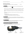
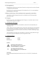
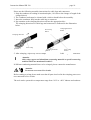
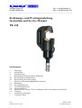
Auf dem Knapp 46 Tel.: ++49 (0)2191/907-0 D-42855 Remscheid Fax: ++49 (0)2191/907-141 _____________________________________________________________________________ Bedienungs- und Wartungsanleitung Instruction and Service Manual PK 120 Inhaltsangabe 1. 2. 3. 4. 4.1. 4.2. 5. 5.1. 5.2. 5.3. 5.4. 5.5 5.6. 6. 7. Einleitung Aufschriften Gewährleistung Beschreibung des hydraulischen Preßkopfes Beschreibung der Komponenten Beschreibung des Preßvorganges Hinweise zum bestimmungsgemäßen Gebrauch Bedienung Anwendungsbereich Verarbeitungshinweise Wartungshinweise Hinweis welche (Ersatz-) Teile vom Kunden selber ausgetauscht werden dürfen. Transport Verhalten bei Störungen Technische Daten JCS HE.8215_B V1b 9/99 HE8215_B.doc Anzahl der Seiten: 1 Bedienungsanleitung PK 120 Seite 2 ___________________________________________________________________________ Bedienungsanleitung für das hydraulische Preßwerkzeug Typ PK 120, Seriennummer ................WC1ff.. 1. Einleitung • Vor Inbetriebnahme Ihres Preßwerkzeuges lesen Sie sich die Bedienungsanleitung sorgfältig durch. • Benutzen Sie dieses Werkzeug ausschließlich für den bestimmungsgemäßen Gebrauch. • Einbau und Montage von Verbindungsmaterial mit Hilfe dieses Werkzeuges darf nur durch eine elektrotechnisch unterwiesene Person erfolgen. Das Mindestalter beträgt 16 Jahre. • Diese Bedienungsanleitung ist während der gesamten Lebensdauer des Werkzeuges mitzuführen. • Der Betreiber muß - dem Bediener die Betriebsanleitung zugänglich machen und - sich vergewissern, daß der Bediener sie gelesen und verstanden hat. 2. Aufschriften An dem Preßkopf finden Sie jeweils einen Aufkleber mit Firmenlogo/Firmennamen, Typenangabe und dem zulässigen Betriebsüberdruck. Die Serialnummer befindet sich auf dem Hydraulikzylinder. 3. Gewährleistung Die Gewährleistung beträgt bei sachgemäßer Bedienung und unter Einhaltung der geforderten regelmäßigen Kontrollen 1 Jahr ab Lieferdatum. 4. Beschreibung des hydraulischen Preßwerkzeuges 4.1. Beschreibung der Komponenten Das hydraulische Preßwerkzeug bestehen aus folgenden Komponenten: Bild 1 Werkzeugeinsätze Pos.-Nr. 1 Preßkopf Pos.-Nr. 2 Schnellkupplung Pos.-Nr. 3 Bedienungsanleitung PK 120 Seite 3 ___________________________________________________________________________ 4.2. Beschreibung des Preßvorganges Beim Preßvorgang werden die Werkzeugeinsätze gegeneinander gefahren. Der auf das Kabel aufgeschobene Kabelschuh/Verbinder befindet sich in der feststehenden Hälfte des Werkzeugeinsatzes. Der auf der Kolbenstange sitzende bewegliche Teil bewegt sich dabei auf die Preßstelle zu. Eine Pressung ist abgeschlossen, wenn die Werkzeugeinsätze (Pos.-Nr. 1) zusammengefahren sind und der zulässige Betriebsüberdruck erreicht wurde. Bei Erreichen des zul. Betriebsüberdrucks öffnet sich das Überdruckventil und leitet das Druckmedium (Hydrauliköl) wieder in den Vorratbehälter um. Die Angabe der Höhe des zul. Betriebsüberdruckes befindet sich auf dem Preßkopf. Weitere Hinweise zur Verpressung von Verbindungsmaterialien entnehmen Sie bitte unserem Montagehinweisen im Katalog. 5. Hinweise zum bestimmungsgemäßen Gebrauch In Verbindung mit einem 2 m Hochdruckschlauch (Pos.-Nr. 5) ist das Arbeiten im Kabelgraben nicht möglich. Für diese Anwendung wird mindestens ein 3 m Schlauch benötigt. 5.1. Bedienung des Gerätes 1. Anschluß des Preßkopfes (Pos.-Nr. 2) an die Fuß-/Elektropumpe und vollständiges Ausrollen des Hochdruckschlauches. 2. Einsetzen geeigneter Werkzeugeinsätze (Pos.-Nr. 1) und Positionierung des Preßkopfes (Pos.-Nr. 2). 3. Durchführung des Preßvorganges wie in Kap. 4.2. beschrieben. 4. Nach Erreichen des max. Betriebsdruckes wird der Kolben wieder in die Ausgangsposition zurückgefahren und das Verbindungsmaterial aus dem Preßkopf (Pos.Nr. 2) entfernt. Bedienungsanleitung PK 120 Seite 4 ___________________________________________________________________________ 5.2. Erläuterung des Anwendungsbereiches Unser hydraulisches Preßkopf vom Typ PK 120 verfügt über eine große Anzahl verschiedener Werkzeugeinsätze (Pos.-Nr. 1) zum Verpressen von Cu- und Al-Verbindungsmaterial. Tabelle 2 Bild 2 Preßbereich Verbindungsmaterial _____________________________________________________________________________________________________________ a 16-300 mm² Rohrkabelschuhe und Verbinder „Normalausführung“ _________________________________________________________________________________________________________ b 16-240 mm² Preßkabelschuhe und Verbinder DIN 46235/DIN 46267 _____________________________________________________________________________________________________________ c 10-300 mm² Aluminium Kabelschuhe und Verbinder _________________________________________________________________________________________________________ d 25-185 mm² Preßverbinder für zugfeste Verbindungen von Aldrey-Seilen nach DIN 48201, Blatt 6 und Al-Leiter DIN 48201, Blatt 5, 120 - 185 mm² _________________________________________________________________________________________________________ e 25/4-120/20 mm² Preßverbinder DIN 48085 Teil 3 für AL-/St-Seile DIN 48204 _________________________________________________________________________________________________________ f 10-300 sm mm² Runddrückeinsätze für für Al- und Cu-Sektorleiter _____________________________________________________________________________________________________________ g 16-150 mm² Quetschkabelschuhe DIN 46234, Stiftkabelschuhe DIN 46230 _________________________________________________________________________________________________________ h 10-95 mm² Isolierte Quetschkabelschuhe _____________________________________________________________________________________________________________ i 16-150 mm² Rohrkabelschuhe für feindrähtige Leiter _____________________________________________________________________________________________________________ j 10-70 mm² C-Klemmen _____________________________________________________________________________________________________________ k 10-150 mm² isolierte Rohrkabelschuhe und Verbinder sowie isolierte Stiftkabelschuhe _____________________________________________________________________________________________________________ l 2x50-2x95 mm² Doppelpreßkabelschuhe _____________________________________________________________________________________________________________ m 10-95 mm² ovale Preßverbinder nach DIN 48217 und Preßendbunde _____________________________________________________________________________________________________________ n 25-185 I mm² Aderendhülsen Achtung Es dürfen nur die der bestimmungsgemäßen Anwendung entsprechenden Verbindungsmaterialien verarbeitet werden. Sollten andere Verbindungsmaterialien verpreßt werden müssen, ist eine Rücksprache mit dem Werk zwingend erforderlich. Achtung Desweiteren dürfen keine unter Spannung stehenden Teile verpreßt werden. Vor Arbeitsbeginn ist ein spannungsfreier Zustand der zu verpressenden Verbindung sicherzustellen. Bedienungsanleitung PK 120 Seite 5 ___________________________________________________________________________ Das Gerät kann in einem Temperaturbereich von -20°C bis +40°C sowohl im Innen- als auch im Aussenbereich eingesetzt werden. 5.3. Verarbeitungshinweise Bei weiteren über die in Tabelle 2&3 angeführten Anwendungsfälle hinaus ist zwingend Rücksprache mit dem Werk zu halten. Tabelle 3 Kennzeichnung der Werkzeugeinsätze (Pos.-Nr. 1) Kennzeichnung Zuordn. Preßeinsätze Tab. 2 außen Preßprofil a Normalausführung CU, QS QS b DIN 46235/46267 CU, QS, Kennzahl DIN 46235 c Aluminium AL, QS Kennzahl d Al-Preßverbinder Al, QS Kennzahl Aldrey e Preßverbinder Al, QS Kennzahl DIN 48085 T3 St, QS Kennzahl f Runddruckeinsatz RU; QS, sm; QS, sm g Quetsch-/Stift-KS CU, QS, QS DIN 46234/46230 DIN 46234 h isol. Quetsch-KS ISQ, QS QS i KS f. feindr. Leiter F, QS QS, F j C-Klemmen C, QS QS k isol. Rohr-KS IS, QS l Doppelpreß-KS QS QS m ovale Preß-VB QS QS n AEH DIN 46228 AE, QS - Oberfläche des Preßeinsatzes Preßbreite gelb chromatiert gelb chromatiert 10-14 10-14 blau verzinkt blau verzinkt 5-14 12-14 blau verzinkt brüniert gelb chromatiert 12-14 12 - gelb chromatiert - gelb chromatiert gelb chromatiert gelb chromatiert gelb chromatiert gelb chromatiert schwarz brüniert gelb chromatiert - Abküzungen: KS-Kabelschuhe, VB-Verbinder, AEH-Aderendhülsen, QS-Querschnitt Mit den in Tabelle 3 Abs. a aufgeführten Einsätzen dürfen ausschließlich handelsübliche Klauke Rohrkabelschuhe und Verbinder verarbeitet werden. Eine Verpressung von handelsüblichen Kabelschuhen und Verbindern anderer Hersteller ergibt keine ordnungsgemäße Verpressung. Gleiches gilt für das Verbindungsmaterial aus Tab. 3g, 3h, 3i, 3j und 3k. Trotz gleicher Kennzahl sind die Preßbreiten bei Cu- und Al-Preßkabelschuhen und Verbindern unterschiedlich. Zur Kennzeichnung sind die Einsätze neben der Aufschrift noch farblich unterschiedlich ausgeführt. I Achtung Es dürfen auch bei gleicher Kennzahl nur die für das Material vorgesehenen Werkzeugeinsätze verwendet werden. Bedienungsanleitung PK 120 Seite 6 ___________________________________________________________________________ 5.4. Wartungshinweise Das hydraulische Werkzeug ist nach jedem Gebrauch zu reinigen und ein trockener Zustand vor Einlagerung sicherzustellen. Das Werkzeug ist weitgehend wartungsfrei. Der Preßkopf (Pos.-Nr. 2) ist nach möglichen Beschädigungen zu untersuchen. 5.5 Hinweis welche (Ersatz-) Teile vom Kunden selber ausgetauscht werden dürfen. Innerhalb des Gewährleistungszeitraums darf vom Kunden nur die Werkzeugeinsätze gewechselt werden. 5.6. Transport Das Werkzeug sollte, um Beschädigungen beim Transport zu vermeiden, immer in einem Transportkoffer transportiert werden. 6. Verhalten bei Störungen Erreicht der Preßkopf nicht seine volle Preßkraft, so kann Luft in das Hydrauliksystem eingedrungen sein. Abhilfe: Halten Sie bitte den Preßkopf tiefer als die Pumpe und betätigen Sie den Pumphebel bis die Preßeinsätze ihre Endlage erreicht haben. Diesen Vorgang wiederholen Sie bitte 2-3 mal. Erreicht die Pumpe dann noch nicht den vollen Druck, so muß der Entlüftungsvorgang wiederholt werden. Tritt Hydrauliköl an der Pumpe oder am Preßkopf aus, muß das jeweilige Bauteil oder ggf. das gesamte Aggregat zur Reparatur ins Werk eingeschickt werden. 7. Technische Daten Preßkraft: Gewicht: Betriebsdruck: 130 kN 5,5 kg 700 bar Symbole Sicherheitstechnische Hinweise Bitte unbedingt beachten, um Personenund Umweltschäden zu vermeiden. I Anwendungstechnische Hinweise Bitte unbedingt beachten, um Schäden am Gerät zu vermeiden. Anmerkung Diese Bedienungsanleitung kann kostenlos unter der Art.-Nr. HE.8215_B nachbestellt werden. Instruction Manual for the hydraulic crimping tool Type PK 120, Serial-No. ................WC1ff.. Index 1. 2. 3. 4. 4.1. 4.2. 5. 5.1. 5.2. 5.3. 5.4. 5.5. 6. 7. Introduction Labels Warranty Description of the hydraulic crimping unit Description of the components Description of the crimping processes Remarks with respect to the determined use Operation of the unit Explanation of the application range Mounting instructions Service and Maintenance instructions Reference as to which (spare-) parts can be exchanged by the customer Troubleshooting Technical data 1. Introduction Before starting to use the tool please read the instruction manual carefully. Use this tool exclusively for its determined use. Mounting and assembly of connecting material with the help of this tool must only be performed by specially trained personnel. The minimum age is 16 years. This instruction manual must be carried along during the entire life span of that tool. The operator must - guaranty the availability of the instruction manual for the user and - make sure, that the user has read and understood the instruction manual. 2. Labels On the labels fixed on the unit you’ll find the type specification, name of the manufacturer and/or the company logo. The serial number is on the hydraulic cylinder of the tool. 3. Warranty If correct operation is guaranteed and regular service is provided our warranty is 1 year from the time of delivery. Instruction Manual PK 120 page 8 _____________________________________________________________________________ 4. Description of the hydraulic crimping unit 4.1. Description of the components The hydraulic crimping tool type PK 120 consists of the following components: Picture 1 Dies Pos.-No. 1 Crimping head Pos.-No. 2 Coupling Pos.-No. 3 4.2 Description of the crimping procedure A crimping process is characterised by the closing motion of the dies (Pos.-No. 1). The cable lug or connector will be positioned in the stationary half of the crimping die. The piston will push the moving part of the die towards the compression point. The crimping process is complete when the dies contact each other and the maximum operating pressure of the pump is reached. More information about the assembly of the connecting material can be taken from the assembly instructions in our catalogue. 5. Remarks with respect to the determined use The crimping head PK 120 is designed for the use of interchangeable dies. In combination with a 2 m high-pressure hose it is not possible to work in a cable trench. For this application at least a 3m high-pressure hose is needed. 5.1. Operation of the unit 1.) First connect the crimping head (Pos.-No. 2) via the coupling (Pos.-No. 3) to the high pressure hose and roll out the hose completely 2.) Then you have to select the right dies (Pos.-No 1) for the intended application. 3.) Insert the connector and position the crimping head as needed. 4.) Actuate the pump until the dies are completely closed. 5.) After the crimping process has been completed and the piston must be retracted to remove the connecting material from the crimping head. Instruction Manual PK 120 page 9 _____________________________________________________________________________ 5.2. Explanation of the application range Our hydraulic crimping tool type PK 120 has a large number of various dies (Pos.-No. 1) available to crimp copper and aluminium connecting material. Table 2 Picture 3 Crimping range Connectors ________________________________________________________________________ a 16-300 mm² Tubular cable lugs and connectors „Standard type“ _____________________________________________________________________ b 16-240 mm² Compression cable lugs and joints DIN 46235/DIN 46267 ________________________________________________________________________ c 10-240 mm² Aluminium cable lugs and connectors _____________________________________________________________________ d 25-185 mm² Compression joints for full-tension connections for Aldrey conductors acc. to DIN 48201, sheet 6 and Al-conductors acc. to DIN 48201, sheet 5, 120-185 mm² _____________________________________________________________________ e 25-4 to mm² Compression joints acc. to DIN 48085, part 3 for 120-20 AL/steel conductors acc. to DIN 48204. ________________________________________________________________________ f 10-300 sm mm² Pre-rounding dies for Al- and Cu-Sectorconductors ________________________________________________________________________ g 16-150 mm² Solderless Terminals DIN 46234, Pin terminals DIN 46230 _____________________________________________________________________ h 10-95 mm² Insulated solderless terminals ________________________________________________________________________ i 16-150 mm² Tubular cable lugs for fine-stranded conductors ________________________________________________________________________ j 10-70 mm² C-clamps ________________________________________________________________________ k 10-150 mm² Pre-insulated tubular cable lugs and connectors, insulated pin cable lugs ________________________________________________________________________ l 2x50 to mm² Double compression cable-lugs 2x95 ________________________________________________________________________ m 10-95 mm² oval shape compression joints acc. to DIN 48217 and compression dead ends ________________________________________________________________________ n 25-185 mm² Cable end-sleeves Instruction Manual PK 120 page 10 _____________________________________________________________________________ Please use the following assembly instructions for cable lugs and connectors: 1. Strip the conductor according to insertion depth (+10% due to the change of length of the crimped sleeve) 2. The Conductor ends must be cleaned with a cloth or brush before the assembly. 3. Insert the conductor fully into the cable lug or connector 4. Pay attention to the crimping directions and use the appropriate dies. The crimping directions for cable lugs and connectors is indicated in the illustration below. First crimp Side a Crimping direction Side b Crimping direction picture 3 First crimp Crimping direction Side a First crimp Side b 5. After crimping, wipe away excess compound forced out of Al-cable lugs and connectors. I Attention Only crimp copper and Aluminium connecting material or special connecting material which are mentioned in table 2. If different conducting materials have to be crimped, please contact the manufacturer. Attention Do not use on or near live circuits. Before starting to crimp please make sure that all parts involved in the crimping process are not connected to live circuits. The tool can be operated in a temperature range from -20°C to +40°C indoors and outdoors. Instruction Manual PK 120 page 11 _____________________________________________________________________________ 5.3. Mounting instructions If applications other than those mentioned in table 2&3 are intended to be performed with this tool it is necessary to contact the manufacturer. Table 3 Marking of the dies relation dies Tab. 2 a b c d e f g h i j k l m n marking outside marking surface of the crimping dies profile „Standard type“ CU, „QS“ „QS“ chrome plated, yellow DIN 46235/ CU, „QS“, code chrome plated, DIN 46267 DIN 46235 number yellow Aluminium AL, „QS“ code blue zinc number Compression joint Al, „QS“ code blue zinc Aldrey number Compression joint Al, „QS“ code blue zinc number DIN 48085 part 3 ST, „QS“ code black number Pre-rounding dies RU; QS, sm; chrome plated, QS, sm yellow Terminals CU, „QS“, QS chrome plated, DIN 46234/46230 DIN 46234 yellow Insulated terminals ISQ, QS QS chrome plated, yellow Tub. CL for fine-str. F, QS QS chrome plated, conductors yellow C-clamps C, QS chrome plated, yellow Pre-insulated tub. IS, QS QS chrome plated, CL and connectors yellow double compression DP, QS QS chrome plated, CL yellow Oval compression CU or AL, QS code chrome plated, joints number yellow AEH DIN 46228 AE, QS chrome plated, yellow crimping width [mm] 10-14 10-14 5-14 12-14 12-14 12 - Abbreviations: CL-tubular cable lugs, AEH-cable end-sleeves, QS-Cross-section With those dies mentioned in Table 3a only Klauke cable lugs and connectors „Standard type“ are supposed to be crimped. Crimping of commercial cable lugs and connectors of other suppliers will not result in a perfect crimp. The same is valid for conducting material table 3j. No guarantee can be given for crimping C-clamps of other suppliers. Instruction Manual PK 120 page 12 _____________________________________________________________________________ Despite the same code numbers the compression width for copper and aluminium cable lugs and connectors is different. Besides the marking of the dies the plating is different too. Attention Even if the code number is identical only those dies should be used which are suitable for the material. I 5.4. Service and maintenance instruction The hydraulic tool must be cleaned and dried after each use. The tool is maintenance free. After one year we recommend sending the tool in to the manufacturer for an inspection. 5.5. Reference as to which spare parts can be exchanged by the customer Within the determined use of the tool only the dies (Pos.-No. 1) are permitted to be changed by the customer. Do not attempt to repair the tool yourself, and do not remove any parts such as screws and other components. 6. Troubleshooting - The tool loses oil. => Return the tool to the manufacturer. Do not open the tool. 7. Technical Data Crimping force: Weight: Max. operation pressure: approx. 130 kN approx. 5,5 kg 700 bar Symbols Safety warnings Please do not disregard these instructions in order to avoid human injuries and environmental damages. I Operational warnings Please do not disregard them to avoid damaging the pump unit. Note Additional copies of this manual are available without charge. The part # is HE.8215_B. Service PK 120 Seite/page 13 _____________________________________________________________________________ SLOWENIEN: DEUTSCHLAND FRANKREICH: Klauke Remscheid Herr Radtke Auf dem Knapp 46 42855 Remscheid Tel.: ++49 (0)2191/907-222 Fax: ++49 (0)2191/907-242 e-mail: [email protected] KLAUKE FRANCE Mr. Cordel 16, Rue Saint-Louis Z.I. Actisud 57150 Creutzwald (France) Tel.: ++33-3-87298470 Fax: ++33-3-87298479 E-MAIL: [email protected] GROSSBRITTANIEN Norwich Instrument Services Mr. Norman Cockburn 32 Hellesdon Park Road Drayton High Road Norwich NR6 5DR (UK) Tel.: 0044-1603-416900 Fax: 0044-1603-416902 E-Mail: [email protected] ISRAEL: ITALIEN: Shay A.U., Ltd. Mr. Shay Ind. Zone Kiriat Arieh Embar Street 23/25 P.O. BOX 10049 49222 Petach Tikva (Israel) Tel.: ++972-3-9233601 Fax: ++972-3-9234601 E-MAIL: [email protected] David Brown Hydraulics Italien S.r.l. Mrs. Albani Via del Costruttore, 64 41058 Vignola (MO) (Italy) Tel.: ++39-059-7700411 Fax: ++39-059-7700425 E-MAIL: [email protected] NIEDERLANDE: H.K. Electric B.V. Mr. Kleijn De Ateegen 7 5321 JZ Hadel (Niederlande) Tel.: ++31-73-5997599 Fax: ++31-73-5997590 E-Mail: [email protected] ÖSTERREICH: KLAUKE Handelsgesellschaft mbH Mr. Hruschka Kaiser-Franz-Josef-Str. 9 1230 Wien (Österreich) Tel.: ++43-1-8893436 Fax: ++43-1-8893433 E-MAIL: [email protected] POLEN/ UKRAINE: PORTUGAL: RB Brexim S.A. Marynin 7a 05-825 Grodzisk Mazowiecki (Polen) Tel.: ++48-22-7920273 oder 75 Fax: ++48-22-7923055 E-MAIL: [email protected] Palissy Galvani Electricidade Lda. Mr. Fernando Carvalho Rua Serpa Pinto, 15-A/P 1200 Lisboa (Portugal) Tel.: ++351-21-3223400 Fax: ++351-21-3223410 SPANIEN/ ANDORRA: Isaria d. o.o. Mrs. Zorz Proizvdnja in trgovina Cece 2a 1420 Trovlje (Slowenien) Tel.: ++386-356-31800 Fax: ++386-356-3180 Gave Electro S.A. Mrs. Amalia Paratge Coll-Blanc, S/N Aptdo. 12 08430 La Roca del Valles, Barcelona (Spanien) Tel.: ++34-93-8422212 Fax: ++34-93-8422227 E-MAIL: [email protected] TSCHECHISCHE REPUBLIK/ SLOVAKEI: Jiri Nitsch M. Pujmanove 1220/31 14000 Praha 4 – Prankrac (Tschechische Republik) Tel.: ++42-2-61213220 Fax: ++42-2-61213218 VOLKSREPUBLIK CHINA: Excellence Eng. & Trade Co, (lokaler Partner) Mr. Paul Wu Rm 1207B, T.P Plaza 9/109, LiuHua Road 5100010 Guagzhou (P.R. China) Tel.: ++86-20-86671150 Fax: ++86-20-86671141 E-MAIL: [email protected] (lokaler Partner) Beijing Tianze Electric Power Equipment Co.Ltd. Mr. Yu Yong Room 805/806 Kaitai Intl’Apartment 3# yard 5#building Yanjingli Zhong Street Chaoyang District 100025 Beijing (P.R. China) Tel.: ++86-10-67706841 Fax: ++86-10-67718723 E-MAIL: [email protected] (Service Ansprechpartner) Shanghai PuHuiFeng Machinery Equipment Maintenance Co.Ltd. Mr. Zhang Yulian No.7, 234 Changning Road 200042 Shanghai (China ZIP) Tel.: ++86-21-62254404 Fax: ++86-21-62254404 KOREA: Taehyung Hydraulic Tool Mr. Kim 140-5, Gamjeun-Dong, Sasang-Gu Busan 17-060 (Korea) Tel.: ++82-51-3171507 Fax: ++82-51-3171507 E-Mail: [email protected] SCHWEDEN Miltronic AB Mr. Thomas Fred Kungshagsvägen 7 S-611 29 Nyköping (Schweden) Tel.: 0046-155-77700 Fax: 0046-155-77702 E-Mail: [email protected] NORWEGEN Miltronic AS Mr. Hans Petter Selbo Dolasletta 5, 4308 Transby N-3421 Lierskogen (Norwegen) Tel.: 0047-32226610 Fax: 0047-32226656 E-Mail: [email protected] Service PK 120 Seite/page 14 _____________________________________________________________________________ UNGARN Trend Elektro Mr. Istvan Imrik H-1117 Budapest Dombovari ut 5-7 (Ungarn) Tel.: 0036-1-464-3118 Fax: 0036-1-464-3119 E-Mail: [email protected] TÜRKEI Ünal Kardes Mr. Servet Diricanli Eski Londra Asfalti No. 6 34630 Desyol-SefaköyIstanbul (Türkei) Tel.: 0090-212-6249204 Fax: 0090-212-5924810 E-Mail: [email protected] Schweden Bulgarien RUSSLAND Aib Ben Gim Mr. Ashot A. Haideyan Hilkov per. d.2, str.5, 2nd floor 119034 Moscow (Russland) Tel.: 007-095-203-9180 Fax: 007-095-203-4428 E-Mail: [email protected] LIBANON Georges Khoury & Co Mr. Alec Kouladjian p.o. box 11-8251 Bauchrieh Beirut-Lebanon (Libanon) Tel.: 00961-1-873872 Fax: 00961-1-894642 E-Mail: [email protected] Geplante (planned) Service-Center in 2002: ... EG-Herstellererklärung (nach Art. 4 Abs. 2 der EG-Richtlinie 98/37/EG) Dokument-Nr./ Monat, Jahr: 001PK120/06.99 Hersteller: Firma Gustav Klauke GmbH Anschrift: Auf dem Knapp 46 D-42855 Remscheid Produktbezeichnung: hydraulischer Preßkopf Typ PK 120 Die Inbetriebnahme ist so lange untersagt, bis die Konformität des kompletten elektrohydraulischen Aggregates mit den Richtlinien 98/37/EG und 72/23/EWG festgestellt ist. Wir bestätigen die Konformität des oben genannten Produktes mit der Richtlinie 98/37/EG. Aussteller: siehe Hersteller Ort, Datum: Remscheid, den 05.03.2003 Rechtsverbindliche Unterschrift: ............................................................ Dipl.-Ing. Joh.-Christoph Schütz, CE-Beauftragter Die Erklärung beinhaltet keine Zusicherung von Eigenschaften. Die Sicherheitshinweise der mitgelieferten Produktdokumentation sind zu beachten.