1
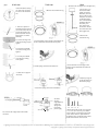
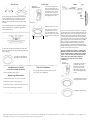
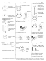
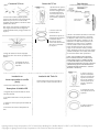
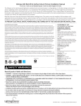
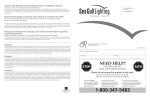
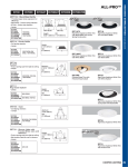
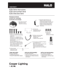
Glimpse LED Retrofit & Surface Mount Fixture Installation Manual
page 1
6 inch can, 5 inch can and J-box (Min Height: 2.25 in)
The Glimpse can be used in general lighting for residential and commercial spaces in ceiling lighting. It will reduce energy consumption
and cut operating costs by up to 80 percent. It is a maintenance-free operation that lasts up to 25 times longer than conventional
lighting. The Glimpse has a cool beam with no UV or IR that reduces air-conditioning loads. It has a unique design with painted white
housing for cooler operation and extended lamp life. The low profile fixture provides for the look and performance of conventional
recessed cans without the added material costs and labor.
Read the instruction sheet and all product labels before installing fixture. This product must be installed in full accordance with
applicable electrical and building codes by a person familiar with the construction and operation of this fixture and all involved hazards.
Installation should be performed by a qualified electrician in accordance with the National Electrical Code and relevant local codes.
TO PREVENT ELECTRICAL SHOCK, POWER SHOULD BE TURNED OFF AT THE FUSE BOX BEFORE INSTALLATION.
Limited Warranty/Limits of Liability
Lighting Science Group Corporation warrants our products to be free from defects in materials and workmanship under
normal use and service for a period of 5 years from date of purchase. This warranty extends to the original buyer or
end-user customer of a Lighting Science authorized reseller, and does not apply to fuses, batteries or to any product
which, in Lighting Science’s opinion, has been misused, altered, neglected or damaged by accident or abnormal conditions
of operation or handling. Lighting Science warrants that software will operate on appropriate Lighting Science product
substantially in accordance with its functional specifications for 90 days and that it has been properly recorded on nondefective media. Lighting Science does not warrant that software will be error free or operate without interruption.
Lighting Science’s warranty obligation is limited, at Lighting Science’s opinion, to refund of the purchase price, or free-ofcharge repair and/or replacement of defective product or component which is returned to an authorized Lighting Science
repair facility within the warranty period.
To obtain Lighting Science warranty service, contact your nearest Lighting Science service facility and provide a description
of the difficulty. Ship the product, postage and insurance prepaid (FCA destination), to your nearest Lighting Science service
facility. Lighting Science assumes no risk for damage in transit. Following warranty repair, product will be returned to buyer,
transportation prepaid (FCA destination). If Lighting Science determines that the failure was caused by misuse, alteration,
neglect or damage by accident or abnormal operation or handling conditions, Lighting Science will provide an estimate of
repair costs and obtain authorization prior to commencing repairs. Following repair, the product will be returned to buyer.
Transportation will be prepaid and the buyer will be billed for the repair and return transportation charges (FCA destination).
THIS WARRANTY IS PURCHASER’S SOLE AND EXCLUSIVE REMEDY AND IN IS IN LIEU OF ALL OTHER WARRANTIES,
EXPRESSED OR IMPLIED, INCLUDING, BUT NOT LIMITED TO, ANY IMPLIED WARRANTY OF MERCHANTABILITY OR
FITNESS FOR A PARTICULAR PURPOSE. LIGHTING SCIENCE SHALL NOT BE LIABLE FOR ANY SPECIAL, INDIRECT,
INCIDENTAL OR CONSEQUENTIAL DAMAGES OR LOSSES, INCLUDING LOSS OF DATA, LOST PROFITS OR LOST SAVINGS,
EVEN IF LIGHTING SCIENCE HAS BEEN ADVISED OF THE POSSIBILITY OF SUCH DAMAGES OR LOSSES, WHETHER
ARISING FROM BREACH OF WARRANTY OR BASED ON CONTRACT, TORT, RELIANCE OR ANY OTHER THEORY.
Since some countries and states do not allow limitation of the term of an implied warranty, or exclusion or limitation of
incidental or consequential damages, the limitations and exclusions of this warranty may not apply to every buyer. If any
provision of this warranty is held invalid or unenforceable by a court of competent jurisdiction, such holding will not affect
the validity or enforceability of any other provision of this warranty.
Copyright © Lighting Science Group Corporation 2011 All rights reserved. Lighting Science, Smart System, and Smart
Designer are trademarks of Lighting Science Group Corporation.
LISTA DE PRODUCTOS COMPATIBLES
SCREWBASE VERSION
VERSIÓN CON BASE ROSCADA
HALO
H7ICAT, H7RICAT, H7ICT, H7RICT, H7ICATNB,
H7ICTNB, H7T, H7RT, H7TNB, H7TCP, H7UICT,
H7UICAT, H27ICAT, H27RICAT, H27ICT,
H27RICT, H27T, H27RT, H5ICAT, H5RICAT, H5T,
H5RT, H25ICAT
ALL-PRO
EI500AT, EI500RAT, ET500, ET500R, EI700AT,
EI700RAT, EI700ATNB, EI700, EI700R, EI700NB,
ET700, ET700R, EI700U, EI700UAT, EI2700AT,
EI2700, EI2700R, ET2700, ET2700R
CAPRI CR1, PR1, QL1, R9ASIC
COMMERCIAL ELECTRIC
H2, H3, H4, H17, H18
ELCO EL71CA
JUNO
ICC22/R/W/S, IC23/W,IC21/R, TC2/R, IC20,
IC25/W/S, TC20
LIGHTOLIER
1104ICS/ICR/SIC/SICR, 1004ICS/ICR/SIC/SICR,
1104ICX
LITHONIA L7X, L7XP
PRESCOLITE IBXS
PROGRESS P87-AT, P86TG
SEAGULL 11018, 11028, 11118, 11128
THOMAS PS1, PS9RM
DISCONNECT VERSION
CAMERA-READY LOGOTYPE – UL CLASSIFICATION MARK FOR CANADA AND THE U.S.
These Marks are registered by Underwriters Laboratories Inc.
Certification
COMPATIBILITY LIST
VERSIÓN PARA DESCONEXIÓN
HALO H750ICAT, H750RICAT, H750T, H750TCP
Environment
SAFETY WARNINGS
Read all product labels and directions.
The minimum height of the registered trademark symbol ® shall be 3/64 of an inch. When the overall diameter of the
UL Mark is less than 3/8 of an inch, the trademark symbol may be omitted if it is not legible to the naked eye.
• Risk of fire or electric shock. LED Retrofit Kit installation requires knowledge of luminaires
electrical systems. If not qualified, do not attempt installation. Contact a qualified electrician.
• Risk of fire or electric shock. Install this kit only in the luminaires that have the construction
features and dimensions shown in the photographs and/or drawings.
• Installation should be performed only by a qualified electrician in accordance with the National Electrical Code and relevant local codes.
• Do not make or alter any open holes in an enclosure of wiring or electrical components during kit installation.
• INSTALLATION SHOULD ONLY BE PERFORMED AFTER POWER TO THE FIXTURE HAS BEEN DISCONNECTED.
• The recessed luminaire is intended for mounting only in a covered ceiling (where only the led side of the luminaire will be exposed to
damp or dry locations).
The font for all letter forms is Helvetica Condensed Black, except for the trademark symbol ®, which is
Helvetica Condensed Medium. No other fonts are acceptable.
Please Note:
The word "MARINE" should only be used for UL Classified marine products.
200-195I 20M/11/97
REF-00115
LSG_084_GlimpseInstallationManual Rev B
page 2
6 inch can
J-box
5 inch can
1. Reach inside the existing
can, and screw connector
into the socket inside the
can.
(Min Volume: 18 in3 , Min Length: 3.25 in, Min Height: 2.25 in)
1. On the j-box, you
will need to make 2
pigtail connections.
The black j-box wire,
which is the hot wire,
should be connected
to the black pigtail
wire of the enclosed
installation harness.
The white j-box
wire, which is the
neutral wire, should
be connected to the
white pigtail wire.
1. Remove the outside trim ring.
2. There are 3 options in
attaching the green ground
wire to the 6 inch can. The
ground wire needs to be
positioned under the nut.
Please select one of the
following:
2.a. Use the existing screw
inside the housing and just
tighten.
2. Remove the
outside trim ring.
2. Loosen bracket screws enough so the bracket can
can be rotated and removed from the keyhole.
2.b. Put the provided #8
nut on the existing screw.
Tighten.
2.c. Put the provided #8
screw into the existing
hole. Tighten.
3. Pull the springs off of the tab marked “6.”
3. Loosen bracket screws enough so the
bracket can be rotated and removed from
the keyhole.
3.a. Make sure to support
the fixture.
4. Pull the springs off
of the tab marked “6.”
Discard the springs.
4.a. Place the springs onto the tab marked “5.”
Slanted side
Power
Supply
Slanted side
3.b. Connect the orange male to the female
connector.
4.b. Make
sure the
angled(slanted)
side of the
springs faces
toward the
power supply.
1 ½”
8-32
¾”
¾”
8-32 6-32
¾” pointed
#6
5. Fasten the bracket to the j-box using the
1 ½” or ¾” 8-32. If necessary, use a drill to
screw in tighter. Note that the #6 pointed
screws can be used as a replacement for
the bracket screws to help dig into surfaces
harder than sheetrock such as wood.
Lighting Science Group Corporation l 1227 S. Patrick Drive Building 2A l Satellite Beach, FL 32937 l t. 877.999.5742 l www.lsgc.com
Copyright © Lighting Science Group Corporation 2011 All rights reserved.
6 inch can
5 inch can
For cans that require a housing adaptor please
follow manufacturer’s installation guide, then
proceed with step 5
6. Reattach the trim ring.
Once this adjustments is
completed, it is time to
start the installation into
the can. Refer to the 6 inch
can directions starting with
step 1.
5. After the springs are attached, push the disk
fixture up into the can, which is already attached
by the springs.
6. It is time to make the connections. The green
ground wire that is exposed and attached to the
fixture should be cut at the end that is the free
floaing ring terminal and the insulation stripped
½” back. The uninsulated j-box wires are ground
wires and will need to be connected to the green
ground wire. Wire nuts should be used to make
the connections. Next, make the connection
between male and female black connectors.
Finally make the connection between the male
and female orange connectors. Carefully push all
of the connections into the j-box.
(NOTE: IF POWER TO FIXTURE IS TURNED ON
BEFORE CONNECTION OF MALE AND FEMALE
BLACK CONNECTORS IS MADE THEN POWER
SUPPLY WILL GO INTO SELF PROTECT MODE
FOR 5 MINUTES. MAKE SURE POWER TO
FIXTURE IS OFF AND TRY AGAIN AFTER
5 MINUTES.)
6. Make sure the disk sits
flush against the surface.
• Start installation from Step 2.
page 3
5. Secure the springs into
place by reattaching the
bracket to the fixture. Place
the bracket screws in the
key holes and rotate the
bracket. Fasten the bracket
and tighten the screws.
4. The springs that are attached to the fixture
can be squeezed to be inserted into the can.
You can do this one by one, if that is easier.
Make sure to hook them on the inside of the
can tabs.
Installation into (Halo)
non-screw base recessed
J-box
Title 24 Installation
For Title 24 installation please proceed with
Step 2 of 6” Can installation.
7. Reattach the bracket
to fixture. Place the
bracket screws in the
key holes and rotate
the bracket. Fasten the
bracket and tighten the
screws.
Replacing LED Module
1. Make certain power to can is turned off.
8. Make sure the disk sits
flush against the surface.
2. Pull down on trim with finger tips.
3. Squeeze springs to remove module from can.
4. Disconnect LED orange connector.
9. Reattach the trim ring.
Lighting Science Group Corporation l 1227 S. Patrick Drive Building 2A l Satellite Beach, FL 32937 l t. 877.999.5742 l www.lsgc.com
Copyright © Lighting Science Group Corporation 2011 All rights reserved.
Manual de Instalación de Lámpara LED Glimpse de Montaje en Superficie y para Adaptaciones
page 4
Carcasa de 15,24 cm, carcasa y caja eléctrica de 12,7 cm (Altura Mínima de: 5,71 cm)
La Glimpse se puede utilizar para iluminación general de espacios residenciales o comerciales como iluminación de techo. Reducirá el consumo de energía
y abaratará los costos hasta en un 80 por ciento No requiere mantenimiento y dura hasta 25 veces más que las luces tradicionales. La Glimpse emite un haz
de luz fría, sin rayos UV ni IR por lo que reduce la carga de trabajo del aire acondicionado. Tiene un diseño único con una cubierta pintada de blanco para un
funcionamiento más fresco y una mayor vida útil de la lámpara.La lámpara de perfil discreto tiene la apariencia y el funcionamiento de las carcasas empotradas
convencionales sin los costos adicionales de los materiales y la mano de obra. Lee la hoja de instrucciones y todas las etiquetas del producto antes de instalar la
lámpara. Este producto debe ser instalado en absoluta conformidad con los códigos de construcción o de electricidad pertinentes por una persona familiarizada
con la construcción y operación de este producto y los riesgos implícitos. Un electricista calificado debe encargarse de la instalación según el Código Nacional
de Electricidad y los códigos locales pertinentes.
PARA EVITAR DESCARGAS ELÉCTRICAS, DEBES DESCONECTAR LA ELECTRICIDAD EN LA CAJA DE
FUSIBLES ANTES DE LA INSTALACIÓN.
Garantía Limitada/ Límites de responsabilidad
Lighting Science Group Corporation garantiza que nuestros productos no presentarán defectos materiales ni de
fabricación bajo condiciones normales de uso y mantenimiento, por el período de cinco años a partir la fecha de
compra. Esta garantía se extiende al comprador original o consumidor final de un distribuidor autorizado de Lighting
Science, y no se aplica a fusibles, baterías ni a ningún producto que, según la opinión de Lighting Science, ha sido mal
utilizado, modificado, descuidado o dañado por accidente o condiciones anormales de operación o manejo. Lighting
Science garantiza que el software operará en el producto apropiado de Lighting Science sustancialmente según sus
especificaciones funcionales por 90 días y que ha sido debidamente registrado en medios no defectuosos. Lighting
Science no garantiza que el software no tenga errores ni que funcione sin interrupciones.
La obligación de la garantía de Lighting Science está limitada, según la opinión de Lighting Science, a reembolsos del
precio de compra, o la reparación gratuita y/o reemplazo de un producto o componente defectuoso devuelto a alguna
instalación autorizada de reparación de Lighting Science dentro del período de la garantía.
Para obtener el servicio de garantía de Lighting Science, comuníquese con la instalación de servicio más cercana de Lighting
Science y describa el problema. Envíe el producto, franqueo y seguro pagado con anticipación (Franco Transportista
(Destino Acordado)) a la instalación de servicio de Lighting Science más cercana. Lighting Science no asume riesgos de
daños ocasionados durante el transporte. Luego de la reparación bajo la garantía, el producto se devolverá al comprador,
transporte pagado con anterioridad (Franco Transportista (Destino Acordado)). Si Lighting Science determina que la falla
fue causada por uso indebido, modificación, descuido o daño por accidente o condiciones anormales de funcionamiento
o manejo, Lighting Science proporcionará un estimado de costos de reparación y obtendrá una autorización previa a las
reparaciones. Luego de ser reparado, el producto se devolverá al comprador. El transporte será pagado con anticipación y
se facturará al comprador por la reparación y los costos del transporte (Franco Transportista (Destino acordado)).
ESTA GARANTÍA ES LA ÚNICA Y EXCLUSIVA SOLUCIÓN DEL COMPRADOR EN SUSTITUCIÓN DE CUALQUIER OTRA
GARANTÍA, EXPRESAS O IMPLÍCITAS, INCLUYENDO, ENTRE OTRAS, CUALQUIER GARANTÍA IMPLÍCITA DE COMERCIALIZACIÓN
O IDONEIDAD PARA UN PROPÓSITO EN PARTICULAR. LIGHTING SCIENCE NO SE HARÁ RESPONSABLE DE NINGUNA
PÉRDIDA O DAÑO ESPECIAL, INDIRECTO, INCIDENTAL NI CONSECUENTE, INCLUYENDO PÉRDIDA DE INFORMACIÓN,
PÉRDIDA DE GANANCIAS O AHORROS, AÚN SI SE HA NOTIFICADO A LIGHTING SCIENCE SOBRE LA POSIBILIDAD DE
TALES DAÑOS, PERJUICIOS O PÉRDIDAS; SI ELLO SE DERIVA DEL INCUMPLIMIENTO DE LA GARANTÍA O SE BASA EN
OBLIGACIONES CONTRACTUALES, EXTRACONTRACTUALES, CONFIANZA EN LAS MISMAS U CUALQUIER OTRA TEORÍA.
Debido a que algunos países y estados no permiten la limitación de los términos de una garantía implícita, o exclusión o
limitación de daños incidentales o consecuentes; las limitaciones y exclusiones de esta garantía no se aplican a todos los
compradores. Si un tribunal con jurisdicción competente declara alguna provisión de esta garantía inválida o inaplicable,
tal afirmación no afectará la validez o aplicabilidad del resto de las provisiones de esta garantía.
Copyright © Lighting Science Group Corporation 2011 Todos los derechos reservados. Lighting Science, Smart System y
Smart Designer son marcas registradas de Lighting Science Group Corporation.
CAMERA-READY LOGOTYPE – UL CLASSIFICATION MARK FOR CANADA AND THE U.S.
These Marks are registered by Underwriters Laboratories Inc.
Certificación
Ambiente
LISTA DE PRODUCTOS
COMPATIBLES
COMPATIBILITY LIST
VERSIÓN CON BASE ROSCADA
SCREWBASE VERSION
HALO
H7ICAT, H7RICAT, H7ICT, H7RICT,
H7ICATNB, H7ICTNB, H7T, H7RT, H7TNB,
H7TCP, H7UICT, H7UICAT, H27ICAT,
H27RICAT, H27ICT, H27RICT, H27T, H27RT,
H5ICAT, H5RICAT, H5T, H5RT, H25ICAT
ALL-PRO
EI500AT, EI500RAT, ET500, ET500R,
EI700AT, EI700RAT, EI700ATNB, EI700,
EI700R, EI700NB, ET700, ET700R, EI700U,
EI700UAT, EI2700AT, EI2700, EI2700R,
ET2700, ET2700R
CAPRI CR1, PR1, QL1, R9ASIC
COMMERCIAL ELECTRIC
H2, H3, H4, H17, H18
ELCO EL71CA
JUNO
ICC22/R/W/S, IC23/W,IC21/R, TC2/R,
IC20, IC25/W/S, TC20
LIGHTOLIER
1104ICS/ICR/SIC/SICR, 1004ICS/ICR/SIC/
SICR, 1104ICX
LITHONIA L7X, L7XP
PRESCOLITE IBXS
PROGRESS P87-AT, P86TG
SEAGULL 11018, 11028, 11118, 11128
THOMAS PS1, PS9RM
VERSIÓN PARA DESCONEXIÓN
DISCONNECT VERSION
HALO H750ICAT, H750RICAT, H750T,
H750TCP
ADVERTENCIAS DE SEGURIDAD
Lee todas las etiquetas e instrucciones del producto.
• Peligro de descarga eléctrica o incendio. La instalación del Kit de Adaptación de Luces LED requiere conocimientos
sobre sistemas eléctricos de lámparas. Si no estás calificado, no intentes la instalación. Contacta a un electricista calificado.
• Peligro de descarga eléctrica o incendio. Instala este kit sólo en las lámparas con las dimensiones y características estructurales
que se muestran en las fotografías y/o dibujos.
• La instalación debe hacerla solamente un electricista calificado según el Código Nacional de Electricidad y los códigos locales pertinentes.
• No abras ni modifiques agujeros abiertos en cajas de cableados o componentes eléctricos durante la instalación del kit.
• SÓLO SE DEBE HACER LA INSTALACIÓN DESPUÉS DE DESCONECTAR LA ELECTRICIDAD EN LA CAJA DE FUSIBLES.
• La luz empotrada debe montarse sólo en un techo cubierto (donde sólo el lado de la luz LED de la lámpara quede expuesto
a condiciones húmedas o secas).
The minimum height of the registered trademark symbol ® shall be 3/64 of an inch. When the overall diameter of the
UL Mark is less than 3/8 of an inch, the trademark symbol may be omitted if it is not legible to the naked eye.
The font for all letter forms is Helvetica Condensed Black, except for the trademark symbol ®, which is
Helvetica Condensed Medium. No other fonts are acceptable.
Please Note:
The word "MARINE" should only be used for UL Classified marine products.
200-195I 20M/11/97
REF-00115
LSG_084_GlimpseInstallationManual Rev B
Carcasa de 15,24 cm
Caja eléctrica
Carcasa de 12,7 cm
1. Dentro de la carcasa
existente, atornilla
el conector en el
portabombillas dentro de
la misma.
(Volumen Mínimo: 294 cm3 ,Longitud Mínima: 8,25 cm,
Altura Mínima: 5,71 cm)
1. En la caja eléctrica,
se deberán hacer 2
conexiones de extensión.
El cable negro de la caja
eléctrica, el cable vivo, se
debe conectar al cable
negro de extensión del
sujetador de instalación
incluido. El cable blanco
de la caja eléctrica, el
cable neutro, se debe
conectar al cable blanco
CONEXIÓN
DE EXTENSIÓN
de extensión.
1. Quita el borde decorativo
exterior.
TORNILLO DE SOPORTE
AFLOJADO
2. Hay 3 opciones para fijar
el cable verde a tierra a
una carcasa de 15,24 cm. Se
debe poner el cable verde
bajo la tuerca. Selecciona
una de las siguientes
opciones:
2.a. Utiliza el tornillo
dentro de la carcasa y
aprieta.
page 5
2. Quita el borde
decorativo exterior.
RANURA OJO
DE CERRADURA
2.Afloja los tornillos del soporte lo suficiente para
que el soporte de la carcasa se pueda rotar y quitar
de la ranura tipo ojo de cerradura.
TORNILLO DE
SOPORTE AFLOJADO
2.b. Coloca la tuerca núm.
8 en el tornillo existente.
Aprieta.
2.c. Coloca el tornillo núm.
8 en el orificio existente.
Aprieta.
RANURA OJO
DE CERRADURA
3. Afloja los tornillos del soporte lo
suficiente para que el soporte de la carcasa
se pueda rotar y quitar de la ranura tipo ojo
de cerradura.
3. Tira hacia afuera los resortes de la
pestaña marcada con un “6”.
4. Tira hacia afuera los
resortes de la pestaña
marcada con un “6”.
Deshecha los resortes.
3.a. Asegúrate de sostener
la lámpara.
CONECTOR MACHO DE LA
FUENTE DE ENERGÍA
CONECTOR HEMBRA DE LA
FUENTE DE ENERGÍA
4.a. Coloca los resortes en la pestaña marcada
con un “5”.
LADO SESGADO
Lado sesgado
FUENTE DE
ENERGÍA
3.b. Conecta el macho anaranjado al conector
hembra.
LADO SESGADO
4.b. Asegúrate
de que el lado
en ángulo
(sesgado) de
los resortes
quede hacia
la fuente de
energía.
1 ½”
8-32
¾”
¾”
8-32 6-32
¾” de punta
#6
5. Ajusta los soportes a la caja eléctrica con
el 8-32 de 1 ½” ó ¾”. Si es necesario, usa un
taladro para atornillar más fuerte. Nota que
los tornillos de punta núm. 6 se pueden
utilizar como reemplazo para los tornillos del
soporte para instalar en superficies más duras
que los tableros de yeso, como la madera.
Lighting Science Group Corporation • 1227 S. Patrick Drive Building 2A • Satellite Beach, FL 32937 • t. 877.999.5742 • www.lsgc.com
Copyright © Lighting Science Group Corporation • 2011 Todos los derechos reservados.
page 6
Carcasa de 15,24 cm
Carcasa de 12,7 cm
TORNILLO DE SOPORTE
AJUSTADO
4. Los resortes unidos a la lámpara pueden
oprimirse para insertarlos en la carcasa. Puedes
hacerlo uno por uno, si te es más sencillo.
Asegúrate de engancharlos en el interior de las
pestañas de la carcasa.
Para carcasas que requieran un adaptador, por
favor seguir las instrucciones de la guía de
instalación del fabricante y luego proceder con
el paso 5.
5. Fija de nuevo el soporte
en la lámpara y asegura los
resortes en el lugar. Coloca
los tornillos del soporte
en las ranuras tipo ojo de
cerradura y rota el soporte.
Fija el soporte y aprieta los
tornillos.
Caja eléctrica
(Volumen Mínimo: 294 cm3 ,Longitud Mínima: 8,25 cm,
Altura Mínima: 5,71 cm)
CONECTOR HEMBRA DE LA
FUENTE DE ENERGÍA
CONEXIÓN DE
EXTENSIÓN
CONECTOR MACHO DE LA
FUENTE DE ENERGÍA
RANURA OJO DE CERRADURA
6. Vuelve a colocar el
borde decorativo.
Terminados los ajustes, es
el momento de comenzar
la instalación dentro
de la carcasa. Lee las
instrucciones de la carcasa
de 15,24 cm comenzado
por el paso 1.
5. Luego de colocar los resortes, empuja la
lámpara tipo disco en la carcasa, ya fijada por los
resortes.
6. Ahora es el momento de hacer las conexiones.
El cable verde a tierra expuesto y conectado
a la lámpara se debe cortar en el extremo del
terminal circular flotante y pelarle 1,27 cm de
aislamiento. Los cables de la caja eléctrica sin
aislamiento son cables a tierra y se deberán
conectar al cable verde a tierra. Debes usar
tuercas de cables para hacer las conexiones.
Luego, une los conectores macho y hembra
negros. Finalmente, acopla los conectores macho
y hembra anaranjados. Con cuidado, mete todas
las conexiones dentro de la caja eléctrica.
(NOTA: SI SE ENCIENDE LA ELECTRICIDAD
DE LA LÁMPARA ANTES DE CONECTAR LOS
CONECTORES MACHO Y HEMBRA NEGROS,
LA FUENTE DE ENERGÍA SE ACTIVARÁ EN EL
MODO DE AUTOPROTECCIÓN POR 5 MINUTOS.
ASEGÚRATE DE QUE LA ELECTRICIDAD DE LA
LÁMPARA ESTÉ DESCONECTADA Y VUELVE A
TRATAR EN 5 MINUTOS).
6. Asegúrate de que el
disco quede a ras con la
superficie.
TORNILLO DE SOPORTE
AJUSTADO
Instalación en
bases empotradas sin tornillo
(Halo)
• Comienza la instalación por el Paso 2.
Reemplazar el Módulo LED
1. Asegúrate de que la electricidad a la carcasa
esté desconectada.
CONECTOR DEL
CUERPO DE
LA LÁMPARA
Instalación del Título 24.
Para la instalación del Título 24 procede por
favor con el Paso 2 de la carcasa de 15,24 cm.
7. Vuelve a colocar el
soporte en la lámpara.
Coloca los tornillos del
soporte en las ranuras
tipo ojo de cerradura y
rota el soporte. Fija el
soporte y aprieta los
tornillos.
RANURA OJO DE CERRADURA
8. Asegúrate de que el
disco quede a ras con la
superficie.
2. Tira del borde decorativo con la punta de los
dedos.
3. Oprime los resortes para quitar el módulo de
la carcasa.
4. Desconecta el conector anaranjado de la
LED.
9. Vuelve a colocar el
borde decorativo.
Lighting Science Group Corporation • 1227 S. Patrick Drive Building 2A • Satellite Beach, FL 32937 • t. 877.999.5742 • www.lsgc.com
Copyright © Lighting Science Group Corporation • 2011 Todos los derechos reservados.