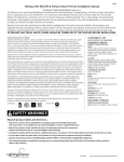
1
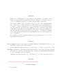
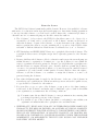
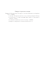
User’s Guide for FORTRAN Dynamic Optimisation Code DYNO M. Fikar and M. A. Latifi Rapport final Programme “Accueil de Chercheurs Étrangers” Conseil Régional de Loraine Fevrier 2002 Actual compilation:August 2, 2005 Abstract DYNO is a set of FORTRAN 77 subroutines for determination of optimal control trajectory with unknown parameters given the description of the process, the cost to be minimised, subject to equality and inequality constraints. The actual optimal control problem is solved via control vector parameterisation. That is, the original continuous control trajectory is approximated by a sequence of linear combinations of some basis functions. It is assumed that the basis functions are known and optimised are the coefficients of the linear combinations. In addition, each segment of the control sequence is defined on a time interval whose length itself may also be subject to optimisation. Finally, a set of time independent parameters may influence the process model and can also be optimised. It is assumed, that the optimised dynamic model is described by a set of ordinary differential equations. Contact M. A. Latifi Laboratoire des Sciences du Génie Chimique, CNRS-ENSIC, B.P. 451, 1 rue Grandville, 54001 Nancy Cedex, France. e-mail:[email protected], tel. +33 (0)3 83 17 52 34, fax +33 (0)3 83 17 53 26 M. Fikar Department of Information Engineering and Process Control, Faculty of Chemical and Food Technology, Slovak University of Technology in Bratislava, Radlinského 9, 812 37 Bratislava, Slovak Republic. email:[email protected], tel. +421 (0)2 593 25 354, fax +421 (0)2 39 64 69 Internet http://www.kirp.chtf.stuba.sk/∼ fikar/dyno.html Actual Version 1.2, 21.08.2004 From the licence The DYNO 1.x Software is not in the public domain. However, it is available for license without fee, for education and non-profit research purposes. Any entity desiring permission to incorporate this software or a work based on the software into commercial products or otherwise use it for commercial purposes should contact the authors. 1. The “Software”, below, refers to the DYNO 1.x (in either source-code, object-code or executable-code form), and a “work based on the Software” means a work based on either the Software, on part of the Software, or on any derivative work of the Software under copyright law: that is, a work containing all or a portion of the DYNO, either verbatim or with modifications. Each licensee is addressed as “you” or “Licensee”. 2. STU Bratislava and ENSIC-LSGC Nancy are copyright holders in the Software. The copyright holders reserve all rights except those expressly granted to the Licensee herein. 3. Licensee shall use the Software solely for education and non-profit research purposes within Licensee’s organization. Permission to copy the Software for use within Licensee’s organization is hereby granted to Licensee, provided that the copyright notice and this license accompany all such copies. Licensee shall not permit the Software, or source code generated using the Software, to be used by persons outside Licensee’s organization or for the benefit of third parties. Licensee shall not have the right to relicense or sell the Software or to transfer or assign the Software or source code generated using the Software. 4. Due acknowledgment must be made by the Licensee of the use of the Software in research reports or publications. Whenever such reports are released for public access, a copy should be forwarded to the authors. 5. If you modify a copy or copies of the Software or any portion of it, thus forming a work based on the Software, and make and/or distribute copies of such work within your organization, you must meet the following conditions: (a) You must cause the modified Software to carry prominent notices stating that you changed specified portions of the Software. (b) If you make a copy of the Software (modified or verbatim) for use within your organization it must include the copyright notice and this license. 6. NEITHER STU, ENSIC-LSGC NOR ANY OF THEIR EMPLOYEES MAKE ANY WARRANTY, EXPRESS OR IMPLIED, OR ASSUMES ANY LEGAL LIABILITY OR RESPONSIBILITY FOR THE ACCURACY, COMPLETENESS, OR USEFULNESS OF ANY INFORMATION, APPARATUS, PRODUCT, OR PROCESS DISCLOSED AND COVERED BY A LICENSE GRANTED UNDER THIS LICENSE AGREEMENT, OR REPRESENTS THAT ITS USE WOULD NOT INFRINGE PRIVATELY OWNED RIGHTS. 7. IN NO EVENT WILL STU, ENSIC-LSGC BE LIABLE FOR ANY DAMAGES, INCLUDING DIRECT, INCIDENTAL, SPECIAL, OR CONSEQUENTIAL DAMAGES RESULTING FROM EXERCISE OF THIS LICENSE AGREEMENT OR THE USE OF THE LICENSED SOFTWARE. Changes to previous versions Version 1.2 The main change was support for automatic differentiation and implementation of ADIFOR. • info(16): The input array info has one more element specifying the AD usage. • A new file has to be linked with DYNO: Either adifno.f if info(16)=0 or adifyes.f otherwise. • Documentation includes new section about usage of ADIFOR. • Examples are implemented both with and without AD tools. Contents 1 Introduction 1.1 Problem Formulation . . . . . . . . . . . . . . . . . . . . . . . . . . . . . . 1.1.1 System and Cost Description . . . . . . . . . . . . . . . . . . . . . 1.1.2 Optimised Variables . . . . . . . . . . . . . . . . . . . . . . . . . . 2 Optimal Control Problems 2.1 Control Parameterisation . . . . . . . 2.1.1 Piece-wise Continuous Control 2.2 State Path Constraints . . . . . . . . 2.2.1 Equality Constraints . . . . . 2.2.2 Inequality Constraints . . . . 2.3 Minimum Time Problems . . . . . . 2.4 Periodic Problems . . . . . . . . . . . 7 7 7 8 . . . . . . . . . . . . . . . . . . . . . . . . . . . . . . . . . . . . . . . . . . . . . . . . . . . . . . . . . . . . . . . . . . . . . . . . . . . . . . . . . . . . . . . . . . . . . . . . . . . . . . . . . . . . . . . . . . . . . . . . . . . . . . . . . . . . . . . . . . . . 9 9 10 10 11 11 14 15 3 Description of the Optimisation Method 3.1 Static Optimisation Problem . . . . . . . 3.2 Gradient Derivation . . . . . . . . . . . . 3.2.1 Procedure . . . . . . . . . . . . . 3.2.2 Notes . . . . . . . . . . . . . . . . . . . . . . . . . . . . . . . . . . . . . . . . . . . . . . . . . . . . . . . . . . . . . . . . . . . . . . . . . . . . . . . . . . . . . . . . . . . 16 16 16 18 19 4 Specification of the subroutines 4.1 Subroutine dyno . . . . . . . . . . . . . . . . . 4.2 Subroutine process . . . . . . . . . . . . . . . 4.3 Subroutine costi of Integral Constraints . . . 4.4 Subroutine costni of Non-integral Constraints 4.5 Organisation of Files and Subroutines . . . . . 4.5.1 Files . . . . . . . . . . . . . . . . . . . 4.5.2 Subroutines in dyno.f . . . . . . . . . 4.5.3 Reserved common blocks . . . . . . . . 4.5.4 Automatic Differentiation . . . . . . . . . . . . . . . . . . . . . . . . . . . . . . . . . . . . . . . . . . . . . . . . . . . . . . . . . . . . . . . . . . . . . . . . . . . . . . . . . . . . . . . . . . . . . . . . . . . . . . . . . . . . . . . . . . . . . . . . . . . . . . . . . . . . . . . . . . . . . . . . . . . . . . . 21 21 27 30 33 36 36 37 38 38 5 . . . . . . . 5 Examples 5.1 Terminal Constraint Problem . . . . . . . 5.2 Terminal Constraint Problem 2 . . . . . . 5.3 Inequality State Path Constraint Problem 5.4 Batch Reactor Optimisation . . . . . . . . 5.5 Non-linear CSTR . . . . . . . . . . . . . . 5.6 Parameter Estimation Problem . . . . . . References . . . . . . . . . . . . . . . . . . . . . . . . . . . . . . . . . . . . . . . . . . . . . . . . . . . . . . . . . . . . . . . . . . . . . . . . . . . . . . . . . . . . . . . . . . . . . . . . . . . . . . . . . . . . 42 42 43 44 46 48 49 51 6 Chapter 1 Introduction The speed of computers has enabled to solve many engineering problems that were not possible to deal with in the past. One of them is optimal control for dynamic systems. Many engineering problems fall into the scope of this formulation. Although the problem has received much attention in the literature, not many computer implementations currently exists. For this reason, we have developed the dynamic optimisation software package DYNO (DYNnamic Optimisation). The main aim of this report is to be a user manual. However, it also gives the theoretical foundations of the algorithms used so that the code and its usage is more comprehensible for the user. 1.1 Problem Formulation 1.1.1 System and Cost Description Consider an ordinary differential system (ODE) system described by the following equations ẋ = f (t, x, u, p), x(t0 ) = x0 (p) (1.1) where t denotes time from the interval [t0 , tP ], x∈ Rnx is the vector of differential variables, u∈ Rnu is the vector of controls, and p∈ Rnp is the vector of parameters. The vector valued function f ∈ Rnx describes the right hand sides of differential equations. We suppose that the initial conditions of the process can be a function of the parameters. We assume that the (originally continuous) control can be approximated as piece-wise constant on P time intervals u(t) = uj , tj−1 ≤ t < tj (1.2) and we denote the interval lengths by ∆tj = tj − tj−1 . 7 Consider now the criterion to be minimised J0 and constraints Ji of the form Z tP J0 = G0 (tj , x(t1 ), . . . , x(tP ), u(t1 ), . . . , u(tP ), p) + F0 (t, x, u, p)dt t0 Z tP Ji = Gi (tj , x(t1 ), . . . , x(tP ), u(t1 ), . . . , u(tP ), p) + Fi (t, x, u, p)dt (1.3) (1.4) t0 where the constraints are for i = 1, . . . , m, (m is the number of constraints). In the sequel we will assume that the constraints are ordered such that the first me are equality constraints of the form Ji = 0 and the last mi = m − me constraints are inequalities of the form Ji ≥ 0. The further constraints that are considered include simple bounds of the form max uj ∈ [umin ] j , uj min max ∆tj ∈ [∆tj , ∆tj ] p ∈ [pmin , pmax ] 1.1.2 (1.5) Optimised Variables The optimised variables y are parameters p, piece-wise constant parametrisation of control uj , and time interval lengths ∆tj . The reason for utilising ∆tj instead of tj is simpler description of the bounds (lower bound is usually a small positive number for ∆tj ). Also, simple bounds are more easily handled by NLP solvers. Hence the vector y∈ Rq of optimised variables is given as y T = (∆t1 , . . . , ∆tP , uT1 , . . . , uTP , pT ). (1.6) Example 1 (Minimum time problem for a linear system). Consider a system described by a second order linear time invariant equation y ′′(t) + 2y ′(t) + y(t) = u(t), y ′ (0) = 0, y(0) = 0 (1.7) and the task is to minimise the final time tf to obtain a new stationary state characterised by y ′ (tf ) = 0, y(tf ) = 1, and subject to the constraints on control u ∈ [−0.5, 1.5]. Let us divide the total optimisation time tf for example into 3 intervals where the control can be assumed to be constant. We can define the optimisation problem with the unknown variables u1 , u2 , u3 , ∆t1 , ∆t2 , ∆t3 . Rewriting the system equation into two first order ODE’s and specifying the constraints gives x′1 x′2 J0 J1 J2 ui ∆ti = = = = = ∈ ≥ x2 , u − x1 − 2x2 , ∆t1 + ∆t2 + ∆t3 x1 (t3 ) − 1 x2 (t3 ) [−0.5, 1.5], i = 1, 2, 3 0, i = 1, 2, 3 x1 (0) = 0 x2 (0) = 0 (1.8) 8 Chapter 2 Optimal Control Problems We discuss here some types of problems that can be solved by the package. 2.1 Control Parameterisation It might seem that the piece-wise constant control parameterisation can be too imprecise in certain situation and that it cannot approximate closely enough the original continuous type trajectory. Of course, one can take the number of time intervals P sufficiently large to obtain finer resolution. However, this will add to complexity of the master NLP problem, possibly find many local minima or it will results in convergence problems. However, also any other parameterisation can be reformulated for the problem with piece-wise constant controls. Consider for example piece-wise linear control of the form u(t) = a + bt (2.1) It is clear, that the coefficients a, b can serve as new commands. Hence u1 , u2 in u(t) = u1 + u2 t (2.2) are new control variables. Another useful parameterisation is by the Lagrange polynomials. These are defined as N Y t − ti Pj (t) = t − ti i=0,j j (2.3) where N is the degree of the polynomial Pj (t) and the notation i = 0, j denotes i starting from zero and i 6= j. The times ti are usually specified as the roots of the Legendre polynomials (Villadsen and Michelsen, 1978; Cuthrell and Biegler, 1989). 9 The control parameterisation can then be expressed as u(t) = N X ūj ψj (t), j=1 N Y t − ti ψj (t) = t − ti i=1,j j (2.4) and the elements ūi serve as piece-wise constant control variables in the optimisation. The advantage of the Lagrange polynomials follows from the fact, that u(ti ) = ūi (2.5) and thus the coefficients ūj are physically meaningful quantities. This is useful as their bounds are the same as the bounds on the original control. 2.1.1 Piece-wise Continuous Control By default, control variables across the time intervals are considered as independent. There are however, situations, when it is desired that the overall control trajectory remains continuous. There are two possible solutions: 1. Add constraints on control across time boundaries of the form + u(t− i ) = u(ti ) (2.6) This adds P − 1 equality constraints (each of dimension of the control vector). As these constraints do not contain states, no adjoint system of equations has to be generated for them. However, NLP solver can have convergence problems due to a large number of equality constraints. 2. Add a new state variable for each element of the control vector. It will represent control. Thus, its initial value has to be optimised (control at time t0 ) and its derivative is equal to the control approximation derivative. Assuming for example linear control parameterisation of the form uj = aj + bj t, the differential equation of the new state is given as ẋu = bj , x(t0 ) = a1 (2.7) and xu replaces all occurrences of control u in the process and cost equations. The optimised parameters are then b1 , . . . , bP , a1 – the slopes and the initial value. 2.2 State Path Constraints State path constraints are usually of the form g(x, u, p, t) ≥ 0, g(x, u, p, t) = 0, t ∈ [t0 , tP ] t ∈ [t0 , tP ] (2.8) (2.9) 10 and are in general very difficult to be satisfied along the desired time range. There are several methods that can deal with these constraints by either removing them or transforming them to the form (1.3). To do so, it is important to use only such kinds of transformations, that do not introduce non-smooth (non-differentiable) behaviour. 2.2.1 Equality Constraints These constraints impose relations between state and control variables. The consequence is that some of the control variables, or rather their linear combinations cannot be regarded as optimised variables, and the number of degrees of freedom in optimisation decreases. The first possible method when dealing with equality constraints that depend directly on control variables is to try to find explicitly the dependence of control on states and replace the corresponding control in the state and cost equations. If the constraints do not depend directly on control variables or this dependence is difficult to specify explicitly, one can use a general method of converting the path constraint to integral constraint. To do so, a new state variable is defined as ẋg = g(x, u, p, t), xg (0) = 0 (2.10) and this differential equation is appended to other state equations. If the equality constraint holds, the derivative is zero all the time and one can define an integral constraint of the form Z tP Z tP g g 2 J = (ẋ ) dt = (g)2 dt = 0 (2.11) t0 t0 If the integral constraint is zero, then the equality constraint holds. Due to the convergence reasons of the NLP, the equality is often relaxed to Z tP g J = g 2 dt < ε, ε > 0 (2.12) t0 Note that this means that a small violation of the constraint is allowed. 2.2.2 Inequality Constraints Integral Approach An inequality constraint can be transformed into an end-point constraint by the use of the integral transformation technique described above: Z tP g J = h(g)dt = 0 (2.13) t0 where h measures the degree of violation of the inequality constraint during the entire trajectory. Several formulations for selection of a suitable h have been proposed: 11 Max The most simple approach is to use h = min(g, 0). As the gradient of this operator is discontinuous, it poses problems in the integration and is in general not recommended. Max2 An improvement over the previous solution is to avoid the discontinuity, for example as with h = [min(g, 0)]2. Smoothing The proposition given in Teo et al. (1991) lies in the discontinuity replacement by a smooth approximation. Therefore, in the region of |g| < δ, a quadratic smoothing is employed: g if g < −δ 2 (g − δ) (2.14) h= − if |g| ≤ δ 4δ 0 if g > δ The advantage over the Max2 method is elimination of squaring, therefore small deviations are penalised more heavily. A drawback (in practice not very important) is slightly smaller feasibility region. The disadvantage of these methods is that no distinction is made whether the path constraint is not active on the overall trajectory or it is exactly at the limit. In both cases the integral is zero. Moreover, if the path constraint is not violated, its gradient with respect to the optimised parameters is zero. This poses problems to NLP and reduces its convergence speed considerably as it oscillates between zero and nonzero gradients. Further, the gradients are zero at the optimum. Interior point constraints As the previous methods transformed the inequality constraints into a single integral measure, only a very little information is given to NLP problem. A possible solution is to discretise the constraint and require it to be satisfied only at some points – usually at the end of the segments at times tj . Thus, g(tj ) ≥ 0 (2.15) Although such a formulation is more easily solved by the NLP solver, it can result in pathological behaviour when the constraint is respected only at the prescribed points but violated in between. The situation gets worse if also the times tj are optimised. The usual solution found contains one very large time tk within which the constraint exceeds largely the possible tolerated violation. The situation is better if the times are not optimised and tolerable constraint violations can be obtained. This approach is used in Model Predictive Control. 12 Combination of End and Interior Point Methods A straightforward improvement consists in the combination of the integral end-point function with the set of interior point constraints at the end time segments. The advantage lies in the fact that the NLP solver gets more information even when the integral is zero. There is a possible drawback: when gradients are calculated by the method of adjoint variables, as it is done in DYNO, because each interior point constraint is state dependent. Thus, for each point constraint, another system of adjoint equations has to be formed and integrated backwards in time. This slows down computational time significantly. Slack Variables The slack variable method (Jacobson and Lele, 1969; Bryson and Ho, 1975; Feehery and Barton, 1998) is based on the techniques of optimal control and among other methods mentioned above it is one of the most rigorous. However, it has many drawbacks so it cannot be used as a general purpose method. The principle of the method is given by changing the original inequality to equality by means of a slack variable a(t): 1 g(x) − a2 = 0 2 (2.16) The slack variable is squared so that any value of a is admissible. The equation is then differentiated so many times until a explicit solution for u can be found. The control variable is then eliminated from the system equations. Therefore, the principle of the method is to make the control (one scalar element from the control vector) a new state variable for the corresponding constraint. Thus, the state constraint is appended as equality to the system, the control variable is solved as a state variable during the integration and the slack variable a(t) becomes the new optimised variable (and it has to be parametrised suitably). The original proposition in Jacobson and Lele (1969) dealt only with ODE (ordinary differential equations). Improvement and generalisation of this procedure for general DAE (differential algebraic systems) has been proposed by Feehery and Barton (1998). Although the method is appealing and gives very good results, its drawbacks are as follows: • Number of the state constraints cannot be larger than the dimension of the control vector. The other approaches can give a feasible solution when the number of active constraints is equal or smaller than the control dimension. A possible workaround has been proposed by Feehery and Barton (1998) where state event based approach is used. • As the method changes the category of u from the optimised variable to a state variable, this means that any possible bounds on u cannot longer be satisfied. Therefore, 13 a control constraint is traded versus a state constraint. As in the real world any control signal has bounds well defined, it remains only to hope that these will not be violated. • If more control variables are candidates for state variables, no suitable selection strategy exists. In practice, usually a combination of control variables (not only one of them) influences the state constraint; the method is not capable to find it. • It is implicitly given that the control variable can vary continuously in time. There are some optimisation problems where control has to be piece-wise constant – for example bang-bang type of control strategy where only time lengths can be varied. On the other hand, the primary advantages are as follows: • Only feasible solutions are generated by the integration (IVP – initial value problem) solver. This may particularly be important when the solutions that violate the path constraint would generate feasibility problems to IVP solver. • The constraints are respected within the integration precision of the IVP solver and need not be relaxed for improved convergence of the optimisation. 2.3 Minimum Time Problems Many dynamic optimisation tasks lead to the formulations that minimise the time. To express it in the form of general description (1.3), two possible approaches can be used. The most straightforward is to define the cost function as J0 = G0 = ∆t1 + ∆t2 + · · · + ∆tP = the corresponding gradients are therefore P X ∆tj (2.17) j=1 ∂J0 =1 ∂∆tj (2.18) Other possibility is to define a parameter pt = tP and to describe the system differential equations with normalised time τ = t/pt , τ ∈ [0, 1] (assuming t0 = 0 for simplicity). This yields dx = pt f (t, x, u, p) (2.19) dτ This normalisation also influences the general cost description that is now written as Z 1 Ji = Gi (τj , x(1/P ), . . . , x(1), u(1/P ), . . . , u(1), p, pt ) + Fi (t, x, u, p, pt )dt (2.20) 0 and the minimum time cost formulation is then simply J0 = G0 = pt (2.21) 14 2.4 Periodic Problems Sometimes, the dynamic optimisation problem is specified to find a periodic operational policy – that the process operates in quasi stationary state when the time-scale of the problem is enlarged. Consider for example bang-bang type of control, where the control variable can attain only low and high value. Of course, if stationary operation of the process is desired, such a control policy is undesirable. However, if stationarity is defined by constraining the process to be in some interval of states, bang-bang type of control is perfectly admissible. Mathematically speaking, the periodic operation problem can be stated as: Find such an operating policy and such an initial states vector x0 = p so that the constraint x(tP ) = p (2.22) is respected. Although this can be rewritten to nx equality constraints, it is not desirable, if the gradients are calculated via the solution of adjoint equations (as implemented in DYNO). Therefore, a suitable reformulation is given as X ||x(tP ) − p||22 = (xi (tP ) − pi )2 < ε, ε > 0 (2.23) i 15 Chapter 3 Description of the Optimisation Method 3.1 Static Optimisation Problem As the control trajectory is considered to be piece-wise constant, the original problem of dynamic optimisation has been converted into static optimisation – non-linear programming. We then utilise static non-linear optimisation solver (NLP) of the form: min J0 (y) subject to: y Ji (y) = 0 Ji (y) ≥ 0 i = 1 . . . me i = me + 1 . . . mi (3.1) To obtain the values Ji , the system state equations and the integral functions have to be integrated from t0 to tP . In addition to the cost function and constraints, their gradients with respect to optimised variables y must be given. If they do not depend on the state variables x, the gradients are obtained in the straightforward manner. In the opposite case, several methods can be utilised. We have implemented two methods: adjoint approach based on optimality conditions and finite differences. 3.2 Gradient Derivation When the dynamic optimisation problem is to be solved, the nonlinear programming (NLP) solver needs to know gradients of the cost (and the constraints) with respect to the vector y of the optimised variables. One possibility to derive them consists in application of the theory of optimal control that specifies first order optimality conditions (Bryson and Ho, 1975). In the language of optimal control we search optimality conditions for a continuous systems with functions of state variables specified at unknown terminal and intermediate times. 16 Let us treat the problem of the functional Ji . The equation (1.1) is a constraint to the cost function Ji and is adjoined to the functional by a vector of non-determined adjoint variables λi (t)∈ Rnx , thus Z tP Ji = Gi + (Fi + λTi (f − ẋ))dt (3.2) t0 For any Ji we can form a Hamiltonian Hi defined as Hi (t, x, u, p, λi ) = Fi + λTi f (3.3) Substituting for Fi in (1.3) and dividing the interval to parts corresponding to optimised time intervals yields for Ji P Z X Ji = Gi + j=1 t− j t+ j−1 (Hi − λTi ẋ)dt (3.4) + where t− j signifies the time just before t = tj and tj is the time just after t = tj . The last term in the integral can be integrated by parts, hence P Z X Ji = Gi + j=1 t− j t+ j−1 (Hi + λ̇Ti x)dt + P X j=1 + − T − λTi (t+ j−1 )x(tj−1 ) − λi (tj )x(tj ) (3.5) In order to derive the necessary optimality conditions, variation of the cost is to be found. The variation of the cost (see Bryson and Ho (1975)) is caused by the variation of the optimised variables δtj , δu, δp and by the variation of the variables that are functions of the optimised variables, i.e. δx, δλi . This gives δJi = P X j=1 P P X ∂Gi X ∂Gi ∂Gi ∂Gi δx(t ) + δu + δtj + T δp j j T T ∂x (tj ) ∂u ∂tj ∂p j=1 j=1 − − Hi (t+ 0 )δt0 + Hi (tP )δtP + + λTi (t+ 0 )δx(t0 ) + Z tP t0 λ̇Ti − P −1 X j=1 + Hi (t− j ) − Hi (tj ) δtj λTi (t− P )δx(tP ) ∂Hi + ∂xT + P −1 X j=1 T + λi (tj ) − λTi (t− j ) δx(tj ) ∂Hi ∂Hi δx + δu + T δp dt ∂uT ∂p (3.6) + where we have used the facts that δλi = δ λ̇i δt and that δx(t− j ) = δx(tj ) (continuity of states over the interval boundaries). 17 Regrouping the corresponding terms together, noting that δt0 = 0 (t0 is fixed), and δx(t0 ) = (∂x0 /∂pT )δp we get P −1 X ∂Gi ∂Gi T − T + T − δJi = − λi (tP ) δx(tP ) + + λi (tj ) − λi (tj ) δx(tj ) ∂xT (tP ) ∂xT (tj ) j=1 Z tP ∂Hi T + λ̇i + δx dt ∂xT t0 P −1 X ∂Gi ∂Gi − + − δtP + Hi (tj ) − Hi (tj ) + δtj + Hi (tP ) + ∂tP ∂tj j=1 " # Z t−j P X ∂Gi ∂Hi + + dt δuj T T + ∂u ∂u t j−1 j=1 Z tP ∂Gi ∂Hi T + ∂x0 + + λi (t0 ) T + dt δp (3.7) T ∂pT ∂p t0 ∂p The vector λi is now chosen so as to cancel all terms containing the variation of the state vector δx ∂Hi (3.8) λ̇Ti = − T ∂x ∂Gi (3.9) λTi (tP ) = ∂xT (tP ) ∂Gi T + λTi (t− , j = 1, . . . , P − 1 (3.10) j ) = λi (tj ) + ∂xT (tj ) The variation of Ji can finally be expressed as P −1 X ∂Gi ∂Gi − + − δtP + Hi (tj ) − Hi (tj ) + δtj δJi = Hi (tP ) + ∂tP ∂t j j=1 " # − Z P tj X ∂Gi ∂Hi + + dt δuj ∂uT ∂uT t+ j−1 j=1 Z tP ∂Hi ∂Gi T + ∂x0 + λi (t0 ) T + dt δp + T ∂pT ∂p t0 ∂p (3.11) The conditions of optimality follow directly from the last equation. As it is required, that the variation of the cost Ji should be zero at the optimum, all terms in brackets have to be zero. 3.2.1 Procedure Assume that functions Gi , Fi and their partial derivatives with respect to tj , x, u, p are specified. Also needed is the function f and its derivatives with respect to x, u, p. The actual algorithm can briefly be given as follows : 18 1. Integrate the system (1.1) and integral terms Fi together from t = t0 to t = tP . Restart integration at discontinuities (beginning of the time intervals), 2. For i = 0, . . . , m repeat (a) Initialise adjoint variables λi (tP ) as λi (tP ) = ∂Gi ∂xT (tP ) (3.12) (b) Initialise the intermediate variables J u , J p as zero (c) Integrate backwards from t = tP to t = t0 the adjoint system and intermediate variables. Allow for discontinuities of the adjoint equations as given in (3.10) and restart integration at these points ∂Hi ∂xT ∂Hi = ∂uT ∂Hi = ∂pT λ̇Ti = − J˙Tu,i J˙Tp,i (3.13) (3.14) (3.15) (d) Calculate the gradients of Ji with respect to times tj , control u and parameters p ∂Ji ∂tP ∂Ji ∂tj ∂Ji ∂p ∂Ji ∂uj = Hi (t− P) + ∂Gi ∂tP + = Hi (t− j ) − Hi (tj ) + = ∂Gi , ∂tj j = 1, . . . , P − 1 ∂Gi ∂x0 − J p,i(0) + λTi (t+ 0) T ∂p ∂pT = J u,i (tj−1 ) − J u,i(tj ) (3.16) (3.17) (3.18) In this manner, the values of Ji are obtained in the step 1 and the values of gradients in the step 2d. This is all what is needed as input to non-linear programming routines. 3.2.2 Notes Gradients with respect to times The expressions (3.16) for the calculation of the gradient of the cost with respect to time did not take into account that the time increments rather than times are optimised. The 19 relations between times and their increments are given as t1 = ∆t1 t2 = ∆t1 + ∆t2 .. . PP tP = j=1 ∆tj (3.19) As the following holds for the derivatives P X ∂Ji ∂tk ∂Ji = ∂∆tj ∂tk ∂∆tj k=1 (3.20) we finally get the desired expressions P X ∂Ji ∂Ji = ∂∆tj ∂tk k=j (3.21) Integration of adjoint equations When the adjoint equations are integrated backwards in time, the knowledge of states x(t) is needed. There are several ways to supply this information. For example, the state equations can be integrated together with adjoint equations backwards. Although this is certainly a correct approach, there may be numerical problems as the backward integration of states can be unstable. In Rosen and Luus (1991), the states are stored in equidistant intervals and integration of both states and adjoint equations is corrected at the begin of each interval. We have adopted another approaches : The first is to store the state vector every ∆ time units in the forward pass and to interpolate states in backward pass. The drawback of this approach is large memory requirement. The second approach is to store at the forward pass only the states at the interval boundaries. In the backward pass to integrate the states at the respective time interval once again, again to store the states every ∆ time units. The memory requirements are much smaller, but computational times longer. Several types of interpolation have been tested, the best results have been obtained with the approximations having continuous states and continuous first order derivatives across boundaries. Although the time needed for calculation of such approximations is longer, the adjoint equations are easier to integrate and the overall time of gradient calculations is greatly reduced. It is always recommended to implement at least two methods of gradients calculation. In this manner, a user can cross-check if the gradients are correct. Also, if there is a problem in NLP algorithm, the gradient method can be changed. Therefore, we have also implemented the method of finite differences: The system (1.1) is integrated q times and at each time one yi is slightly perturbed. After the integrations, the gradients are given as ∇y j g i = gi(y1 , . . . , ∆yj , . . . , yq ) − gi (y) , ∆yj 20 i = 0, . . . , m (3.22) Chapter 4 Specification of the subroutines The package DYNO has to communicate with several subroutines. In addition to the principal routine dyno, the subroutines containing information about the process optimised (process), cost and constraints (costi, costni) have to be specified. Finally, user has to choose among the NLP and IVP solvers supported and decide whether partial derivatives of functions will be given by automatic differentiation software or manually. 4.1 Subroutine dyno The package DYNO exists in double precision version. The calling syntax is as follows: subroutine DYNO(nsta, ncont, nmcont, npar, nmpar, ntime, ncst, & ncste, ul, u, uu,pl, p, pu, tl, t, tu, ista, rw, nrw, iw, & niw, lw, nlw,rpar, ipar, ifail, infou) implicit none integer nsta, ncont, nmcont, npar, nmpar, ntime, ncst, ncste, ista & , nrw, iw, niw,nlw, ipar, ifail, infou logical lw double precision ul, u, uu, pl, p, pu, tl, t, tu, rw, rpar dimension ul(nmcont, ntime), u(nmcont, ntime), uu(nmcont, ntime) dimension pl(nmpar), p(nmpar), pu(nmpar) dimension tl(ntime), t(ntime), tu(ntime) dimension ista(ncst+1) dimension rw(nrw), iw(niw), lw(nlw), rpar(*), ipar(*), infou(16) The subroutine call specifies the problem dimensions, bounds on the optimised variables, and various parameters influencing the behaviour of the routine. nsta – Input Number of state variables (state dimension). ncont – Input Number of control variables. 21 nmcont – Input Dimension of control variables. Must be max(1, ncont) npar – Input Number of time independent parameters. nmpar – Input Dimension of time independent parameters. Must be max(1, npar) ntime – Input Number of time intervals. Denoted by P in the text. ncst – Input Total number of constraints (equality + inequality). Simple (lower, upper) bounds on optimised variables do not count here. Denoted by m = mi + me in the text. ncste – Input Total number of equality constraints. Denoted by me in the text. ul(nmcont, ntime) – Input Minimum control bounds in each time interval. u(nmcont, ntime) Input Initial estimate of the control trajectory. Output Final estimate of the optimal control trajectory. uu(nmcont, ntime) – Input Maximum control bounds in each time interval. pl(nmpar) – Input Minimum parameter bounds. p(nmpar) Input Initial estimate of the parameters. Output Final estimate of the optimal parameters. pu(nmpar) – Input Maximum parameter bounds. tl(ntime) – Input Minimum time interval bounds. t(ntime) Input Initial estimate of time intervals. Output Final estimate of the optimal time intervals. tu(ntime) – Input Maximum time interval bounds. ista(ncst) – Input Characterisation of each constraints/cost Ji . As only constraints containing state variables have to be integrated backwards each constraint is specified as follows: 0 - does not depend on states, only directly on optimised variables (for example u1 u3 + u2 = 1), 1 - depends on states, but it is not integral path state constraint, 3 - integral path constraint that needs to be integrated very carefully with small steps. 22 rw(nrw) Double precision workspace. Input The first 5 components should be either zero or positive. The number in parentheses indicates default value used if the corresponding entry is zero. rw(1) Relative tolerance of the integrator (= 1d-7). rw(2) Absolute tolerance of the integrator (= 1d-7). rw(3) Tolerance of the NLP solver (= 1d-5). rw(4) Minimum relative tolerance of the IVP/NLP solvers if info(9) > 0 (= 1d-3). rw(5) starting time t0 ≥ 0 for the simulation (= 0.0d0). Output See file work.txt for full description of the workspace organisation. nrw – Dimension of the double precision workspace rw. Input Sufficiently large value and at least 10. If not enough, the program writes error message with the minimum necessary value. Output If the package is called with ifail=-3 flag, it returns minimum needed value. iw(niw) Integer workspace. Input Nothing required. Output See file work.txt for full description of the workspace organisation. niw – Dimension of the integer workspace iw. Input Sufficiently large value and at least 120. If not enough, the program writes error message with the minimum necessary value. Output If the package is called with ifail=-3 flag, it returns minimum needed value. lw(nlw) Logical workspace. Input Nothing required. Output See file work.txt for full description of the workspace organisation. nlw – Dimension of the logical workspace lw. Input Sufficiently large value and at least 2*max(ncst,1)+15. If not enough, the program writes error message with the minimum necessary value. Output If the package is called with ifail=-3 flag, it returns minimum needed value. 23 ipar(*) – Input/Output User defined integer parameter vector that is not changed by the package. Can be used in communication among the user subroutines. rpar(*) – Input/Output User defined double precision parameter vector that is not changed by the package. Can be used in communication among the user subroutines. Should not be a function of optimised variables ∆ti , ui , p or x. ifail – Communication with DYNO. Input -3 Find minimum needed workspace allocation and return it in nrw , nil, nlw. -2 Check gradients with finite difference technique. -1 Simulate the process based on the actual values of optimised variables. 0 Perform optimisation. Output Zero if optimum has been found. Other values indicate failure specified more precisely in the used NLP solver. info(16) – Input The first 16 components should be either zero or positive. The number in parentheses indicates default value used if the corresponding entry is zero. info(1) Maximum number of function call evaluations in NLP/line search (=40). info(2) Maximum number of iterations in NLP (=999). info(3) Level of information printed by the subroutine (=2). Possible values are 0 - prints nothing, 1 - single line per NLP iteration, 2 - as 1 with additional information, 3 - very detailed informations, also with initial and final trajectory simulation, 4 - added gradient checks. info(4) Number of the output routine (= 6). info(5) Maximum number of time instants on one time interval when state is to be saved (=200). info(6) Method of state interpolation when integrating adjoint equations (=3). 0 - none(left one), 1 - linear, 2 - polynomial of the second order with continuous derivative at the beginning and continuous state on both boundaries, 3 - polynomial of the third order with continuous derivative and state on both boundaries. info(7) Choice of the optimised variables (= 2): 1 - times, 2 - control, 4 - parameters. Their combination is given by their summations, e.g. 3 - optimise times and control, 7 - optimise all. info(8) Gradients via 0 - adjoint equations, 1 - finite differences (= 0). info(9) Choice of the optimising strategy (= 0). 0 Standard one pass optimisation. 24 1 Mesh refining with multiple pass optimisation. Start with only a minimum number of info(10) time intervals and minimum precision rw(4). The optimum found improve by adding some new time intervals where the initial values at the new intervals are optimal from the preceding iteration. The precision is tightened. Thus the first solution is obtained very quickly as both IVP and NLP solvers work with reduced precisions. Repeat for info(11) times until the number of intervals is ntime. 2 Multirate multipass optimisation. Optimise with only a minimum number of info(10) time intervals. The optimal control trajectory found is fixed in the second half and the first half is again optimised with info(10) intervals. Repeat info(11) times. The precision is variable as in the previous case. 3 Control horizon Nu implementation as in predictive control. Standard one pass optimisation with only info(10) time intervals. Control and times in the last ntime-info(10) intervals are the same as the in the last optimised segment. (Alternatively, the same effect can be obtained with info(9)=0, info(10)=Nu.) info(10) Starting number of time intervals for info(9).ge 0 (= ntime). info(11) Number of master NLP problems for info(9)=1,2 (= 1). info(12) Periodicity (= 1). Whether some parts of the optimal solution should be repeatedly used. Choose info(9)=0, info(10)=1. Then only info(12) elements will be optimised and repeated over ntime/per intervals. Examples: ntime=8, per=2, ntmin=1: t1,t2,t1,t2,t1,t2,t1,t2 (and correspondingly u1, u2, ...) ntime=8, per=4, ntmin=1: t1,t2,t3,t4,t1,t2,t3,t4. ntime=8, per=2, ntmin=4: t1,t2,t1,t2,t3,t4,t3,t4 info(13) Save state trajectory ( = 0): 0 - in the forward pass, 1 - re-integrate each segment in the backward pass. Forward pass is faster but has to save the whole state simulation trajectory - needs very much memory. Backward pass saves the states only on the actual time interval as thus needs less memory. On the other hand, it integrates the states twice. info(14) Choice of the integration (IVP) solver( = 0). Currently implemented are: 0 - VODE, 1 - DDASSL. Usually VODE is about 30% faster. info(15) Choice of the NLP solver (= 0). Currently implemented are: 0 - SLSQP, 1 - NLPQL. SLSQP is public domain code taken from www.netlib.org, NLPQL is commercial (Schittkowski, 1985)1 . info(16) Generation of Jacobians manually or with automatic differentiation tools (= 0). Currently implemented are: 0 - manually, 1 - ADIFOR. More information to ADIFOR at http://www-unix.mcs.anl.gov/autodiff/ADIFOR. Negative values indicate that some of the partial derivatives are coded manually: 1 NLPQL cannot be included with the package 25 -1 -2 -4 -8 -16 -32 df/dx df/du df/dp dx0/dp dG/dxupt dF/dxup Thus, if for example value -6 has been specified then df/du, df/dp are coded manually, others are given by automatic differentiation. Example 2 (Example 1 continued). For the problem defined by the equation (1.8), the dimensions are as follows: dimension of states (2), dimension of control (1), dimension of parameters (0), number of time intervals (3), number of constraints (2), and from it number of equality constraints (2). Sufficient dimensions of the workspace have been found as niw=400, nrw=60000, nlw=50. The cost does not depend on states and the constraints depend on states. Thus the ista vector is given as (0,1,1). The corresponding file is shown below. PROGRAM EXM1 implicit none integer nmcont, nmpar integer nsta, ncont, npar, ntime, ncst, ncste parameter (nsta = 2, ncont = 1, npar = 0, ntime = 3, & ncst = 2, ncste = 2) parameter (nmcont = ncont, nmpar = 1) integer ista, nrwork, iwork, niwork, nlwork, ipar, ifail, info double precision ul, u, uu, pl, p, pu, tl, t, tu, rwork, rpar logical lwork dimension dimension dimension dimension ul(nmcont, ntime), u(nmcont, ntime), uu(nmcont, ntime) pl(nmpar), p(nmpar), pu(nmpar) tl(ntime), t(ntime), tu(ntime) ista(ncst+1) parameter (niwork=400, nrwork=60000, nlwork = 50) dimension iwork(niwork), rwork(nrwork), lwork(nlwork) dimension ipar(10), rpar(50), info(16) integer ista(1) ista(2) ista(3) i = 0 = 1 = 1 26 do i = 1, 5 rwork(i) = 0.0d0 end do do i = 1, 16 info(i) = 0 end do c optimise what: 0/1-ti, 0/2-ui, 0/4-p info(7) = 3 c c c initial values of the optimised parameters upper, lower bounds control and time do i=1, ntime u(1,i) = 1.0d0 ul(1,i) = -0.50d0 uu(1,i) = 1.50d0 t(i) = 1.0d0 tl(i) = 0.01d0 tu(i) = 10.0d0 end do ifail = 0 call DYNO(nsta, ncont, nmcont, npar, nmpar, ntime, ncst, ncste, ul & , u, uu, pl, p,pu, tl, t, tu, ista, rwork, nrwork, iwork, & niwork, lwork, nlwork, rpar, ipar, ifail, info) call trawri(rwork, iwork, rpar, ipar) END 4.2 Subroutine process This subroutine specifies differential equations of the process as well as its initial conditions. In addition, various partial derivatives of the both are required. The name of the subroutine process is currently fixed and cannot be specified via keyword external. subroutine process(t, x, nsta, u, ncont, nmcont, p, npar, nmpar, & sys, nsys, dsys, ndsys1, ndsys2, ipar, rpar, flag, iout) implicit none integer nsta, ncont, nmcont, npar, nmpar, nsys, ndsys1, ndsys2, 27 & ipar, flag, iout double precision t, x, u, p, sys, dsys, rpar dimension x(nsta), u(nmcont), p(nmpar), & sys(nsys), dsys(ndsys1, ndsys2), rpar(*), ipar(*) The subroutine accomplishes various tasks based on the integer flag. It takes the values of the input arguments (state, control, parameters at actual time) and returns their evaluation in either vector sys or matrix dsys. When dsys is to be returned, the real dimensions ndsys1, ndsys2 provided by the calling routine are usually larger than desired. Especially the leading dimension ndsys1 is important when passing dsys as a parameter to other subroutines. t – Input Actual time. x(nsta) – Input State values at actual time. nsta – Input Number of state variables (state dimension). u(nmcont) – Input Control values at actual time. ncont – Input Number of control variables. nmcont – Input Dimension of control variables. Must be max(1, ncont) p(nmpar) – Input Parameter values. npar – Input Number of time independent parameters. nmpar – Input Dimension of time independent parameters. Must be max(1, npar) sys(nsys) – Output One dimensional output – vector (see flag for explanation). nsys – Input Dimension of sys. Depends on flag. dsys(ndsys1,ndsys2) – Output Two dimensional output – matrix (see flag for explanation). ndsys1,ndsys2 – Input Dimensions of dsys. Depends on flag. ipar(*) – Input/Output User defined integer parameter vector that is not changed by the package. Can be used in communication among the user subroutines. rpar(*) – Input/Output User defined double precision parameter vector that is not changed by the package. Can be used in communication among the user subroutines. Should not be a function of optimised variables ∆ti , ui , p or x. iout – Input Number of the output routine. To be used with flag=-3. 28 flag – Input Decision which information the subroutine has to provide. 0 Right hand sides of the differential equations. Output/Vector: sys(nsta) = f (t, x, u, p). 1 Partial derivatives of the state equations with respect to states. Output/Matrix: dsys(nsta, nsta) = ∂f /∂xT Note, that the true dimensions dsys(ndsys1, ndsys2) usually differ from nsta. Therefore, if this matrix is to be returned by another subroutine, always pass the true dimensions. 2 Partial derivatives of the state equations with respect to control. Output/Matrix: dsys(nsta, nmcont) = ∂f /∂uT See also the note for flag=1 3 Partial derivatives of the state equations with respect to parameters. Output/Matrix: dsys(nsta, nmpar) = ∂f /∂pT See also the note for flag=1 -1 Initial conditions. Output/Vector: sys(nsta) = x(t0 , p) -2 Partial derivatives of the initial conditions with respect to parameters. Output/Matrix: dsys(nsta, nmpar) = ∂x0 /∂pT See also the note for flag=1 -3 Define output to be printed (on one line) at time t. Besides of states, also the values of integral cost functions are available as x(nsta+1,..,nsta+ncst+1). Example 3 (Example 1 continued). For the problem defined by the equation (1.8), the resulting vectors and matrices are given as: ∂f ∂f ∂f x2 0 1 0 f= , = , = , =0 (4.1) T T u − x1 − 2x2 −1 −2 1 ∂x ∂u ∂pT 0 x0 = , 0 ∂x0 =0 ∂pT (4.2) The corresponding file is shown below. Note, that for all matrices of partial derivatives only non-zero elements are to be specified. subroutine process(t, x, nsta, u, ncont, nmcont, p, npar, nmpar, sys, nsys, dsys, ndsys1, ndsys2, ipar, rpar, flag, iout) implicit none integer nsta, ncont, nmcont, npar, nmpar, nsys, ndsys1, ndsys2, & ipar, flag, iout double precision t, x, u, p, sys, dsys, rpar & 29 dimension x(nsta), u(nmcont), p(nmpar), & sys(nsys), dsys(ndsys1, ndsys2), rpar(*), ipar(*) if (flag .eq. 0) then sys(1) = x(2) sys(2) = u(1)-2*x(2)-x(1) return end if if (flag .eq. 1) then dsys(1,2) = 1.0d0 dsys(2,1) = -1.0d0 dsys(2,2) = -2.0d0 return end if if (flag .eq. 2) then dsys(2,1) = 1.0d0 return end if if (flag .eq. -1) then sys(1) = 0.0d0 sys(2) = 0.0d0 return end if if (flag .eq. -2) then return end if if (flag .eq. -3) then write(iout,100) t, u(1), x(1), x(2) 100 format(f8.5,3X,3f20.15) return end if end 4.3 Subroutine costi of Integral Constraints The first part of the constraints is specified by the terms involved in the integrals. These can be functions of states, control, and parameters. The cost/constraints have to be ordered with the equality constraints first and positive inequality constraints next. In addition to cost/constraints, partial derivatives with respect 30 to states, control, and parameters are required. The name of the subroutine costi is currently fixed and cannot be specified via keyword external. subroutine costi(t, x, u, p, ntime, nsta, ncont, & nmpar, ncst, ncste, ipar,rpar, flag, xupt, implicit none integer ntime, nsta, ncont, nmcont, npar, nmpar, & , flag, xupt,nti, nsys double precision t, x, u, p, rpar, sys dimension x(nsta), u(nmcont), p(nmpar), ipar(*), & ) nmcont, npar, nti, sys, nsys) ncst, ncste, ipar rpar(*), sys(nsys The subroutine accomplishes various tasks based on the integers flag, nti, xupt. It takes the values of the input arguments (time, states, control, parameters) and returns their evaluations in vector sys(nsys). t – Input Actal time. x(nsta) – Input State values at actual time. u(nmcont) – Input Control values at actual time. p(nmpar) – Input Parameter values. ntime – Input Number of time intervals. nsta – Input Number of state variables (state dimension). ncont – Input Number of control variables. nmcont – Input Dimension of control variables. Must be max(1, ncont) npar – Input Number of time independent parameters. nmpar – Input Dimension of time independent parameters. Must be max(1, npar) ncst – Input Total number of constraints (equality + inequality). Simple (lower, upper) bounds on optimised variables do not count here. ncste – Input Total number of equality constraints. ipar(*) – Input/Output User defined integer parameter vector that is not changed by the package. Can be used in communication among the user subroutines. rpar(*) – Input/Output User defined double precision parameter vector that is not changed by the package. Can be used in communication among the user subroutines. Should not be a function of optimised variables ∆ti , ui , p or x. 31 sys(nsys) – Output One dimensional output – vector (see flag for explanation). nsys – Input Dimension of sys. Depends on flag. nti – Input Which time interval is actually treated. xupt – Input Decision which information has to be provided (see flag for explanation). flag – Input Decision which information the subroutine has to provide: -1 Integral term of the cost and constraints. Output/Vector sys(ncst + 1) = (F0 F1 . . . Fm )T . 0 Partial derivatives of the cost with respect to states/control/parameters: Output/Vector: xupt=1, sys(nsta) = ∂F0 /∂xT . Output/Vector: xupt=2, sys(nmcont) = ∂F0 /∂uT . Output/Vector: xupt=3, sys(nmpar) = ∂F0 /∂pT . i = 1, ncst Partial derivatives of constraint i with respect to states/control/parameters: Output/Vector: xupt=1, sys(nsta) = ∂Fi/∂xT . Output/Vector: xupt=2, sys(nmcont) = ∂Fi/∂uT . Output/Vector: xupt=3, sys(nmpar) = ∂Fi/∂pT . Example 4 (Example 1 continued). For the problem defined by the equation (1.8), all integral functions are zero. The corresponding file is shown below. Note, that for all matrices of partial derivatives only non-zero elements are to be specified. subroutine costi(t, x, u, p, ntime, nsta, ncont, nmpar, ncst, ncste, ipar,rpar, flag, xupt, implicit none integer ntime, nsta, ncont, nmcont, npar, nmpar, & , flag, xupt,nti, nsys double precision t, x, u, p, rpar, sys dimension x(nsta), u(nmcont), p(nmpar), ipar(*), & ) & if (flag .eq. -1) then sys(1) = 0.0d0 sys(2) = 0.0d0 sys(3) = 0.0d0 return end if end 32 nmcont, npar, nti, sys, nsys) ncst, ncste, ipar rpar(*), sys(nsys 4.4 Subroutine costni of Non-integral Constraints The second part of the constraints is specified by the terms not involved in the integrals. These can be functions of time intervals, any element of the control matrix trajectory, parameters, as well as the states defined at the end of any time interval. This can give quite a large number of terms and the correct indices have to be carefully verified. Recall that these cost/constraints have to be ordered as the integrals are. In addition to cost/constraints, partial derivatives with respect to states, control, and parameters are required. The name of the subroutine costni is currently fixed and cannot be specified via keyword external. subroutine costni(ti, xi, ui, p, ntime, nsta, ncont, nmcont, npar, & nmpar, ncst,ncste,ipar, rpar, flag, sys, n1, n2, n3) implicit none integer ntime, nsta, ncont, nmcont, npar, nmpar, ncst, ncste, ipar & , flag, n1, n2,n3 double precision ti, xi, ui, p, rpar, sys dimension ti(ntime), xi(nsta, ntime), ui(nmcont, ntime), p(nmpar), & ipar(*), rpar(*), sys(n1,n2,n3) The subroutine accomplishes various tasks based on the integer flag. It takes the values of the input arguments (time interval vector, state trajectory matrix at any ti , control trajectory matrix, parameter vector) and returns their evaluations in tensor sys(n1,n2,n3). When sys is to be passed to other subroutines, always pass the real dimensions along as these may differ (be larger) than the actual ones. ti(ntime) – Input Vector of time intervals. xi(nsta,ntime) – Input Matrix of state trajectories at end of each time interval. For example xi(i,ntime) represents state xi at the final time, xi(2,3) represents second element of state at the end of the third time interval. ui(nmcont,ntime) – Input Matrix of control trajectory. p(nmpar) – Input Parameter values. ntime – Input Number of time intervals. nsta – Input Number of state variables (state dimension). ncont – Input Number of control variables. nmcont – Input Dimension of control variables. Must be max(1, ncont) npar – Input Number of time independent parameters. nmpar – Input Dimension of time independent parameters. Must be max(1, npar) 33 ncst – Input Total number of constraints (equality + inequality). Simple (lower, upper) bounds on optimised variables do not count here. ncste – Input Total number of equality constraints. ipar(*) – Input/Output User defined integer parameter vector that is not changed by the package. Can be used in communication among the user subroutines. rpar(*) – Input/Output User defined double precision parameter vector that is not changed by the package. Can be used in communication among the user subroutines. Should not be a function of optimised variables ∆ti , ui , p or x. sys(nsys) – Output Tensor of output of the routine (see flag for explanation). n1, n2, n3 – Input Dimensions of sys. Depend on flag. flag – Input Decision which information the subroutine has to provide. 0 Non-integral term of the cost and constraints. Output: i = 1 . . . ncst + 1, j = 1, k = 1. sys(i,j,k) = (G0 G1 . . . Gm )T . 1 Partial derivatives of all costs with respect to states: Output: i = 1 . . . nsta, j = 1 . . . ntime, k = 1 . . . ncst + 1. sys(i,j,k) = ∂G(k)/∂x(i, j). 2 Partial derivatives of all costs with respect to control: Output: i = 1 . . . nmcont, j = 1 . . . ntime, k = 1 . . . ncst + 1. sys(i,j,k) = ∂G(k)/∂u(i, j). 3 Partial derivatives of all costs with respect to parameters: Output: i = 1 . . . nmpar, j = 1 . . . ncst + 1, k = 1. sys(i,j,k) = ∂G(j)/∂p(i). 4 Partial derivatives of all costs with respect to time intervals: Output: i = 1 . . . ntime, j = 1 . . . ncst + 1, k = 1. sys(i,j,k) = ∂G(j)/∂∆ti . Example 5 (Example 1 continued). For the problem defined by the equation (1.8), the non-integral functions are defined as ∆t1 + ∆t2 + ∆t3 G = x1 (t3 ) − 1 (4.3) x2 (t3 ) 0 0 0 ∂G ∂G ∂G = = 0, = 1 0 0 (4.4) T T ∂x (t1 ) ∂x (t2 ) ∂xT (t3 ) 0 1 0 34 1 1 1 ∂G = 0 0 0 ∂∆tT 0 0 0 (4.5) The corresponding file is shown below. Note, that for all matrices of partial derivatives only non-zero elements are to be specified. subroutine costni(ti, xi, ui, p, ntime, nsta, ncont, nmcont, npar, nmpar, ncst,ncste,ipar, rpar, flag, sys, n1, n2, n3) implicit none integer ntime, nsta, ncont, nmcont, npar, nmpar, ncst, ncste, ipar & , flag, n1, n2,n3 double precision ti, xi, ui, p, rpar, sys dimension ti(ntime), xi(nsta, ntime), ui(nmcont, ntime), p(nmpar), & ipar(*), rpar(*), sys(n1,n2,n3) & if (flag .eq. 0 ) then sys(1,1,1) = ti(1)+ti(2)+ti(3) sys(2,1,1)= xi(1,ntime)-1.0d0 sys(3,1,1)= xi(2,ntime) return end if if (flag .eq. 1 ) then sys(1,ntime,2) = 1.0d0 sys(2,ntime,3) = 1.0d0 return end if if (flag .eq. 2 ) then return end if if (flag .eq. 3 ) then return end if if (flag .eq. 4 ) then sys(1,1,1) = 1.0d0 sys(2,1,1) = 1.0d0 sys(3,1,1) = 1.0d0 return end if end 35 4.5 Organisation of Files and Subroutines 4.5.1 Files The user has to provide the principal routine that calls dyno as well as routines for process and cost descriptions. In the examples, it is usually assumed that the calling routine resides in amain.f, process is specified by process.f and the cost description is given in cost.f (both subroutines). With the above files serving as the user information, the DYNO package consists of several modules that can be combined together according to the needs of the particular problem: dyno.f – main part of the code, needs always to be included. IVP solvers – currently the following integration routines are supported. One of them should be included in the project and the entry in info(14) should be set correctly. vodedo.f – VODE solver (Brown et al., 1989) modified to pass internal DYNO workspace, replaced LINPACK calls by LAPACK calls, removed BLAS routines. ddassldo.f – DDASSL solver (Brenan et al., 1989) modified to pass internal DYNO workspace, removed BLAS routines. The modified files also include interface routines from dyno. NLP solvers – currently the following NLP routines are supported. One of them should be included in the project and the entry in info(15) should be set correctly. slsqp.f – Public domain solver (Kraft, 1988). The code remains unchanged, only BLAS routines have been removed. nlpql.f – Software NLPQL (Schittkowski, 1985) that has to be bought directly from the author. However, the file nlpql.f used here has been modified with interface to DYNO. Automatic differentiation Currently supported is ADIFOR (Bischof et al., 1998). The user should either to include to the project the file adifno.f if all partial derivatives are coded manually, or file adifyes.f that contains interface to automatically generated files by ADIFOR. The actual organisation with AD tools is explained later in section 4.5.4. In future, other AD tools may be implemented in the similar way. LAPACK The code makes heavy use of BLAS and LAPACK routines (available from NETLIB). As the routines are de facto standard, they are usually installed locally in optimised version for the given processor and can be linked directly when creating executables. If it is not the case, the file blalap.f contains all (unoptimised) needed routines and has to be added to the project. 36 With the default DYNO settings for IVP, NLP solvers and AD tools, a possible project includes files amain.f, process.f, cost.f, dyno.f, vodedo.f, slsqp.f, adifno.f, and blalap.f. 4.5.2 Subroutines in dyno.f The principal flow of information when the routine dyno is called is as follows: dyno – Initialises workspace, allocates space for the workspace vectors (initdo2), and copies information from the calling routine into the internal structures (initdo3). Depending on the value of the flag, gradients are checked (chkgrd), initial trajectory is simulated (trawri) or the main routine (nlp) is invoked. nlp – Initialises some pointers to the workspace and calls workhouse routine (nlpw). nlpw – Performs main loop of optimisation. Calls the corresponding NLP solver via nlpslv. According to its output, it can request evaluation of the cost/constraints (trasta), evaluation of gradients (either findif or tralam), or returns with status ifail. This routine also performs various specialised tasks described by the value of info(9). The NLP solver then obtains transformed problem containing only real optimised variables. The conversions between are realised with subroutines vartox and xtovar. The choice of times and control segments that are optimised is determined by the integer vector indopt. Integration of system equations trasta – Principal routine for system simulation and evaluation of the cost and constraints. Initialises pointers and calls workhouse routine trastaw. trastaw – Integrates the optimised system state trajectory together with integral costs Fi . Calls stepsta for each time interval. stepsta – Integrates at one time interval, saves intermediate states and their derivatives, and eventually makes calls to print the trajectory. Calls the appropriate IVP solver interface stepstaw. The states are saved in the instants when IVP solver returns, not at regular intervals. The state matrix trajectory thus contains also the corresponding times so that it is possible to interpolate. fsta – Calculates right hand sides of the system differential equations (together with integral terms Fi at given time t. jacsta – Calculates the corresponding Jacobian matrix. Gradient calculation tralam – Principal routine for adjoint system simulation and evaluation of the gradients. Initialises pointers and calls workhouse routine tralamw. 37 trastaw – Integrates the adjoint trajectory from tP to t0 together with the Hamiltonian terms. Calculates the gradients and calls steplam for each time interval. steplam – Integrates at one time interval. Calls the appropriate IVP solver interface steplamw. flam – Calculates right hand sides of the adjoint system of differential equations (together with Hamiltonian terms) at given time t. States are approximated via call to actstates. jaclam – Calculates the corresponding Jacobian matrix. actstates – The routine flam needs to know actual states. They are approximated here from the saved state trajectory matrix and eventually also from the saved state derivative trajectory matrix. findif – Calculates gradient information by the method of forward finite differences. The value of the perturbation depends on the chosen integration tolerances. chkgrd – Calculates gradient information by the method of adjoint variables and by finite differences. Print results for elements that are nor similar. trawri – Simulates and prints the actual trajectories. dynodump – Dumps out content of workspace for debugging purposes. 4.5.3 Reserved common blocks The package does not introduce any common blocks. All information transfer is done by the workspace vectors with their organisation described by the file work.txt. The (NLP, IVP) solvers introduce their own common blocks, see their documentation for further details. Example 6 (Example 1 – results). For the problem defined by the equation (1.8), the files have been compiled on a PC with GNU/Linux operating system. The optimum values have been obtained as follows: ∆tTj = (1.0965, 1.0965, 0.200) uTj JiT (4.6) = (1.500, 1.500, −0.500) (4.7) = (2.393, −8.055 10−11, −3.014 10−15) (4.8) and the optimal state trajectory is shown in Fig. 4.1. 4.5.4 Automatic Differentiation Partial derivatives of the process and cost equations have to be provided. Although it is necessary with manual coding to specify the non-zero elements only, it is still quite a lot of manual work. On the other hand, the hand-coded derivatives are faster and without 38 x1(t), x2(t) 1.2 x1 x2 1 0.8 0.6 0.4 0.2 0 -0.2 0 0.5 1 1.5 t Figure 4.1: Optimal state trajectory for example 1 39 2 2.5 unnecessary overhead when compared to AD derivatives. For example, every call to a function gradient routine has to evaluate the function as well. There are several packages available in the Internet that can help to generate the derivatives automatically (for example JAKEF, ADIFOR, TAPENADE, . . . ). The current version supports ADIFOR. We will assume that ADIFOR has correctly been installed and that it is understood how it works. Then, the following steps are necessary to plug it into DYNO: 1. We assume that subroutine process resides in file process.f, subroutines costni, costi are in file cost.f. If not, the whole procedure given below has to be changed according to ADIFOR instructions. Not all flags have to be filled in the subroutines. If for example info(16)=1 then process only needs flag=0,-1,-3, and similarly costni, costi. 2. Next, we provide a file adf.f that contains calls to all subroutines to be differentiated. It can be found in all examples with AD (directory adexamples). This file should not be included into the project files to be compiled, it only serves for ADIFOR directly. 3. It is necessary to create an ADIFOR file with dependencies of differentiated routines. In our case, this is the file adf.cmp containing: adf.f cost.f process.f 4. Now come ADIFOR files specifying independent and dependent variables, names of routines generated, etc. We need to generate derivatives with respect to x, u, p, ti , xi from subroutines process, costni, costi. These are ADIFOR adf files, in our case adfx.adf, adfu.adf, adft.adf. For example, the file adfx.adf can be as follows: AD_PMAX = 100 # AD_TOP = adf AD_PROG = adf.cmp AD_IVARS = x AD_OVARS = sys AD_OUTPUT_DIR = . AD_PREFIX = x .ge. dim(nsta*ntime) As this file is used for both derivatives with respect to x, xi , it is necessary to specify AD PMAX sufficiently large. The other commands specify the top routine to be differentiated (adf), the file where all dependent routines can be found (adf.cmp), independent variable (x), dependent variable (sys), directory where the output should be generated (actual directory), and what is the name of generated routine (in our case there will be x process, x costni, x costi, in files x process.f, x cost.f, respectively). 40 5. The way how ADIFOR is invoked depends on the operating system. In our case the Solaris version has been tested and the calls are as follows: Adifor2.0 Adifor2.0 Adifor2.0 Adifor2.0 AD_SCRIPT=adfx.adf AD_SCRIPT=adfu.adf AD_SCRIPT=adfp.adf AD_SCRIPT=adft.adf This generates the needed files x process.f, u process.f, p process.f, x cost.f, u cost.f, p cost.f, t cost.f that can be included into the project. 6. The file adifyes.f contains all calls to these routines and has to be included into the project files. 41 Chapter 5 Examples Some examples will be presented here that can be used to check the DYNO distribution as well as to get acquainted with the desired file/subroutine specifications. Each example is associated with the code accompanying this manual. The code sources can be found in the examples and adexamples directories for manual and AD generated gradients, respectively. All examples have been tested in GNU/Linux operating system with Absoft Linux Compiler, GNU g77, and in Microsoft Windows with Digital Fortran compiler. The AD examples use Sun f77 compiler due to some problems with g77 on Sparc Solaris platform. 5.1 Terminal Constraint Problem Optimised system: ẋ(t) = u(t), x(0) = 1 (5.1) is to be optimised for u(t) ∈ [−1, 1] with the cost function Z 1 min J0 = (x2 + u2 )dt u (5.2) 0 subject to constraints: J1 = x(1) = 0.5 J2 = x(0.6) = 0.8 (5.3) (5.4) We will fix the number of time intervals to 10 and optimise only the control u parameterised as piece-wise constant. The DYNO problem formulation is (t0 = 0, t1 = 1, m = 2, me = 2) Process: ẋ(t) = u(t), x(0) = 1 (5.5) 42 x1(t), u(t) 1 x1(1) u1 x1(2) u2 0.8 0.6 0.4 0.2 0 -0.2 -0.4 -0.6 -0.8 -1 0 0.2 0.4 0.6 0.8 1 t Figure 5.1: Comparison of optimal trajectories for Problems 5.1 and 5.2 Cost: G0 = 0, F0 = x2 + u2 (5.6) Constraints: G1 = x(t10 ) − 0.5, F1 = 0 G2 = x(t6 ) − 0.8, F2 = 0 (5.7) (5.8) Bounds: ui ∈ [−1, 1] i = 1 . . . 10 (5.9) Optimum has been found in 3 iterations. The example files and results as well are given in directory problem1. The optimal control and state trajectory are also shown in Fig. 5.1. 5.2 Terminal Constraint Problem 2 Much better approximation can be obtained with piece-wise linear control with only 2 time intervals. The new problem formulation is hence: Process: ẋ(t) = u1 (t) + tu2 (t), x(0) = 1 (5.10) 43 Cost: G0 = 0, F0 = x2 + (u1 + tu2 )2 (5.11) F1 = 0 F2 = 0 (5.12) (5.13) Constraints: G1 = x(t2 ) − 0.5, G2 = x(t1 ) − 0.8, We have not included control bounds as they were not active in the previous problem. Optimum has been found in 10 iterations (Fig. 5.1). The example files and results as well are given in directory problem2. 5.3 Inequality State Path Constraint Problem Consider a process described by the following system of 2 ODE’s (Jacobson and Lele, 1969; Logsdon and Biegler, 1989; Feehery, 1998) : ẋ1 (t) = x2 (t), x1 (0) = 0 ẋ2 (t) = −x2 (t) + u(t), x2 (0) = −1 (5.14) (5.15) is to be optimised for u(t) with the cost function Z 1 min J0 = (x21 + x22 + 0.005u2)dt u (5.16) 0 subject to state path constraint: J1 = x2 − 8(t − 0.5)2 + 0.5 ≤ 0, t ∈ [0, 1] (5.17) We will fix the number of time intervals to 10 and optimise both times and control u parameterised as piece-wise linear. One possible DYNO problem formulation is (t0 = 0, t1 = 1, m = 2, me = 1): Process: ẋ1 (t) = x2 (t), x1 (0) = 0 ẋ2 (t) = −x2 (t) + (u1 + tu2 ), x2 (0) = −1 (5.18) (5.19) Cost: G0 = 0, F0 = x21 + x22 + 0.005(u1 + tu2 )2 44 (5.20) Constraints: G1 = −1 + G2 = 0, 10 X ∆tj , F1 = 0 (5.21) F2 = ε − (max(x2 − 8(t − 0.5)2 + 0.5, 0))2 (5.22) j=1 Note, that the state path inequality constraint has been rewritten as integral equality constraint and then relaxed to inequality with ε = 10−5 . The example files and results as well are given in directory problem31. Another possibility how to define a suitable DYNO problem formulation is to apply the technique of slack variables. As the constraint is not a function of u, it is differentiated with respect to time, thus 1 x2 − 8(t − 0.5)2 + 0.5 + a2 = 0 (5.23) 2 √ ẋ2 − 16(t − 0.5) + aȧ = 0, a(0) = 5 (5.24) The initial condition a(0) follows from the conditions at time t = 0 when both states are known. Comparing (5.15) and (5.24) follows for u u = x2 + 16(t − 0.5) − aȧ (5.25) Now setting a1 = ȧ as an optimised variable leads to the optimisation problem: Z 1 min J = (x21 + x22 + 0.005(x2 + 16(t − 0.5) − aa1 )2 )dt a1 (t) (5.26) 0 subject to: ẋ1 = x2 , x1 (0) = 0 ẋ2 = 16(t − 0.5) − aa1 , x2 (0) = −1 √ ȧ = a1 , a(0) = 5 (5.27) (5.28) (5.29) and a1 is parametrised as an optimised variable. This DYNO problem formulation is (t0 = 0, t1 = 1, m = 1, me = 1, optimised control variable denoted by v): Process: ẋ1 (t) = x2 (t), x1 (0) = 0 (5.30) ẋ2 (t) = −x3 (v1 + tv2 ) + 16(t − 0.5), x2 (0) = −1 (5.31) √ x3 (0) = 5 (5.32) ẋ3 (t) = (v1 + tv2 ) 45 u(t) constraint J1 =< 0 14 0.5 u1 u2 J1(1) J1(2) 12 0 10 8 -0.5 6 -1 4 2 -1.5 0 -2 -2 -4 -2.5 0 0.2 0.4 0.6 0.8 1 0 t 0.2 0.4 0.6 0.8 1 t Figure 5.2: Optimal trajectories found for Problem 5.3. Left: control, right: constraint Cost: G0 = 0, F0 = x21 + x22 + 0.005(x2 + 16(t − 0.5) − x3 (v1 + tv2 ))2 (5.33) Constraints: G1 = −1 + 10 X ∆tj , F1 = 0 (5.34) j=1 Original control variable: u(t) = x2 (t) + 16(t − 0.5) − x3 (t)(v1 + tv2 ) (5.35) The example files and results as well are given in directory problem32. Different optima have been found. In the first approach, minimal value was J0 = 0.1771, whereas in the second J0 = 0.1729. Comparison of both for optimal control and constraint trajectories is shown in Fig. 5.2. As it can be seen, slack variable approach approximates optimal control trajectory much better. To obtain comparable results with the first approach, IVP and NLP precisions had to be increased (here with default values) and solver NLPQL has been used. (See Fikar (2001) for more detailed analysis of the path constrained problems). 5.4 Batch Reactor Optimisation Consider a simple batch reactor with reactions A → B → C and problem of its dynamic optimisation as described in Crescitelli and Nicoletti (1973). The parameters of the reactor are k10 = 0.535e11, k20 = 0.461e18, e1 = 18000, e2 = 30000, r = 2.0, final time tf = 8.0, α β1 = 0.53, β2 = 0.43, α = e2 /e1 , c = k20 /k10 . For more detailed description of the parameters see Crescitelli and Nicoletti (1973). 46 States 0.8 0.7 0.6 x1 x2 x ,x 1 2 0.5 0.4 0.3 0.2 0.1 0 0.1 0.2 0.3 0.4 0.5 0.6 0.7 0.8 0.9 1 0.6 0.7 0.8 0.9 1 Control 341 340 u 339 338 337 336 0 0.1 0.2 0.3 0.4 0.5 Time Figure 5.3: Optimal trajectories found for Problem 5.4 The differential equations describing the process are as follows ẋ1 = −ux1 ẋ2 = ux1 − cuα x2 (5.36) (5.37) with the initial state x1 (0) = β1 , x2 (0) = β2 (5.38) The control variable u is related to the reactor temperature T via the relation e1 T =− r ln ku10 (5.39) The objective of the optimisation is to maximise the yield of product B at time tf : x2 (tf ) subject to piece-wise constant control. In the original article, 3 piece-wise constant control segments are considered, with segment lengths being also optimised variables. Here, we assume 6 intervals This DYNO problem formulation is (t0 = 0, t1 = tf , m = 1, me = 1): Process: ẋ1 = −ux1 , ẋ2 = ux1 − cuα x2 , x1 (0) = β1 x2 (0) = β2 (5.40) (5.41) 47 Cost: G0 = −x2 (t3 ), F0 = 0 (5.42) ∆tj , F1 = 0 (5.43) Constraints: G1 = −tf + 3 X j=1 The example files and results as well are given in directory problem4 and in Fig. 5.3. 5.5 Non-linear CSTR Consider the problem given in (Luus, 1990; Balsa-Canto et al., 2001). The problem consists of determining four optimal controls of a chemical reactor in order to obtain maximum economic benefit. The system dynamics describe four simultaneous chemical reactions taking place in an isothermal continuous stirred tank reactor. The controls are the flowrates of three feed streams and an electrical energy input used to promote a photochemical reaction. Problem formulation: Find u(t) = [u1 , u2 , u3 , u4] over t ∈ [t0 , tf ] to maximise J0 = x8 (tf ) (5.44) Subject to: ẋ1 ẋ2 ẋ3 ẋ4 ẋ5 ẋ6 ẋ7 ẋ8 = = = = = = = = u4 − qx1 − 17.6x1 x2 − 23x1 x6 u3 u1 − qx2 − 17.6x1 x2 − 146x2 x3 u2 − qx3 − 73x2 x3 −qx4 + 35.20x1 x2 − 51.30x4 x5 −qx5 + 219x2 x3 − 51.30x4 x5 −qx6 + 102.60x4 x5 − 23x1 x6 u3 −qx7 + 46x1 x6 u3 5.80((qx1 ) − u4 ) − 3.70u1 − 4.10u2 + q(23x4 + 11x5 + 28x6 + 35x7 ) − 5.0u23 − 0.099 (5.45) (5.46) (5.47) (5.48) (5.49) (5.50) (5.51) (5.52) where q = u1 + u2 + u4 . The process initial conditions are x(0)T = [0.1883 0.2507 0.0467 0.0899 0.1804 0.1394 0.1046 0.000] (5.53) and the bounds on control variables are u1 ∈ [0, 20], u2 ∈ [0, 6], u3 ∈ [0, 4], u4 ∈ [0, 20]. The final time is considered fixed as tf = 0.2. Optimal solution obtained (J0 = 21.757) for P = 11 control segments and for equidistant time intervals is the same as given in the literature. The example files and results as well are given in the directory problem5. 48 5.6 Parameter Estimation Problem Optimised system: ẋ1 (t) = x2 (t), x1 (0) = p1 ẋ2 (t) = 1 − 2x2 (t) − x1 (t) x2 (0) = p2 (5.54) (5.55) represents a second order system with gain and time constants equal to one. The input to the system is 1 and its initial conditions are to be found that correspond to the points t 1 2 3 5 m x1 0.264 0.594 0.801 0.959 The cost function is defined as sum of squares of deviations X 2 min J0 = (x1 (i) − xm 1 (i)) p (5.56) i=1,2,3,5 We will fix the number of time intervals to 6 with stepsize equal to one and optimise only the parameters p1 , p2 . The DYNO problem formulation is (t0 = 0, t1 = 6, m = 0, me = 0) Process: ẋ1 (t) = x2 (t), x1 (0) = p1 ẋ2 (t) = 1 − 2x2 (t) − x1 (t), x2 (0) = p2 (5.57) (5.58) Cost: F0 = 0, G0 = (x(t1 ) − .264)2 + (x(t2 ) − .594)2 + (x(t3 ) − .801)2 + (x(t5 ) − .959)2 (5.59) (5.60) pi ∈ [−1.5, 1.5] i = 1 ... 2 (5.61) Bounds: Optimum has been found in 7 iterations. The example files and results as well are given in directory problem6. The optimal parameter values are -0.00112, 0.00163 and both trajectories are shown in Fig. 5.4. Acknowledgments We wish to thank Dr. B. Chachuat of ENSIC, Nancy for the numerous discussions during the package implementation that have lead to various enhancements of the package. 49 x1(t) 1 x1(est) x1(meas) 0.9 0.8 0.7 0.6 0.5 0.4 0.3 0.2 0.1 0 -0.1 0 1 2 3 t 4 5 6 Figure 5.4: Comparison of estimated and measured state trajectory for x1 trajectory in Problem 5.6 50 Bibliography E. Balsa-Canto, J. R. Banga, A. A. Alonso, and V. S. Vassiliadis. Dynamic optimization of chemical and biochemical processes using restricted second-order information. Computers chem. Engng., 25(4–6):539–546, 2001. 48 C. Bischof, A. Carle, P. Hovland, P. Khademi, and A. Mauer. ADIFOR 2.0 User’s Guide (Revision D). Mathematics and Computer Science Division (MCSTM-192), Center for Research on Parallel Computation (CRPC-TR95516-S), 1998. http://www.cs.rice.edu/˜adifor. 36 K. E. Brenan, S. E. Campbell, and L. R. Petzold. Numerical Solution of Initial Value Problems in Differential-Algebraic Equations. North-Holland, New York, 1989. 36 P. N. Brown, G. D. Byrne, and A. C. Hindmarsh. VODE: A variable coefficient ODE solver. SIAM J. Sci. Stat. Comput., 10:1038 – 1051, 1989. 36 A. E. Bryson, Jr. and Y. C. Ho. Applied Optimal Control. Hemisphere Publishing Corporation, 1975. 13, 16, 17 S. Crescitelli and S. Nicoletti. Near optimal control of batch reactors. Chem. Eng. Sci., 28:463–471, 1973. 46 J. E. Cuthrell and L. T. Biegler. Simultaneous optimization and solution methods for batch reactor control profiles. Computers chem. Engng., 13(1/2):49–62, 1989. 9 W. F. Feehery. Dynamic Optimization with Path Constraints. PhD thesis, MIT, 1998. 44 W. F. Feehery and P. I. Barton. Dynamic optimization with state variable path constraints. Computers chem. Engng., 22(9):1241–1256, 1998. 13 M. Fikar. On inequality path constraints in dynamic optimisation. Technical Report mf0102, Laboratoire des Sciences du Génie Chimique, CNRS, Nancy, France, 2001. 46 D. Jacobson and M. Lele. A transformation technique for optimal control problems with a state variable inequality constraint. IEEE Trans. Automatic Control, 5:457–464, 1969. 13, 44 51 D. Kraft. A software package for sequential quadratic programming. Technical report, DFVLR Oberpfaffenhofen, 1988. available from www.netlib.org. 36 J. S. Logsdon and L. T. Biegler. Accurate solution of differential-algebraic optimization problem. Ind. Eng. Chem. Res., 28:1628–1639, 1989. 44 R. Luus. Application of dynamic programming to high-dimensional non-linear optimal control problems. Int. J. Control, 52(1):239–250, 1990. 48 O. Rosen and R. Luus. Evaluation of gradients for piecewise constant optimal control. Computers chem. Engng., 15(4):273–281, 1991. 20 K. Schittkowski. NLPQL : A FORTRAN subroutine solving constrained nonlinear programming problems. Annals of Operations Research, 5:485–500, 1985. 25, 36 K. L. Teo, C. J. Goh, and K. H. Wong. A Unified Computational Approach to Optimal Control Problems. John Wiley and Sons, Inc., New York, 1991. 12 J. V. Villadsen and M. L. Michelsen. Solution of Differential Equation Models by Polynomial Approximation. Prentice Hall, Englewood Cliffs, NJ, 1978. 9 52