1
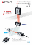
NEW
CMOS Multi-Function Analogue Laser Sensor
IL Series
A wide lineup of measurement ranges capable
of solving many applications, from part
differentiation to high precision measurement
Seam detection
Thickness
differentiation
Height control
Thickness
differentiation
I
Intelligent Sensor
- SERIES
Low-cost
High
Performance
INTRODUCING THE LASER APPLICATION SENSOR IL SERIES
HEIGHT/
HEIGHT DIFFERENCE
WARPAGE
THICKNESS/WIDTH
POSITIONING
VIBRATION
COUNT
VARIETY OF USES AT LOW COST
Compact and lightweight laser displacement sensor
Intelligent
I
SERIES
Rugged
Ea s y
In telligen t
High precision was achieved by using state of the art
technology and functions specifically developed for
high-accuracy measurement instruments.
Rugged
Developed for use in harsh environments, the IL Series
was designed with a robust structure.
Easy
Excellent usability makes it possible to quickly and
easily perform stable measurements without any difficult
adjustments or settings.
Low-cost
High
Performance
The intelligent I-Series consists of a high-precision sensor lineup that
realises low-cost and high performance with only the most advanced
functions for on-site operations.
Introducing the IL Series
I-
2
Intelligent Sensor
SERIES
High-Precision Head +
Multi-Function Amplifier
Intelligent
Reduced power
Increased power
When the workpiece is
highly reflective
When the workpiece
is dark
[Newly developed LSGC included] + [All-in-one design]
I
SERIES
Rugged
Easy
The stable measurement of any given target is possible by
sensing the target surface and adjusting the 600,000 times
dynamic range. Furthermore, in order to further streamline
communication with process control systems we have
installed application specific functions into the compact
amplifier.
Reflection
Power
Rugged Head Structure
Intelligent
[Die cast metal used for IP67/optical base]
I
SERIES
Rugged
Easy
The head structure was redesigned to make it rugged
enough to withstand almost any environment. In addition,
the housing is made of die cast SUS304 for added
strength and protection.
Compact Head Design +
Easy Mounting
Intelligent
20 million cycle service
life (typical)
Load (W): 250 g
Bending radius: R50 mm
Rate: 30 bends/minute
[Smallest body in its class] + [Hi-flex cable]
I
SERIES
Rugged
Easy
The IL Series has achieved the smallest head housing in its
class by adopting the unique aspherical lens. The weight of
the head is a mere 60g*. The sensor head cable is designed
with a robot cable. This cable is specifically designed for
high cycle service life and makes the sensor ideal for
robotics or other high cycle applications.
90°
(One bend is a cycle whereby the
cable is bent from left to right and
then from right to left.)
R
Free Cut!
L
*IL-030
IL-600
Reference distance
Measurement range
Display Resolution
Repeatability
600 mm
200 to 1000 mm IL-300
50 µm
Reference distance
300 µm
Measurement range
Display Resolution
Repeatability
300 mm
160 to 450 mm
10 µm
50 µm
IL-100
Reference distance
Measurement range
Display Resolution
Repeatability
100 mm
75 to 130 mm
2 µm
IL-065
10 µm
Reference distance
Measurement range
Display Resolution
Repeatability
65 mm
55 to 105 mm
2 µm
IL-030
4 µm
Reference distance
Measurement range
Display Resolution
Repeatability
30 mm
20 to 45 mm
1 µm
2 µm
3
The multi-function amplifier with an all-in-one design
Intelligent
I
SERIES
Rugged
Direct connection
Easy
with peripheral equipment
Vol t age / current
Peripheral equipment
analogue o u tp u t
PLC, etc.
Analogue controller, etc.
Hi / Go / Lo judgement
output
Data logger, etc.
BCD out put
PC
R S232C
N e w m o d e – Th i ck n ess cal i b ration function included
3-step easy calibration
1
Step
With conventional devices, calibration had to be conducted on every individual sensor head, however, the IL Series
has a dedicated mode that allows calibration to be completed in 3 simple steps.
Bring the target close to one sensor
head and input the thickness data,
then push the set button.
2
Step
Bring the same target used in Step 1
close to the opposing sensor head and
push the set button.
3
Step
Insert a target thicker than the
target used in Step 2. Input the
thickness data. Then pushing the
set button completes calibration.
When bringing the target closer to the sensor head in Steps 1 and 2, you are compensating for the misalignments that occur during installation. To set, you can begin with either
one of the sensor heads.
A m b i e n t l i gh t e l i m i n a t i o n f u nction included
In order to counteract any ambient light interference, the IL Series automatically activates the ambient light elimination function when
the sampling cycle is set to ‘2 ms’ or ‘5 ms’, reducing the effects of ambient light.
<A>
CMOS exposed to laser
emission
<B>
CMOS not exposed to
laser emission
Emission
Laser
—
=
(Minus)
(Equals)
Off
Sampling cycle
4
The CMOS
waveform of A
The CMOS
waveform of B
CMOS waveform
(difference)
Ambient light is
present
Ambient light only
Waveform where the ambient
light has been removed
Multi-function amplifier
CALCULATION FUNCTION
Addition mode
Subtraction mode
Setting example 1
Setting example 2
Setting example 1
Setting example 2
(thickness measurement)
(width measurement)
(Measurement of height difference)
(Measuring tilt)
FUNCTION CHOICES
NPN/PNP Output Selection (judgment selection)
Bank Function
Both NPN and PNP outputs are supported. The outputs are set
the first time the user turns on the power. These settings can
subsequently be changed. Judgments are output as HIGH, GO,
or LOW.
The bank function can register up to four patterns of specific
settings.* For example, in response to a measurement target
changeover, this function allows the user to easily switch
between the patterns of registered settings.
* HIGH setting value, LOW setting value, shift value, analogue output scaling setting
Analogue Output Selection
Mounting method options
The following five types of analogue outputs can be selected.
The output is selected the first time the user turns on the power.
Both panel and DIN-rail mount units are available.
Setting
value
Description
Not output
Analogue output after the judgement value is converted to the range from 0 to 5 V.
Analogue output after the judgement value is converted to the range of ±5 V.
Analogue output after the judgement value is converted to the range from 1 to 5 V.
Analogue output after the judgement value is converted to the range from 4 to 20 mA.
The setting can be changed.
IL-1500/1550
IL-1000/1050
Panel mount type
DIN-rail mount type
Communication Unit
DL-RB1A
DL-RS1A 1.
BCD output unit
RS-232C communication unit
Use this unit when retrieving numerical
data from the IL Series to an external
device as digital data. A single
communication unit can retrieve data
from up to 8 IL Series display units via
BCD.
Use this unit when outputting digital
data to an external device with
RS-232C signals. In addition the unit
can be used to externally program the
amplifiers.
1. D-sub 9 pin connector cable (OP-81283) can be used for
connection.
5
Applications
6
Height difference measurements of a
plastic extrusion
Warpage detection in ceramic boards
Provides constant
monitoring by measuring
the height using 2
sensors simultaneously,
then calculates the
height difference using
the calculation function
in the amplifier. Reliable
detection is possible
even if the product type
or colour changes.
As the sensor head
is compact, multiple
point measurements of
small-scale boards are
possible. By calculating
the measurement data
externally, simultaneous
measurements of
positioning and warpage
are possible.
Thickness/width measurements of building
material boards
Packaging material counting
Thickness and width
can be simultaneously
measured immediately
after the extrusion
process. In addition,
man-hours for setup and
product changeovers
are reduced using the
thickness calibration
function.
Even in targets with a
large amount of shape
scatter, reliable counts
can still be achieved
by detecting rising
edges.
Accuracy checks on an automotive door
assembly
Positional control of welding beads
When assembling
automotive doors,
by simultaneously
measuring multiple
points, the assembly
accuracy can be
evaluated. Reliable
detection is possible
regardless of body
colour.
Through external
calculations of
height data from the
sensor, the device
detects the position
of the weld seam.
Welding accuracy
can be improved
via measurement
data feedback to the
welder.
Heat processing inspection of cans
Height controls of a hoop material
By observing
the expansion
displacement of a can
after heat processing,
the results of heat
processing can be
evaluated. Reliable
differentiation can still
be conducted even
if there are colour
changes in the cans.
By using a long
range type of sensor
head, it is possible to
control height of hoop
materials such as
steel plates and sheet
materials even during
transportation.
The sensor head
can be installed at
a distance of up to
1000 mm.
Differentiation of different types of plastic
components
Stacker counting & uneven checks
Reliable differentiation,
even in highly variable
small parts, using a
high-precision sensor
head. Even when the
variety changes, external
changeover of up to 4
patterns is possible by
setting items in the bank
function.
The IL Series counts
how many items are
being transpor ted
along a conveyer, in
addition to the noncontact detection of
uneven stacking in
the stacker. Reliable
detection regardless
of colour changes in
the targets.
Wire winding process
Height controls of a PC board
Prevents irregular
winding by monitoring
the traverser position.
In addition, feedback
control to the device is
possible by measuring
the volume wound into
the bobbin at the same
time.
Controls the PC board
height in the mounting
and drilling processes.
Various kinds of targets
can be reliably controlled
without being affected by
the surface colours of the
PC boards.
Detection of stage inclination prior to
furnace transportation
Wafer measurement inside an inspection
machine
Calculates the inclination
by measuring multiple
points on the stage prior
to transferring to the
furnace. Transferring the
product after correcting
the inclination allows for
consistent temperature
control.
Measures the behaviour
of each wafer in the
machine. Due to the
small head size, the IL
Series can be installed
in compact spaces. This
means the IL Series can
be installed even after
the machinery has been
set up.
Misalignment measurement and presence
detection of a wafer/glass in a cassette.
Measuring the height of a chip after
bonding
Measures the presence
and protrusion of glass in
a cassette.
Stable detection is
possible even if positional
misalignments occur
in the cassette itself
by utilising analogue
processing.
Measures the height of
the board pre-bonding
and the chip postmounting, allowing
control of the postprocessing suction
nozzle and dispenser
nozzle feedback.
7
Specification
Sensor heads
Model
IL-030
IL-065
IL-100
IL-300
IL-600
Appearance
Reference distance
Measurement range
Light source
Laser class
Output
Spot diameter (at standard distance)
Linearity 2. 3.
Repeatability 4.
Sampling rate
Operation status indicators
Temperature characteristics 3.
Enclosure rating
Ambient light 5.
Ambient temperature
Environmental
resistance
Relative humidity
Vibration
Pollution degree
Material
Weight
1.
2.
3.
4.
5.
30 mm
20 to 45 mm
65 mm
100 mm
300 mm
55 to 105 mm
75 to 130 mm
160 to 450 mm
Red semiconductor laser, wavelength: 655 nm (visible light)
Class 1 (FDA (CDRH) Part1040.10) 1.
Class 1 (IEC 60825-1)
600 mm
200 to 1000 mm
Class 2 (FDA (CDRH) Part1040.10) 1.
Class 2 (IEC 60825-1)
220 µW
Approx. 200 × 750 µm
Approx. 550 × 1750µm
±0.1% of F.S.
±0.1% of F.S.
2 µm
4 µm
560 µW
Approx. 400 × 1350 µm
Approx. ø0.5 mm
Approx. ø1.6 mm
±0.25% of F.S.
±0.25% of F.S.(200 to 600 mm)
±0.5% of F.S.(200 to 1000 mm)
±0.15% of F.S.
10 µm
50 µm
300 µm
0.33/1/2/5 ms (4 levels available)
Laser emission warning indicator: Green LED, Analogue range indicator: Orange LED, Reference distance indicator: Red/Green LED
0.05% of F.S./°C
0.06% of F.S./°C
0.06% of F.S./°C
0.08% of F.S./°C
IP67
Incandescent lamp: 5000 lux
Incandescent lamp: 7500 lux
Incandescent lamp: 5000 lux
-10 to +50°C (No condensation or freezing)
35 to 85% RH (No condensation)
10 to 55 Hz Double amplitude 1.5 mm XYZ each axis: 2 hours
3
Housing material: PBT, Metal parts: SUS304, Packing: NBR, Lens cover: Glass, Cable: PVC
Approx. 60g
Approx. 75g
Approx. 135g
The laser classification for FDA (CDRH) is implemented based on IEC 60825-1 in accordance with the requirements of Laser Notice No.50.
Value when measuring the KEYENCE standard target (white diffuse object).
F.S. of each model is as follows. IL-030: ±5mm IL-065: ±10mm IL-100: ±20mm IL-300: ±140mm IL-600: ±400mm
Value when measuring the KEYENCE standard target (white diffuse object) at the reference distance, sampling rate: 1 ms, and average number of times: 16. For the IL-300/IL-600, the sampling rate is 2 ms.
Value when the sampling rate is set to 2 ms or 5 ms.
Amplifier unit
Model
IL-1000
IL-1500
IL-1050
Panel mount
DIN-rail mount
IL-1550
Appearance
Type
Main unit/expansion unit
Head compatibility
Minimum
displayable unit
Display
Display range
Display rate
Analogue voltage output 1.
Analogue current output 1.
Bank switch input
Zero-shift input
Control input 2. Stop emission input
Timing input
Reset input
Judgement output
3.
Control output
Alarm output
Power voltage 4.
Current
Power consumption
Ambient humidity
Ambient temperature
Environmental
resistance
Vibration
Pollution degree
Material
Weight (including attachments)
DIN-rail mount
Main unit
Panel mount
Expansion unit
Compatible
IL-030: 1 µm, IL-065/IL-100: 2 µm, IL-300: 10 µm, IL-600: 50 µm
IL-030/IL-065/IL-100: ±99.999 mm to ±99 mm (4 levels selectable), IL-300/IL-600: ±999.99 mm to ±99 mm (3 levels selectable)
Approx. 10 times/sec.
±5 V, 1 to 5 V, 0 to 5 V Output impedance 100 Ω
None
4 to 20 mA Maximum load resistance of 350 Ω
Non-voltage input
Open collector output (NPN, PNP changeover possible/N.O., N.C. changeover possible)
Open collector output (NPN, PNP changeover possible/N.C.)
10 to 30 VDC ripple (P-P) 10% included, Class 2
Supplied by main unit
2300 mW or less (at 30 V: 77 mA or less) 2500 mW or less (at 30 V: 84 mA or less) 2000 mW or less (at 30 V: 67 mA or less) 2200 mW or less (at 30 V: 74 mA or less)
-10 to +50°C (No condensation or freezing)
35 to 85% RH (No condensation)
10 to 55 Hz Double amplitude 1.5 mm XYZ each axis: 2 hours
2
Case / Front sheet: Polycarbonate; Key tops: Polyacetel; Cable: PVC
Approx. 150g
Approx. 170g
Approx. 140g
Approx. 160g
1. Select and use one of ±5 V, 1 to 5 V, 0 to 5 V or 4 to 20 mA.
2. Assign an input of your choice to the 4 external input lines before using.
3. – The NPN open collector rated output is: 50 mA max./ch (20 mA when adding an expansion unit) less than 30 V, residual voltage less than 1 V (less than 1.5 V when adding over 6 units including the main unit)
– The PNP open collector rated output is: 50 mA max./ch (20 mA/ch when adding expansion units), less than power voltage, and less than 2 V residual voltage (less than 2.5 V when adding over 6 units including the main unit)
4. If there are over 6 additional expansion units, please use a power voltage of 20 to 30 V.
Sensor head cables (sold separately)
The cable does not come attached with the sensor head and must be purchased separately.
Appearance
1 cable
included
Cable length
2m
5m
10 m
20 m
Model
OP-87056
OP-87057
OP-87058
OP-87059
Weight
Approx. 80 g
Approx. 190 g
Approx. 360 g
Approx. 680 g
This connector is required if the cable is cut.
Connector used to connect to a display unit (2 pcs.)
OP-84338
8
Communication unit
Model
DL-RB1A
DL-RS1A
Appearance
Power supply voltage
Power consumption
Number of connectable sensor amplifi ers
20 to 30 VDC, including ripple, Ripple (P-P): 10% max. Class 2 (Supplied via connected sensor amplifier)
27 mA max.
25 mA max.
Up to 8 units (including main unit)
Alarm indicator lamp (red), Power indicator lamp (green)
Communication indicator lamp (green × 2), Alarm indicator lamp (red),
Power indicator lamp (green)
Communication method
Synchronization method
Transmission code
Baud rate
Data bit length
Parity check
Stop bit length
-
Full duplex
Start-stop
ASCII
2400/4800/9600/19200/38400 bps selectable (Factory-setting: 9600 bps)
8 bits/7 bits selectable (Factory-setting: 8 bits)
None/Even/Odd selectable (Factory-setting: None)
1 bit
Data delimiter
-
Data reception: automatically recognizes CR or CR+LF
Data transmission: Fixed to CR+LF
Indicator
Environment
resistance
Ambient temperature
Ambient humidity
Vibration resistance
-10 to +55°C
35 to 85%RH (No condensation)
10 to 55 Hz Double amplitude 1.5 mm XYZ each axis: 2 hours
Case/Polycarbonate
Material
Weight
Approx. 46 g
Approx. 53 g
Optional
Type
Appearance
Model
Description
To connect an additional expansion unit, use the end units
to secure the display units on both ends. When connecting
additional units, be sure to use the end units. (2 pcs.)
Weight
End unit (Optional)
OP-26751
Approx. 15g
Panel front protection cover
[Included in panel mount type amplifi er]
OP-87076
Panel mounting bracket
[Included in panel mount type amplifi er]
OP-4122
Expansion cable: 300 mm
OP-35361
Extension cable used for panel mount type amplifi er. Use this
cable if the standard cable is not long enough.
Approx. 10g
DIN-rail mounting bracket
OP-60412
The mounting bracket is used when the expansion cable is used
to connect to the panel mount type display unit, in which case a
DIN rail is not provided.
Approx. 12g
Approx. 6g
The panel front protection cover and panel mounting bracket are
included in the panel mount type amplifi er. If the supplied cover
or bracket is lost or damaged, purchase a new one.
Approx. 7g
Wiring Diagram
Brown 1.
Blue 1.
Black
White
Gray
Green
Light
blue 1.
Orange 2.
Shield 2.
Pink 3.
Yellow 3.
Pink/purple 3.
Purple 3.
10 to 30 VDC 4.
0V
HIGH judgment output
LOW judgment output
GO judgment output
Alarm output
Analogue output +
Analogue output GND
External input 1 (zero shift input)
External input 2 (reset input)
External input 3 (timing input)
1. The brown, blue, and light blue cables are not provided in a
IL-1050/IL-1550 unit (expansion unit).
The power is supplied to the expansion unit from the IL-1000/
IL-1500 unit (main unit).
2. For an analogue output, OFF (not used), 0 to 5 V, ±5 V, 1 to 5
V, or 4 to 20 mA can be selected.
3. For an external input, bank A input, bank B input, laser
emission stop input, or OFF (not used) can also be selected.
For details, refer to the User’s Manual.
4. If there are over 6 additional expansion units, please use a
power voltage of 20 to 30 V.
External input 4 (not used)
9
Dimensions
Unit : mm
Sensor heads
Mounting bracket
(supplied)
IL-030
4.8
6.6
13.8
6.5
4.8
3.5
12
3.5
22.6
0.6
29.7
3.2
38.3 24.8
ø3
42.1
48.5
13.7
Center of
emitted light
11.7
Indicator
9.1
9.5
11.7
9.1
9.5
(26)
33.5
37.9
Reference surface
for distance detection
2-M3 P= 0.5
.5
Material: SUS304
t=2.0
ø9
3.6
Center of
received light
Material: SUS304
t=1.5
30
18.3
2-ø3.5
(mounting hole)
3.2
Supplied screw (2 pcs.)
M3, P= 0.5, L=30
Material: SUS
9.4
55.2
3.5
ø4.8 cable length 160
Tip M8 connector
20
2.5˚
2.5˚
Mounting bracket
(supplied)
4.8
6.5
(min. 5)
43.7 49.7
42.1
60
6
IL-065/100
6.7 15
4.8
3.5
12
3.5
23.2
42.3
2-ø3.5
(mounting hole)
3.2
34.7
24.1
0.6
11.7
Indicator
3.6
Center of
received light
Center of
emitted light
Supplied screw (2 pcs.)
M3, P= 0.5, L=30
Material: SUS
9.5
11.6
Reference surface
for distance detection
2-M3 P= 0.5
.5
53.6
46.1
62
47.6
57.2
3.5
9.4
11.7
38.5
42.8
10.5
ø3
Material: SUS304
t=2.0
46.1
52.5
Material: SUS304
t=1.5
22.1
3.2
11.6
15.4
31.3
6
ø4.8 cable length 160
Tip M8 connector
5.5˚
20
4˚
(min. 5)
IL-300/600
9.1 9.1 18.5
Mounting bracket
(supplied)
3.8
7.5
5.3
4.5
12
4.5
42
32.4
15.5
2-ø4.4 (mounting hole)
27.2
16.4
0.6
4.5
45
4.5
20.5
Material: SUS304
t=2.0
ø4.5
2× M4 P=0.7
Indicator
20.8
55.8
57
66
ø4.8 cable length 160
Tip M8 connector
ø9
Center of
received light
Center of
emitted light
15.5
50.7
13.6
Reference surface
for distance detection
10
11.4
(min. 5)
11.6
59.1
69.8
67.1
4.5
(26)
13
57
76
Material: SUS304
t=2.0
3.6
8°
22
3.5°
8
Options
Unit : mm
Amplifier unit (DIN-rail mount type)
IL-1000/IL-1050
IL-1000
IL-1050
Cable diameter ø4.7
Cable length 2 m
28.3
18.5
8.9
Cable diameter ø4.8
38.9
17.4
42.4 37.4
135
3
(min.15)
21.6
8.9
X
°MA
When cover is open
max.109.2
42.4
° MA
X
3
42.4
20
21.6
17.4
37.4
When cover is open
max.109.2
17.6
35.4
When cover is open
max.109.2
(min.15)
76.3
17.6
20
44.7 (min.15)
15.3
4
type)
Amplifier unit (Panel mount
21.6
17.6
35.4
(min.15)
20
21.6
35.4
(min.15)
76.3
28.3
(3.4)
135
When cover(min.15)
is open
max.109.2
(min.15)
76.3
18.5
17.4
17.6
35.4
17.4
42.4 37.4
37.4
Cable diameter ø4.7
Cable length 2 m
(3.4)
X
° MA
135
(1.9)
Cable diameter ø4.8
3
Cable diameter ø4.8
20
(1.9)
Cable diameter ø4.8
28.3
18.5
AX
28.3
18.5
8.9
Cable diameter ø4.7
Cable length 2 m
°M
135
Cable diameter ø4.7
Cable length 2 m
(min.15)
76.3
Cable diameter ø4.8
Cable diameter ø4.7
IL-1500/IL-1550
Cable length 2 m
44.7
4
+0.6
45 -0
15.3
Cable diameter ø4.7
37.1
Cable length 2 m
27.4
Panel thickness
1 to 6
Cable diameter ø4.8
47.6
X=48+0.6
×
45 -0 of amplifiers) -3
(number
X
12.4
37.1
27.4
19.1
Panel thickness
1 to 6
47.6
9.7
X
min.85
12.4
45 +0.6
-0
44.7
48
19.1
17.6
19.1
48
76
9.7
22.4
9.7
19.1
min.85
+0.6
45 -0
45 +0.6
-0
44.7
22.4
17.6
76
X=48 ×
(number of amplifiers) -3
+0.6
45 -0
9.7
Communication unit (BCD output type)
DL-RB1A
DIN-rail mount
When the mounting bracket is attached
OP-60412 (Optional)
22.5
53.4
(57.8)
53.4
37.1
60.9
37.1
34-pin MIL connector
21.1
35.4
70
31.4
15
70
2-ø3.4
2 - (4.4 × 3.4)
22.5
15
Material : SPCC Steel
28.5
35.5
Communication unit (RS-232C communication type)
DL-RS1A
DIN-rail mount
When the mounting bracket is attached
OP-60412 (Optional)
22.5
(48.2) 37.2
51.3
43.8
37.2
43.8
21.1
35.4
70
31.4
15
70
2-ø3.4
2 - (4.4 × 3.4)
22.5
15
Material : SPCC Steel
28.5
35.5
11
Total Solution Lineup
CCD LASER MICROMETRE
Multi-Purpose
CCD Laser Micrometre
IG Series
❙ Repeatability of 5 µm
❙ Linearity of ± 0.1% (IG-028)
❙ Built-in position monitor
Feedback control using edge position
control
Outer diameter/deformation
measurement
Measurement of defects in a press fit
Detection of crank shaft defects
CONTACT SENSOR
High-precision Contact
Digital Sensor
GT2 Series
❙ High accuracy in the entire
measurement range
❙ Good temperature characteristics
❙ No tracking errors
❙ Absolute position detection
Resolution
0.1 µm
Accuracy
1 µm
INDUCTIVE DISPLACEMENT
Digital Inductive
Displacement Sensor
EX-V Series
❙ Resolution of 0.02% of F.S.
❙ Linearity of ± 0.3% of F.S.
❙ Ultra high-speed sampling of 25 µs
Confirmation of the die closure of an IC
molding press
Copyright (c) 2010 KEYENCE CORPORATION. All rights reserved.
Measuring the gap between rollers
IL-WW-C2-E 1021-1 E 600874 Printed in Japan
*
6
0
0
8
7
4
*