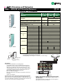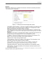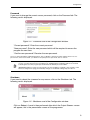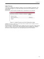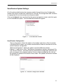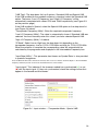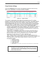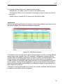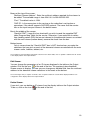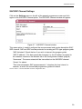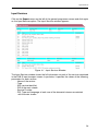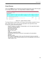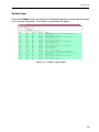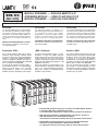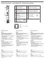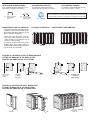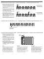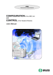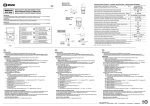
1
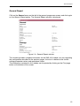
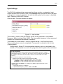
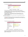
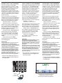
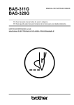
SNS-100
IP Streamer – DVB-S FTA to IP multicast
Multicast streamer for IP broadband networks. Up to eight simultaneous DVB-S satellite
television programs for Free-To-Air (FTA) encoded for streaming over IP multicast
networks.
Designed and manufactured by Messrs Ikusi of Spain. Sold and supported by
Teletechnique Beechmont in Queensland.
14 Jacaranda Court, BEECHMONT QLD 4211, Australia
Phone: +61-(0)7-3103-0750 - Fax: +61-(0)7-5604-1402
E-mail: [email protected]
Web: www.teletechnique.com - ABN 34 383 278 861
(Television on IP Networks)
«SNS» — DVB-S/S2 to IP Streaming Equipment
CE
DVB-S/S2 ➞ IP Streamers
SNS-100
SNS-101
SNS-102
Reference
5100
5101
5113
Reception
DVB-S FTA
Model
DVB-S/S2
DVB-S
FTA or MultiCrypt
(Common Interface - EN 50221)
Variable
Maximum number of de-encrypted services
—
(CAM depending)
SNMP Support — traps
No
Yes
DiSEqC equipped (vers. 1.08)
No
Yes
SNS-100
Input Section
(QPSK/8PSK))
Frequency range
MHz
950 - 2150
Input level
dBm
-65 ... -25
Input loop-through gain
0 (±1)
dB
Input symbol rate
2 ... 45
MS/s
Standard
IEEE 802.3 10/100 BaseT
Mbps
Bit rate
Output Section
(IP)
up to 100
Transmission protocols
UDP / RTP
No. of simultaneous streams
up to 8
Multicast
Yes
RF input (loop-through)
(2x) female F
DC connection
Connectors
"banana" socket
CAM entrance
—
slot
Configuration
RS 232 / DB-9
RJ-45
Ethernet output
SNS-102
General
+12
Supply voltage
VDC
Consumption
mA
260
mA
—
Max DiSEqC current
QPSK
Operating temperature
°C
0 ... +45
Dimensions
mm
230 x 195 x 32
IN
+V
●
LNB
CAM
CONTROL
SYNC
790 (DVB-S2)
300
ON - STATUS - LINK - ACT
Indicator leds
CAM slot
CAM included: 480 (DVB-S) ,,
STATUS
+12V
Each module is packed with:
- 1 F plug bridge, 64 mm length, for input tap line.
- 1 DC plug bridge, 53 mm length, for connection of +12 VDC voltage.
QPSK
QPSK
SNS-101
Ref. 5101
CAM
DVB-S
Þ IPTV
STREAMER
LAN
Link
Act
Operator's
Smart Card
SNS-101/02
MS-0908
Conax, Cryptoworks, Irdeto
KeyFly, Mediaguard, Nagravision
Viaccess, etc.
SNS Headends
An SNS headend for DVB-S/S2 to IP streaming includes:
- As many SNS streamers as there are DVB-S/S2 transponders whose
programmes one want to broadcast on the IP network. The SNS-101 or
SNS-102 must be utilized when the transponder transmits one or more
encrypted programmes that one want to de-encrypt; a CAM (Conditional
Acces Module) containing an Operator's Smart Card must fit the front
panel slot. CAM modules are not supplied by IKUSI.
- One or more CFP Power Supplies.
- One or more Rack-frames or Baseplates. The baseplates can be joined
horizontally.
- Usually, one housing unit.
The SNS streamers have two directionally coupled input ports that facilitate
simple connection of the incoming Sat-IF signal using the plug bridges supplied. Besides this, the headends with SNS-101 or SNS-102 models are able
to use Sat-IF multiswitches, what allows to change at any time the Sat-IF signal fed into each streamer without recabling the headend.
QPSK IN
QPSK IN
+VLNB
QPSK IN
+VLNB
CAM
QPSK IN
+VLNB
CAM
CONTROL
CONTROL
QPSK IN
+VLNB
CAM
CONTROL
QPSK IN
+VLNB
CAM
CONTROL
QPSK IN
+VLNB
CAM
CONTROL
QPSK IN
+VLNB
CAM
CONTROL
+VLNB
CAM
CONTROL
CAM
CONTROL
CFP-500
Ref. 4429
POWER
SYNC
STATUS
+12V
5A
SYNC
STATUS
+12V
SYNC
STATUS
+12V
SYNC
STATUS
+12V
SYNC
STATUS
+12V
SYNC
STATUS
+12V
SYNC
STATUS
+12V
SYNC
STATUS
+12V
+12V
+24V
60mA
SNS-101
SNS-101
SNS-101
SNS-101
SNS-101
SNS-101
SNS-101
SNS-101
DVB-S Þ IPTV
STREAMER
DVB-S Þ IPTV
STREAMER
DVB-S Þ IPTV
STREAMER
DVB-S Þ IPTV
STREAMER
DVB-S Þ IPTV
STREAMER
DVB-S Þ IPTV
STREAMER
DVB-S Þ IPTV
STREAMER
DVB-S Þ IPTV
STREAMER
Ref. 5101
Ref. 5101
LAN
LAN
Link
Link
Ref. 5101
LAN
Act
Act
LAN
LAN
Link
Ref. 5101
LAN
Act
LAN
Link
Ref. 5101
LAN
Act
LAN
Link
Ref. 5101
LAN
Act
LAN
Link
Ref. 5101
LAN
Act
LAN
Link
Ref. 5101
LAN
Act
LAN
Link
Act
LAN
Power
1
2
3
4 5 6
7
8
9 10 11 12 13 14 15 16
Ethernet switch
IP Network
— Example of SNS headend for eight digital satellite TV transponders.
Contains 8 SNS-101 and 1 CFP-500 power supply, all fixed on 1
BAS-900 baseplate.
This headend can feed the IP network with up to 64 TV programmes
(8 programmes at the most per streamer).
Television on IP Networks
SNS-100 (Ref. 5100)
DVB-S ➞ IP Streamer
Configuration and Settings
User Manual
EN
Configuration and Setting of the SNS-100 Streamer Module
User Manual
March 2007
Revision A
IKUSI - Ángel Iglesias, S.A.
Paseo Miramón, 170
20009 San Sebastián
SPAIN
Tel.: +34 943 44 88 00
Fax: +34 943 44 88 11
www.ikusi.com
CONTENTS
Introduction ............................................................................................................................. 4
This Manual ................................................................................................................. 4
Product Description ...................................................................................................... 4
Chapter One - Configuration of the SNS-100 Streamer ......................................................... 5
Configuration ........................................................................................................... 6-10
Save/Restore Configuration ....................................................................................... 11
General Report .......................................................................................................... 12
Chapter Two - SNS-100 Streamer Settings .......................................................................... 13
Input Settings ........................................................................................................ 14-16
Output Settings ..................................................................................................... 17-19
SAP/SDP Channel Settings ....................................................................................... 20
Chapter Three - SNS-100 Streamer Status Information ....................................................... 21
Status Information ...................................................................................................... 22
Chapter Four - SNS-100 Streamer Reports .......................................................................... 23
Input Services ............................................................................................................ 24
Output Streams .......................................................................................................... 25
System Logs .............................................................................................................. 26
3
Introduction
This Manual
This manual describes the configuration and settings programme for the SNS-100 Streamer Module.
It is the second part of the user documentation for said module, the first part of which is the Installation
and Access manual supplied in paper format.
Product Description
SNS-100 streamers are DVB-S to IP gateways designed to broadcast in multicast the services (TV or Radio
programmes) from a digital satellite reception on an IP network. The IP streams can be viewed using an IPTV
set-top box or a software video player.
SNS-100 modules have an IKUSI ClassA mechanical format. As such, they are fixed to BAS-700 / BAS-900
baseplates or to an SMR-600 rack frame, and are +12 VDC powered from a CFP module.
Characteristics
Input: 1 DVB-S transport stream (MPTS). Output: up to 8 simultaneous, IP-encapsulated services (TV or Radio programmes),
with individual multicast addresses.
Information filtering of MPEG-2 tables.
UDP & RTP transmission protocols.
Web interface for configuration and setting.
SAP & SDP protocols which facilitate automatic service selection on the user's STB and the supply of information to external
servers.
ADVANCED
PID filtering
PSI/SI parsing
Transparent ECM & EMM messaging
PAT and PMT table regeneration
Routing or blocking for CAT, NIT, SDT, EIT, TDT tables
Configurable QoS marking
Configurable Time To Live
When a connection is established between the SNS-100 streamer and the control PC, the programme
access screen will appear:
Programme Access Screen
Once the desired programme language has been chosen [Spanish (es), English (en), French (fr) ], enter
the password and click on OK.
Note: The default password — admin — can (and must) be changed as explained on page 9.
4
Chapter One - Configuration of the SNS-100 Streamer
In this Chapter
●
Configuration
●
Save/Restore
●
General Report
5
Configuration
General Configuration
Initial program screen
The first screen that appears
when the programme is
accessed contains the "Output"
window, which gives information
on the IP streams that have
been created on the module and
which may or may not be
incorporated into the output data
stream.
On the left of this screen are the
menus that access all of the
programme's functionalities.
Figure 1.1 - Initial programme screen
Click on the General menu on the left of the screen to display a dropdown list
containing the 3 options: Configuration, Save/Restore and General Report.
Click on Configuration. The Configuration window will appear :
Figure 1.2 - Identification card of the Configuration window.
Identification
The identification card (Figure 1.2) provides basic data on the SNS-100 streamer. The
different card fields are completed as follows:
6
Configuration
"Model": SNS-100. This data cannot be changed.
"Serial Number": Informational data which cannot be changed.
"Firmware Version": As above.
"Identifier": Any name that the installer or operator wishes to assign to the streamer
module can be entered here.
"Location": Enter the postcode of the installation site if required.
"Installer": The installer's identification details can be entered here.
"Contact": Then enter their contact details (telephone number, email).
"Installation date": The date on which the streamer module was installed can be
entered here.
Click on the Save button at the bottom of the window to store the information on the streamer module, this
information is then shown each time the module is accessed.
7
Configuration
Network
Click on the Network tab to configure the streamer's ethernet connection parameters.
The following card is displayed:
Figure 1.3 - Network card of the Configuration window.
"Use DHCP to get IP address": If this box is checked, the SNS-100 module will use
the DHCP protocol for assigning dynamic IP addresses. Consequently, no data
needs to be entered in the next five fields on the tab.
If the administrator of the network on which the SNS headend is installed assigns
static IP addresses, the box will not be checked and the following fields will need to
be filled in.
WARNING: If this option is activated, the IP address assigned to the streamer can
only be known by consulting the DHCP server management system.
"IP Address": Enter the IP address that you wish to assign to the streamer. This
address must fall within the range of local network addresses.
"Network mask": Enter the local network mask.
"Default gateway": Enter the IP address of this gateway. This information is only
required if you want the streamer to access Internet.
"Primary DNS server": Enter the primary server's IP address. Equally, this
information is only required if you want the streamer to access Internet.
"Secondary DNS server": Enter the same information for the secondary server.
"MAC Address": The physical address of the streamer's ethernet network card is
displayed automatically.
Once you have filled in all of the required information, click on Modify Network Configuration. If, at the last moment,
you decide to keep the current settings, click on Restore.
8
Configuration
Password
If you want to change the current access password, click on the Password tab. The
following card is displayed:
Figure 1.4 - Password card of the Configuration window.
"Current password": Enter the current password.
"New password": Enter the new password which will be required to access the
program the next time.
"Confirm new password": Re-enter the new password.
Once you have entered the required information, click on Modify so that the streamer adopts the new access
password. If, at the last moment, you decide to keep the previous password, click on Cancel.
!
Note
If you do not know the old password, i.e. the password used to access the current configuration
session, you must perform a Password Reset as explained in the Installation and Access manual.
Following this reset, the program password will be the default password: admin.
IMPORTANT: When you perform a password reset, the IP address assigned to the streamer on the
Network card (previous page) automatically changes to the default setting: http:// 92.168.1.4.
Shutdown
If you need to reboot the streamer for any reason, click on the Shutdown tab. The
following card is displayed:
Figure 1.5 - Shutdown card of the Configuration window.
Click on Reboot. A reset is then performed after which the Output Streams screen
will appear, this is the presentation screen of the programme.
9
Configuration
Update Firmware
If you wish to update the streamer's firmware, click on the Update Firmware tab. The
card displayed (Figure 1.6) shows the firmware version that the streamer has at the
present time.
(The firmware is software stored in the module which is responsible for its basic operation).
Figure 1.6 - Update Firmware card of the Configuration window.
WARNING: The firmware update file will have been previously stored on the PC hard drive. (You can
download it from http://www.ikusi.com).
Click on Browse... and select the firmware update file from the hard drive. When the file
name is in the box, click on Start. The new firmware will be installed on the streamer
and then its name will appear in the card replacing the one of the file before.
10
Save/Restore
Save/Restore System Settings
All of the data established on the streamer module through the various Configuration
window tabs can be saved onto a backup file. Inversely, the configuration data saved on
an appropriate file can be restored on streamer module.
Click on the General menu on the left of the general programme screen and click again
on the Save/Restore option. The Save/Restore window will appear:
Figure 1.7 - Save/Restore window
Save/Restore Configuration
"Save configuration": Select the option in the window and click on Start. A window
is displayed which allows you to select the destination folder for the data file for the
current streamer configuration.
"Restore Configuration": Select this option in the Save/Restore window
(Figure 1.7) and click on Start. The Restore Configuration window is displayed (Fig.
1.8) Click on Browse... and select the file containing the configuration data that you
wish to restore on the streamer module. Once you have selected the file, click on
the Upload File button at the bottom of the screen. The upload confirmation window
will be displayed.
Figure 1.8 - Restore Configuration Window
11
General Report
General Report
Click on the General menu on the left of the general programme screen and click again
on the General Report option. The General Report window is displayed:
Figure 1.9 - General Report window
This window provides complete information on the SNS-100 module, not only regarding
the configuration described in the previous pages, but also in relation to the current
settings parameter values and operational status.
The information contained in this window can be printed by clicking on the Print page
button at the bottom of the screen.
12
Chapter Two - SNS-100 Streamer Settings
In this Chapter
●
Input Settings
●
Output Settings
●
SAP/SDP Channel Settings
13
Input
Input Settings
The SNS-100 module settings are grouped into three sections or categories: Input,
Output and SAP/SDP Channel. Click on the Settings menu on the left side of the general programme screen. A drop down list with the three option for this menu is displayed:
Input, Output and SAP/SDP Channel.
Click on Input. The Input window will appear:
Figure 2.1 - Input window
This window is used to enter the settings values for two parameters: Intermediate
Frequency (MHz) and Input Rate (MS/s). The intermediate frequency is the transposed
frequency of the desired transponder's frequency.
The window has 3 main boxes —the first three at the top— and 5 auxiliary boxes.
These auxiliary boxes are only completed if Transponder is selected in the first box
("Setting Mode").
"Setting Mode": Select IF if the intermediate frequency value is calculated by the
installer, or Transponder if you wish the programme itself to perform the calculation.
IF CALCULATION
The SNS-100 streamer's input frequency band is 950-2150 MHz, known as "satellite
intermediate frequency" or simply "IF". The value to enter for a particular transponder can
be obtained by subtracting the transponder's frequency from the LNB local oscillator
frequency.
The operational frequencies are the following:
- Satellite transponder frequency band: 10700-12750 MHz
- Local Oscillator frequency on Standard LNB's. Two possible values:
9750 MHz for 10700-11700 MHz input frequencies (low band)
10600 MHz for 11700-12750 MHz input frequencies (high band)
- Example of the calculation for FI relating to the WDR program transponder on the
Astra satellite:
Transponder frequency: 11836 MHz
IF (intermediate frequency): 11836 - 10600 = 1236 MHz
14
Input
"IF" setting mode is selected:
Figure 2.2 - Input Window — IF Mode
Only the second and third boxes of the window need now be completed :
"Intermediate Frequency (MHz)": Enter the value calculated for the transposed
intermediate frequency of the transponder's frequency in the box. The latter can be
found in specialist magazines.
"Input Rate (MS/s)": This parameter, best known and Symbol Rate, is also
provided in specialist magazines. Enter the value in MS/s (megasymbols per
second) or MegaBaud.
Once the data is entered, click on Save so that the streamer adjusts to the intermediate frequency and the input
rate shown in the respective boxes.
"Input signal": This indicates whether the streamer module has synchronised (✓)
or not (✖) with the input signal. If it has not synchronised, check the settings values
entered in the second and third boxes.
"Transponder" setting mode is selected:
Figure 2.3 - Input window — Transponder Mode - LNB Standard
In this case, the programme will itself complete the second box "Intermediate
Frequency (MHz)", based on the data entered in the last 5 boxes (the auxiliary
boxes), as indicated next:
15
Input
"LNB Type": The drop down list has 2 options: Standard LNB and Special LNB.
If the LNB installed on the parabolic antenna is standard, select the Standard LNB
option. The boxes "Low LO Frequency" and "High LO Frequency" will be
automatically completed with values 9750 and 10600 respectively (see Figure 2.3
on the previous page).
If the LNB installed is Special, select the Special LNB option on the drop down list
(see Figure 2.4 below).
"Transponder Frequency (MHz)": Enter the required transponder frequency.
"Low LO Frequency (MHz)": The value is automatically shown if Standard LNB was
selected. You must manually enter this value if you have selected Special LNB.
"High LO Frequency (MHz)": As above.
"IF Band": Select Low or High from the drop down list depending on the
transponder frequency: low for 10700-11700 MHz and high for 11700-12750 MHz.
When the selection is complete the corresponding value will automatically be
calculated by the programme and displayed in the Intermediate Frequency box.
"Input Rate (MS/s)" : This parameter, best known as Symbol Rate, is also provided
in specialist magazines.
Once the different data values have been entered, click on Save so that the streamer adjusts to the intermediate
frequency and the input rate shown in the 2nd and 3rd boxes of the window.
"Input signal": This indicates if the streamer module has synchronised (✓) or not
(✖) with the input signal. If it has not synchronised, check the settings values that
appear in the second and third boxes.
Figure 2.4 - Input window — Transponder Mode - Special LNB
16
Output
Output Section Settings
Click on the Settings menu on the left of the general programme screen and click
again on the Output option. The Output windown will appear:
Figure 2.5 - Output window
This window is used to select and configure the required services (TV or Radio
programs) from the DVB-S input transport stream as IP streams. The window displays
three boxes at the top, and in the centre it displays a table showing the IP streams
already configured and which may or may not be transmitted by the streamer module
(see NOTE below). For each stream it shows the multicast address and the different
parameters such as the PID of the main stream or the total bandwidth in Mbps.
"Protocol": The drop down menu offers two options : UDP and UDP/RTP. UDP is a
transport protocol which is not connection oriented and is particularly useful for
streaming. UDP/RTP adds extra data fields so that the data flow is served at the
correct speed for its projection in real time.
"Time To Live": Is a parameter used to restrict the stream multicasting range. A
number between 1 and 255 is entered in this box. Each time that an IP stream
passes through a router, the TTL is reduced by one unit. The stream will be
rejected by any router when the TTL value is reduced to zero.
"QoS": Quality of Service. The drop down list offers five differentiated service
options or Diffserv. These options relate to the priority that you wish to assign to the
streaming packets on their routes through switches or routers that are QoS
management capable:
1 Maximum priority
2 High priority video
3 Low priority video
4 Video and voice
5 Best effort (best effort made to correctly deliver the video data and the associated audio data)
NOTE: Configured IP Streams are those that have been created in the manner
described on the following page. These streams may or may not be
incorporated into the data stream depending on whether their corresponding
ON/OFF boxes in the first column are checked or not. The number of checked
boxes cannot be more than 8.
17
Output
The Output window allows you to perform three actions:
- Add Stream: This adds a new IP stream to the display table.
- Edit Stream: Allows you to change the parameters of the IP stream on the display table.
- Delete Stream: Deletes an IP stream from the display table.
Add Stream
Click on the Add Stream button at the bottom of the Output window (see Figure 2.5 on
the previous page). The Add Stream window is displayed:
Figure 2.6 - Add Stream window
The window shows all of the input DVB-S transport stream services, including different
details (name, type, identifier, main PID, provider). Highlighted in orange are those
services which are already configured as IP streams (seen in the display table in the
Output window) and highlighted in green are those which are not yet configured.
To add a stream to the display table, select the button for the corresponding service in
the first column. The line will be highlighted in pink and at the bottom of the screen a
group of boxes will appear which relate to the elemental streams associated with the
main stream of the service.
The boxes at the top and middle of the screen will now be completed, and the elemental streams at the bottom will be configured:
18
Output
Boxes at the top of the screen:
"Multicast Stream Address": Enter the multicast address required for the stream to
be added. The available range is from 224.0.0.0 to 239.255.255.255.
"Port": The default value is 1234.
"SAP ID": Is the name given to the service on the subscriber's set-top box or
reproducer, if the device supports SAP/SDP protocol. The name that the service
has on the input transport stream is the default name.
Box in the middle of the screen:
"Send full PMT": Leave this box checked if you wish to send the complete PMT
table (Program Map Table) for the service. Otherwise, if you would like to refrain
from sending certain PIDs that are not relevant to the elemental streams associated
with the main stream (bottom boxes) remove the check from the box.
Bottom boxes:
Only in cases where the "Send full PMT" box is NOT checked can you make the
selections that you wish on each of the elemental streams associated with the main
stream: audio, subtitles, teletext, etc.
Once all data is entered and the appropriate selections have been made, click on Update to add the new IP stream
to the display table in the Output window.
Edit Stream:
You can change the parameters of an IP stream displayed in the table on the Output
window. Click on the icon
at the end of the line. The previously described Add
Stream screen is displayed, where you can change any editable field, from the multicast
address to the elemental stream selections in the boxes at the bottom.
Once all changes that you require are made, click on Update and the IP stream will be displayed with its new
configuration in the display table in the Output window.
Delete Stream:
If you wish, you can delete an IP stream from the display table on the Output window.
To do so, click on the icon
at the end of the line.
19
SAP/SDP Channel
SAP/SDP Channel Settings
Click on the Settings menu on the left of the general programme screen and click
again on the SAP/SDP Channel option. The SAP/SDP Channel window will appear:
Figure 2.7 - SAP/SDP Channel window
This menu option is used to configure the announcement and service description SAP/
SDP channel. SAP and SDP are two protocols for creating an EPG type program guide.
"SAP Activated": Check the box if you wish to transmit the program guide.
"SAP IP address": This data cannot be changed. It is the IP address assigned to
the streamer module on the Network tab in the Configuration window (page 8).
"Username": The name entered will be transmitted on the SAP/SDP channel.
"Group": As above.
"Time interval between SAP announcements": Introduce the time interval, in
seconds, at which the transmitted programmes guide will refresh.
Click on Save to save the SAP/SDP channel configuration data.
20
Chapter Three - SNS-100 Streamer Status Information
In this Chapter
●
Status Information
21
Status Information
Status Information
Click on the Status menu on the left of the general programme screen and click again
on the Status Information option. The Status Information window appears:
Figure 3.1 - Status Information window
This window gives you information on the existence of alarms for module operations
and on the importance reception and transmission parameters:
"Hardware Alarm" : Indicates whether there is an anomaly in the modules circuitry.
A ✓ mark indicates correct status or operations and a cross ✖ warns of an alarm
situation.
"Input": Indicates whether there is (✓) synchronisation or not (✖) with the input
signal. In cases where there is not synchronisation, check the settings made in the
Input Settings (pages 14 to 16).
"BER": Expresses in scientific notation the channel BER value for the input signal.
"C/N (dB)": The value in dB of the carrier/noise ratio of the input signal.
"Number of Streams": Number of IP streams currently transmitted by the SNS-100
module.
«Bandwidth»: Value in Mbps.
"Information Sent (MB)": Expresses in scientific notation, the amount of information
(in megabytes) which has been transmitted by the internal web server since the last
module reset.
"Information Received (MB)": The same for information received.
22
Chapter Four - SNS-100 Streamer Reports
In this Chapter
●
Input Services
●
Output Streams
●
System Logs
23
Input Services
Input Services
Click on the Reports menu on the left of the general programme screen and click again
on the Input Services option. The Input Services window appears:
Figure 4.1 - Input Services Window
The Input Services window shows the full information on each of the services contained
in the DVB-S input transport stream. In particular, it specifies the values of the following
parameters for each service:
- Name of the service
- Type
- SID (service identifier)
- PID of the main stream
- Service Provider
- PID, Type and Language of each one of the elemental streams associated
with the main stream
24
Output Streams
Output Streams
Click on the Reports menu on the left of the general programme screen and click again
on the Output Streams option. The Output Streams window will appear:
Figure 4.2 - Output Streams window
The Output Streams window shows all IP streams that have been created for this module. These streams may or may not be incorporated in the output data stream.
For each IP it shows the following details:
- ON/OFF (whether the stream is incorporated or not in the output data stream)
- IP Stream (multicast address)
- SID (service identifier)
- PID of the main stream
- Name of the service
- Type
- Total output bandwidth in Mbps
- SAP ID (name with which the service is announced on the subscriber's
receiver)
- Service Provider
- PID, Type and Language of each one of the elemental streams associated
with the main stream, indicating whether they are incorporated into the main IP
output stream or not.
25
System Logs
System Logs
Click on the Reports menu on the left of the general programme screen and click again
on the System Logs option. The System Logs window will appear:
Figure 4.3 - System Logs window
26
IKUSI - Ángel Iglesias, S.A.
Paseo Miramón, 170
20009 San Sebastián
SPAIN
Tel.: +34 943 44 88 00
Fax: +34 943 44 88 11
www.ikusi.com
ER-0149/1996
EC-Declaration of Conformity
marking
We, Manufacturer
IKUSI, Angel Iglesias, S.A.
Paseo Miramón, 170
E-20009 San Sebastián, Spain
declare that the product
DVB-S ➞ IP Streamer
SNS-100
EMC
is in conformity with
Council Directive 89/336/EEC (EMC Directive)
Standards to which conformity is declared :
x EN 55022:1998
Information Technology Equipment. Radio disturbance characteristics. Limits and methods of measurement.
x EN 55024:1998
Information Technology Equipment. Inmunity characteristics. Limits
and methods of measurement.
Marco A. Domínguez
San Sebastián, January 26/2007
R&D Manager
MODULO STREAMER — DVB-S EN ABIERTO A IP
STREAMING MODULE — FREE-TO-AIR DVB-S TO IP
MODULE STREAMER — DVB-S EN CLAIR VERS IP
SNS-100
(Ref. 5100)
MANUAL DE INSTALACION Y ACCESO / INSTALLATION AND ACCESS GUIDE / NOTICE D'INSTALLATION ET ACCÈS
APPLICATION
The SNS-100 streamers are DVB-S to IP
gateways designed to broadcast in multicast on
an IP network the services (TV or Radio
programmes) issued from digital satellite
reception. The IPTV streams can be viewed
using a set-top box or a software video player.
APPLICATION
Les streamers SNS-100 sont passerelles DVB-S
vers IP dessinées pour diffuser en multicast dans
un réseau IP les services (chaînes TV et Radio)
en provenance de réception satellite numérique.
Les streams IPTV peuvent être visionnés avec
une set-top box ou un logiciel lecteur de vidéo.
CONFIGURATION AND SETTING MANUAL
This manual is supplied on PDF-format in the
attached CD-ROM.
MANUEL DE CONFIGURATION ET REGLAGE
Ce manuel esf fourni en format PDF dans le
CD-ROM ci-joint.
Estaciones «SNS»
«SNS» Headends
Stations «SNS»
Una estación modular SNS incluye tantos
streamers como transport streams DVB-S
haya con servicios que se desean difundir en
la red IP, y uno o más módulos de alimentación. Los módulos se montan en las basessoporte de fijación mural BAS-700 / BAS-900
ó en el soporte-rack SMR-600.
A través de los puertos RJ-45 de salida —
un puerto por streamer— la estación proporciona a la red IP hasta 8 x n servicios
encapsulados IP, siendo n el número de
módulos streamers instalados en la estación.
A modular SNS headend includes as many
streamers as there are DVB-S transport
streams whose services you want to broadcast
on the IP network, and one or more power
supplies. The modules are placed on the wall
fixing BAS-700 / BAS-900 baseplates or the
SMR-600 rack-frame.
The RJ-45 output ports of the headend —one
port per streamer— feed the IP network with
up to 8 x n IP-encapsulated programmes,
being n the number of streaming modules
installed in the headend.
Une station modulaire SNS inclut autant de
streamers qu'il y ait transport streams DVBS dont les services l'on désire diffuser dans
le réseau IP, et un ou plus de modules
d'alimentation. Les modules sont montés sur
les platines à fixation murale BAS-700 / BAS900 ou dans le cadre-rack SMR-600.
À travers les ports RJ-45 de sortie —un port
par streamer— la station rapporte au réseau
IP jusqu'à 8 x n services (chaînes) encapsulés
IP, étant n le nombre de modules streamers
installés dans la station.
APLICACION
Los streamers SNS-100 son pasarelas DVB-S
a IP diseñadas para difundir en multicast sobre
una red IP los servicios (cadenas TV y Radio)
procedentes de recepción satélite digital. Los
streams IPTV pueden ser visionados mediante
un set-top box o un software reproductor de
vídeo.
MANUAL DE CONFIGURACION Y AJUSTE
Este manual se suministra en formato PDF
en el CD-ROM adjunto.
QPSK IN
QPSK IN
QPSK IN
QPSK IN
QPSK IN
VLNB
VLNB
QPSK IN
VLNB
VLNB
VLNB
L
CONTRO
IKUSUP
L
CONTRO
VLNB
OL
CONTR
OL
CONTR
OL
CONTR
SYNC
OL
CONTR
SYNC
SYNC
SYNC
CFP-700
SYNC
SYNC
+12V
STATUS
+12V
-100
SNS
Ref. 5100
-100
SNS
Ref. 5100
+12V
5A
-100
SNS
Ref. 5100
60 mA
+18V
mA
-100
SNS
Ref. 5100
300
(22 kHz)
-100
SNS
Ref. 5100
LAN
+18V
mA
LAN
LAN
Link
300
Link
Link
Þ IPTV
DVB-S
ER
STREAM
LAN
LAN
Þ IPTV
DVB-S
ER
STREAM
LAN
300
(22 kHz)
-100
SNS
Ref. 5100
Þ IPTV
DVB-S
ER
STREAM
Þ IPTV
DVB-S
ER
STREAM
Þ IPTV
DVB-S
ER
STREAM
Þ IPTV
DVB-S
ER
STREAM
+13V
mA
+12V
+12V
+12V
+12V
POWER
+24V
STATUS
STATUS
STATUS
STATUS
STATUS
Link
Link
Link
Act
Act
Act
Act
Act
Act
+13V
mA
300
I
TOT (MAX)
:700 mA
— Estación SNS de fijación mural para 6 canales TV Satélite Digital. Contiene
6 streamers SNS-100 y 1 Alimentador CFP-700.
La estación puede suministrar a la red IP hasta 48 streams IPTV multicast.
— SNS wall-fixing headend for 6 Digital Satellite TV channels. Contains 6
SNS-100 streamers and 1 CFP-700 Power Supply.
The headend can feed the IP network with up to 48 multicast IPTV streams.
— Station SNS de fixation murale pour 6 canaux TV Satellite Numérique.
Contient 6 streamers SNS-100 et 1 Alimentation CFP-700.
La station peut fournit au réseau IP jusqu'à 48 streams IPTV multicast.
DESCRIPCION DE PANEL / PANEL DESCRIPTION / PRESENTATION DU MODULE
1
QPSK IN
2
1
Lazo derivación entrada FI-Sat
Sat-IF input tap-loop
Boucle dérivation entrée BIS
5
Hembrillas cascada alimentación DC
DC power cascade sockets
Embases cascade alimentation CC
2
Hembrilla telealimentación LNB
LNB power socket
Embase téléalimentation LNB
6
Puerto RJ-45 - Salida stream IP
RJ-45 port - IP stream output
Port RJ-45 - Sortie stream IP
3
Puerto DB-9 para conexión de
un terminal
DB-9 port for connection of a
terminal unit
Port DB-9 pour la connexion
d'un terminal
7
LEDs de control
Control LEDs
LEDs de contrôle
4
LEDs de control
Control LEDs
LEDs de contrôle
+VLNB
CONTROL
3
4
5
SYNC
STATUS
+12V
SNS-100
LINK
ACT
Ref. 5100
DVB-S Þ IPTV
STREAMER
LAN
6
Link
7
Act
SYNC
STATUS
RJ-45 port
1
2
3
6
8
1
(Tx +)
(Tx -)
(Rx +)
(Rx -)
4 , 5 , 7 , 8 (N/C)
INDICADORES LED
LED INDICATORS
INDICATEURS LED
SYNC
SYNC
SYNC
Las indicaciones del led SYNC deben
atenderse cuando haya terminado el
proceso de ajuste del streamer.
- Si luce verde permanente, el stream IP de
salida es correcto.
- Si parpadea verde, no se ha adquirido la
señal de entrada.
- Si está apagado y el led STATUS
parpadea rápido rojo: error de firmware.
Indications of the SYNC led must be
attended when the setting process of the
streamer is finished :
- If it lights green permanently, the output IP
stream is correct.
- If it flashes green, the streamer has not
acquired the input signal.
- If it is off and the STATUS led flashes red
quickly: firmware error
Les indications de la led SYNC doivent être
considérées seulement quand le réglage du
module soit terminé :
- Si s'illumine verte en permanence, le
stream IP de sortie est correct.
- Si clignote verte, le streamer n'a pas
acquis le signal d'entgrée.
- Si est éteinte et la led STATUS clignote
rapidement rouge : erreur de firmware.
STATUS
STATUS
STATUS
- Si permanece apagado, el hardware
funciona correctamente.
- Luce rojo mientras el módulo está
ejecutando una operación.
- Si luce rojo permanente, hay una alarma
de funcionamiento o el módulo está
defectuoso.
- If it is off, the hardware works correctly.
- It lights red while the module is carrying
out an operation.
- If it lights permanently red , there is an
operatigng alarm or the module is
damaged.
- Si est éteinte, le hardware marche
correctement.
- S'illumine rouge pendant que le module est
exécutant une opération.
- Si s'illumine rouge en permanence, il y a
une alarme de fonctionnement ou le
module est défectueux.
LINK
LINK
LINK
- Luce verde permanente si hay enlace
ethernet.
- Si está apagado, no hay enlace ethernet.
- It lights green permanently if there is
ethernet link.
- If it is off, there is not ethernet link.
- S'illumine verte en permanence s'il y a de
liaison éthernet.
- Si est éteinte, il n'y a pas de liaison éthernet.
ACT
ACT
ACT
- Parpadea verde cuando hay actividad
ethernet.
- Si está apagado, no hay actividad
ethernet.
- If flashes green when there is ethernet
activity.
- If it is off, there is not ethernet activity.
- Clignote verte quand il y a d'activité
éthernet.
- Si est éteinte, il n'y a pas d'activité éthernet.
Especificaciones técnicas / Technical specifications / Données techniques
Frecuencia de entrada
Input frequency
Fréquence d'entrée
950-2150 MHz
Número de streams simultáneos de salida
Number of simultaneous output streams
Nombre de streams simultanés de sortie
Nivel de entrada
Input level
Niveau d'entrée
-65...-25 dBm
Tipo de dirección IP de los streams
IP address type of the streams
Type d'adress IP des streams
Multicast
Tensión de alimentación
Power voltage
Tension d'alimentation
+12 VDC
260 mA
Ganancia lazo de entrada
Input loop-through gain
Gain boucle d'entrée
0 (±3) dB
Velocidad de símbolo de entrada
Input symbol rate
Débit de symbole d'entrée
2...45 MS/s
Consumo
Consumption
Consommation
Velocidad de bit de salida
Output bit rate
Débit de sortie
≤ 100 Mbps
Temperatura de funcionamiento
Operating temperature
Températures de fonctionnement
Features
Características
●
●
●
●
●
Entrada: 1 transport stream DVB-S
(MPTS). Salida: hasta 8 servicios
(cadenas) simultáneos, encapsulados IP,
con direcciones individuales multidifusión.
Filtrado de la información contenida en las
tablas MPEG-2.
Protocolos de transmisión UDP y RTP.
Interfaz web para la configuración y ajuste
del módulo.
Protocolos SAP y SDP para selección
automática de cadena en el STB y
suministro de información de programa a
servidores externos.
CARACTERISTICAS AVANZADAS
Filtrado PID
Análisis PSI/SI
Paso transparente de mensajes ECM y
EMM
Regeneración de tablas PAT y PMT
Paso o bloqueo de tablas CAT, NIT, SDT,
EIT, TDT
Marcado QoS configurable
TTL configurable
ASI : Asynchronous Serial Interface. Serial
transmission method for MPEG-2 streams.
CAT : Conditional Access Table
ECM : Entitlement Control Messages
EIT : Event Information Table
EMM : Entitlement Management Messages
IPTV : Internet Protocol Television
MPTS : Multiple Program Transport Stream
i
Para una correcta visualización de los
gráficos proporcionados por el programa,
se recomienda instalar en el PC de control el navegador web Mozilla FireFox
contenido en el CD adjunto.
●
●
●
●
●
≤8
0 ... +45 °C
Caractéristiques
Input: 1 DVB-S transport stream (MPTS).
Output: up to 8 simultaneous IP-encapsulated programmes with individual multicast
addresses.
Filtering of information contained in the
MPEG-2 tables.
UDP and RTP transmission protocols.
Web interface for module configuration.
SAP and SDP protocols to facilitate
automatic programme selection in the settop box and to provide programme
information to external servers.
ADVANCED FEATURES
PID filtering
PSI/SI parsing
ECM and EMM transparent passthrough
Regeneration of PAT and PMT tables
Passthrough or blockade of CAT, NIT,
SDT, EIT and TDT tables
QoS marking configurable
TTL configurable
NIT : Network Information Table
PAT : Program Association Table
PID : Packet IDentifier
PMT : Program Map Table
PSI : Program Specific Information
QoS : Quality of Service
RTP : Real-Time Transport Protocol
SAP : Service Advertisement Protocol
●
●
●
●
●
Entrée : 1 transport stream DVB-S
(MPTS). Sortie : jusqu'à 8 services
(chaînes) simultanés, encapsulés IP, avec
adresses individuelles multicast.
Filtrage du renseignement contenu dans
les tables MPEG-2.
Protocoles de transmission UDP et RTP.
Interface web pour la configuration.
Protocoles SAP et SDP pour sélection
automatique de chaîne sur la STB et
fourniture de renseignement de
programme à serveurs externes.
CARACTÉRISTIQUES AVANCÉES
Filtrage PID
Analyse PSI/SI
Passage transparent de messages ECM
et EMM
Régénération de tables PAT et PMT
Passage ou blocage de tables CAT, NIT,
SDT, EIT, TDT
Marquage QoS configurable
TTL configurable
SDP : Session Description Protocol
SDT : Service Description Table
SI : Service Information
SPTS : Single Program Transport Stream
TDT : Time and Date Table
TTL : Time to Live
UDP : User Datagram Protocol
i
i
For correct visualization of the diagrams
generated by the program, it is advisable
to install in the control PC the Mozilla
FireFox web browser contained in the
attached CD.
Pour une correcte visualisation des
schémas générés par le programme, il
est recommendable d'installer dans le PC
de contrôle le navigateur web Mozilla
FireFox contenu dans le CD adjoint.
ACCESORIOS SUMINISTRADOS
ACCESSORIES SUPPLIED
ACCESSOIRES FOURNIS
Con el módulo streamer SNS-100 se suministran los siguientes accesorios:
The SNS-100 streaming module is
packed with the following accessories:
Le module streamer SNS-100 est livré
avec les accessoires suivants :
(1x) Puente coaxial F
F plug bridge
Pont F
- El CD contiene el manual de Configuración y Ajuste en formato PDF
- The CD contains the Configuration and Setting manual in PDF format
- Le CD contient le manuel de Configuration et Réglage sur format PDF
(1x) Puente DC
DC plug bridge
Cavalier CC
(1x) CD-ROM
Les figures montrent l'emplacement des
modules dans deux stations SNS. Le
module d'alimentation doit être placé dans
l'un des bouts de l'ensemble.
SNS
BAS-900
BAS-700
FIJACIÓN DE LOS MÓDULOS EN LAS BASES-SOPORTE
FITTING THE MODULES TO THE BASE-PLATES
FIXATION DES MODULES SUR LES PLATINES
FIJACION
FITTING
FIXATION
base-soporte
base-plate
platine
DESMONTAJE
REMOVING
DÉMONTAGE
FIJACIÓN DE LOS MÓDULOS EN EL MARCO-RACK
FITTING THE MODULES TO THE RACK-FRAME
FIXATION DES MODULES SUR LE CADRE-RACK
QPSK IN
QPSK IN
QPSK IN
QPSK IN
QPSK IN
+VLNB
QPSK IN
+VLNB
+VLNB
+VLNB
+VLNB
CONTROL
CONTROL
QPSK IN
+VLNB
CONTROL
CONTROL
CONTROL
+VLNB
SYNC
STATUS
CONTROL
SYNC
CFP-700
SYNC
+12V
CONTROL
SYNC
CFP-700
POWER
SYNC
SYNC
00
SNS-1
Ref. 5100
0
SNS-10
Ref. 5100
0
SNS-10
Ref. 5100
+24V
60 mA
SYNC
+12V
300
(22 kHz)
+24V
60 mA
+13V
mA
Link
+18V
mA
300
(22 kHz)
Act
300
+13V
mA
300
I
TOT (MAX)
00
SNS-1
Ref. 5100
00
SNS-1
Ref. 5100
LAN
300
(22 kHz)
Þ IPTV
DVB-S
STREAMER
LAN
+18V
mA
LAN
LAN
LAN
+13V
mA
00
SNS-1
Ref. 5100
Þ IPTV
DVB-S
STREAMER
Þ IPTV
DVB-S
STREAMER
Þ IPTV
DVB-S
STREAMER
300
(22 kHz)
+18V
mA
Link
Link
Þ IPTV
DVB-S
STREAMER
Þ IPTV
DVB-S
STREAMER
0
SNS-10
Ref. 5100
STATUS
+18V
mA
LAN
STATUS
STATUS
STATUS
STATUS
STATUS
POWER
Þ IPTV
DVB-S
STREAMER
Link
Link
Link
Act
Act
Act
Act
300
:700 mA
Act
+13V
mA
300
LAN
Link
I
TOT (MAX)
:700 mA
Act
PMR-600
marco-rack SMR-600
rack-frame
cadre-rack
ALIMENT. / POWER SUPPLY
SNS
SNS
SNS
SNS
SNS
SNS
SNS
SNS
SNS
SNS
SNS
SNS
The pictures show the layout of the modules in two SNS headends. The power
supply module must be placed at one of
the ends of the assembly.
SNS
Las figuras muestran la disposición de los
módulos en dos estaciónes SNS. El módulo alimentador debe colocarse en uno
de los extremos del montaje.
ALIMENT. / POWER SUPPLY
ORDENAMIENTO DE LOS MÓDULOS / PLACING THE MODULES / EMPLACEMENT DES MODULES
Instalación puentes derivación entrada / Installing input tap bridges / Installation ponts dérivation entrée
Se creará 1 línea de derivación por cada
bajada de antena. El cable se conecta
a la puerta de entrada (conector superior) del primer módulo de la cascada.
El extremo libre de la(s) línea(s) debe
cargarse con 75Ω.
● 1 tap-line must be created per each
down-lead cable. The cable is connected
to the input port (upper connector) of the
first module of the cascade.
The unused port of the tap-line(s) must
be blocked with a 75Ω load.
● 1 ligne de dérivation doit être créée pour
chaque câble de descente d'antenne. Le
câble est connecté au port d'entrée
(connecteur supérieur) du premier module de la cascade.
Le port inutilisé des ligne(s) de dérivation
doit être chargé par un bouchon 75Ω.
●
FI-Sat
Sat-IF
BIS
a) 1 cable de bajada
1 down-lead cable
1 câble de descente
QPSK IN
QPSK IN
+VLNB
QPSK IN
+VLNB
QPSK IN
+VLNB
QPSK IN
+VLNB
QPSK IN
+VLNB
QPSK IN
+VLNB
+VLNB
75W
FI-Sat
Sat-IF
BIS
FI-Sat
Sat-IF
BIS
QPSK IN
QPSK IN
+VLNB
QPSK IN
+VLNB
QPSK IN
+VLNB
b) 2 cables de bajada
2 down-lead cables
2 câbles de descente
QPSK IN
+VLNB
QPSK IN
+VLNB
QPSK IN
+VLNB
+VLNB
75W
75W
Instalación puentes de alimentación +12 VDC / Installing DC bridges / Installation cavaliers d'alimentation +12 VCC
CFP-700
SYNC
POWER
STATUS
+12V
SYNC
STATUS
+12V
SYNC
STATUS
SYNC
STATUS
+12V
SYNC
STATUS
+12V
+12V
SYNC
STATUS
SYNC
STATUS
+12V
+12V
SYNC
STATUS
+12V
+12V
5A
+24V
AUX INPUT
Gain 5 dB
Módulo de Alimentación
Power Supply
Alimentation
Instalación latiguillo telealimentación LNB / Installing LNB powering jumper / Installation cordon d'alimentation LNB
Conectar un extremo del latiguillo a la
hembrilla +VLNB del módulo streamer al
que llega la bajada de antena, y el otro
a la hembrilla apropiada del módulo de
alimentación.
● Plug one end of the jumper to the +VLNB
socket of the streaming module to which
the down-lead cable arrives, and the
other end to the appropriate socket of
the power supply module.
● Enficher un bout du cordon à l'embase
+VLNB du module streamer auquel arrive
le câble de descente d'antenne, et l'autre
à l'embase approprié du module
alimentation.
●
Nota :
El modelo de módulo de alimentación
a utilizar depende del tipo de LNB
instalada. Con LNBs "universales"
debe utilizarse el modelo CFP-700,
que provee señales tensión/tono.
Con LNBs "quattro" puede utilizarse
tanto el CFP-700 como el CFP-500..
latiguillo
jumper
cordon
LNB
QPSK IN
+VLNB
CONTROL
CFP-700
SYNC
POWER
STATUS
+12V
+12V
5A
+24V
+18V
300 mA
(22 KHz)
SNS-100
Ref. 5100
DVB-S Þ IPTV
STREAMER
+13V
300 mA
(22 KHz)
+18V
300 mA
+13V
300 mA
I
TOT (MAX)
LAN
Link
Act
:700 mA
Remark :
The model of power supply module to
be used depend on the type of LNB
installed. With "universal" LNBs you
must use the CFP-700 model, which
provides voltage/tone signals.
With "quattro" LNBs you can use either
the CFP-700 or the CFP-500..
Remarque :
Le modèle de module d'alimentation à
utiliser depend du type de LNB
installée. Avec LNBs "universelles" on
devra utiliser le modèle CFP-700,
lequel procure signaux tension/ton.
Avec LNBs "quattro" on peut utiliser
tant le CFP-700 que le CFP-500..
ACCESO LOCAL A LOS STREAMERS
Una vez instalada la estación SNS,
deberán configurarse y ajustarse (*) uno
por uno todos los módulos streamers que
la componen. El proceso debe llevarse a
cabo en modo local, aun cuando
posteriormente se podrá acceder a cada
módulo desde cualquier PC de la LAN para
comprobar su estado de funcionamiento, o
variar su configuración y ajuste, u obtener
informes diversos.
Para el acceso local a los módulos se
utilizará un PC con tarjeta de red Ethernet y
un cable ethernet CAT-5E cruzado. El PC
debe estar configurado con los siguientes
parámetros de Propiedades de TCP/IP:
Dirección IP del PC : 192.168.1.1
Máscara de subred : 255.255.255.0
Empezar por el primer módulo. Conectar el
PC a su puerto LAN (RJ-45) de salida (ver
figura abajo). Iniciar el navegador web e
introducir la dirección IP inicial de fábrica
que tienen todos los streamers :
Dirección IP inicial : http://192.168.1.4
Pulsar INTRO. Aparece la pantalla de
presentación del programa de configuración y ajuste (ver abajo), en la que debe
introducirse la clave de acceso inicial de
fábrica:
Clave de Acceso inicial: admin
Pulsar INTRO. Se muestra la pantalla
inicial del programa.
LOCAL ACCESS TO THE STREAMERS
ACCÈS LOCAL AUX STREAMERS
After installing the SNS headend, you must
configure and set (*) one after the other
the streaming modules that make up the
headend. The process will be carried out in
local mode, even if you will be able to
accede later to each module from any PC
of the LAN in order to check its operating
status, to change its configuration and
setting, or to obtain diverse reports.
For local access to the modules you must
use a PC provided with Ethernet adapter
and a crossover CAT-5E ethernet cable.
The PC must be configured with the
following parameters of TCP/IP Properties:
IP address : 192.168.1.1
Subnet mask : 255.255.255.0
Open with the first module. Connect the PC
to its output LAN port (see figure below).
Start the web browser and enter the initial
factory IP address that have all streamers :
Initial IP address : http://192.168.1.4
Press INTRO. The programme presentation
screen of the configuration and setting
programme appears (see below). Then
type the initial factory access key:
Initial access key: admin
Press INTRO. The initial screen of the
programme is shown.
Une fois installée la station SNS, on devra
configurer et régler (*) un à un les modules
streamers qui la composent. Le processus
sera réalisé en mode local, bien que
postérieuremet on pourra accéder à
chaque module depuis un PC quelconque
du réseau LAN pour vérifier son état de
fonctionnement, modifier son configuration
et réglage, ou obtenir renseignements
divers.
Pour l'accès local aux modules on devra
utiliser un PC avec carte Ethernet et un
câble éthernet CAT-5E croisé. Le PC doit
être configuré avec les suivants paramètres
de Propriétés TCP/IP :
Adresse IP du PC : 192.168.1.1
Masque de sous-réseau : 255.255.255.0
Commencer par le premier module.
Connecter le PC au port LAN (RJ-45) de
sortie du premier module streamer (voir
figure en bas). Initier le navigateur web et
saisir l'adresse IP initiale que ont tous les
streamers :
Adresse IP initiale : http://192.168.1.4
Taper INTRO. Il apparaît l'écran de présentation du programme de configuration et
réglage (voir ci-dessous). Saisir le mot de
passe initial d'usine :
Mot de Passe initial: admin
Taper INTRO. Il est montré l'écran initial du
programme.
IMPORTANT
The aforementioned initial IP address of each
streamer must be changed through the
programme into another whose subnet section
be that of the LAN. It is advisable to change as
well the initial access key for accesing to the
programme.
The new IP addresses of the streamers and the
programme access key must be noted in a safe
place in order to spare to have to do an access
reset (see on next page) when you want to
accede the modules and you don't know the
current IP addresses of them and/or the access
key of the programme.
IMPORTANTE
Las mencionada dirección IP inicial de cada
streamer deberá ser cambiada desde el
programa por otra cuya sección subred sea la
de la LAN. Se recomienda cambiar asimismo la
clave inicial de acceso al programa.
Las nuevas direcciones IP de los streamers y
la clave de acceso al programa de configuración y ajuste deberán ser anotadas en sitio
seguro para evitar tener que hacer un reset de
acceso (ver en página siguiente) cuando se
pretenda acceder a los módulos y se
desconozcan las actuales direcciones IP de los
mismos y/o la clave de acceso al programa.
* The configuration and setting process is
explained in the manual supplied in the
attached CD-ROM
*El proceso de configuración y ajuste se
explica en el manual suministrado en el
CD-ROM adjunto.
QPSK IN
Les nouveaux adresses IP des streamers et le
mot de passe d'accès au programme doivent
être notés dans un place sûr afin d'éviter
devoir faire un reset d'accès (voir à la page
suivante) quand l'on prétende accéder aux
modules et ne l'on connaisse pas les actuelles
adresses IP de ceux-ci et/ou le mot de passe
d'accès au programme.
* Le processus de configuration et réglage
est expliqué dans le manuel fourni dans le
CD-ROM ci-joint.
QPSK IN
+VLNB
CONTROL
IMPORTANT
La mentionnée adresse IP initiale de chaque
streamer doit être changée depuis le
programme par une autre dont la section sousréseau soit celle du LAN. De même il est
recommendable changer le mot de passe initial
d'accès au programme.
QPSK IN
+VLNB
CONTROL
QPSK IN
+VLNB
CONTROL
+VLNB
CONTROL
CFP-700
POWER
SYNC
STATUS
SYNC
STATUS
+12V
SYNC
STATUS
+12V
SYNC
STATUS
+12V
+12V
+24V
+18V
300 mA
(22 KHz)
SNS-100
SNS-100
SNS-100
SNS-100
DVB-S Þ IPTV
STREAMER
DVB-S Þ IPTV
STREAMER
DVB-S Þ IPTV
STREAMER
DVB-S Þ IPTV
STREAMER
Ref. 5100
Ref. 5100
Ref. 5100
Ref. 5100
+13V
300 mA
(22 KHz)
+18V
300 mA
LAN
+13V
TOT (MAX)
Link
LAN
LAN
Link
LAN
Act
Act
300 mA
I
LAN
Link
LAN
Act
LAN
Link
Act
LAN
:700 mA
ethernet
CAT-5E
(crossover)
Pantalla de presentación del programa
Programme presentation screen
Écran de présentation du programme
Reset de acceso
Access reset
Reset d'accès
Cuando hay que acceder a un módulo
streamer y se desconocen su dirección IP
y/o la clave de acceso al programa, la única
salida es restaurar los valores iniciales de
fábrica señalados en la página anterior.
Para la restauración se precisa un PC y un
programa de comunicaciones tal como
HyperTerminal de Windows. Conectar el
PC al puerto CONTROL del panel frontal
del módulo, mediante un cable DB-9 Null
Modem (ver figura abajo). Inciar
HyperTerminal y configurar la conexión con
los siguientes parámetros:
- Formato: asíncrono
- Velocidad: 115 200 bps
- 8 bits
- 1 bit de parada
- No paridad
- Control flujo: ninguno
Conectar:
i) login: reset
ii) password: reset
Aparece un mensaje anunciando que se
han restaurado la Dirección IP y la Clave
de Acceso iniciales de fábrica (ver página
anterior). Hacer reset desconectando y
conectando la alimentación del módulo.
When you have to accede to a streaming
module and its IP address and/or the
programme access key are unknown, the
only solution is to restore the initial factory
values pointed on the previous page.
For restoring you need a PC and a
communication programme such as
HyperTerminal from Windows. Connect the
PC to the CONTROL port at the front panel
of the module, by using a Null Modem DB-9
cable (see figure below). Start
HyperTerminal and configure the
connection with the following parameters:
- Format: asynchronous
- Bit rate: 115 200 bps
- 8 bits
- 1 stop bit
- No parity
- Control of stream: none
Connect:
i) login: reset
ii) password: reset
A message announcing that the initial
factory values for IP Address and Access
Key (see previous page) have been
restored appears. Reset the module by
switching on-off the power.
Quand il faut accéder à un module
streamer et son adresse IP et/ou le mot de
passe du programme sont inconnus,
l'unique solution est restaurer les valeurs
initiales d'usine signalées à la page
précédente.
Pour la restauration on demande un PC et
un programme de communications tel que
l'HyperTerminal de Windows. Connecter le
PC au port CONTROL à la face avant du
module, par l'intermédiaire d'un câble DB-9
Null Modem (voir figure en bas). Initier
HyperTerminal et configurer la connexion
avec les paramètres suivants :
- Format: asynchrone
- Débit: 115 200 bps
- 8 bits
- 1 bit de stop
- Non parité
- Contrôle écoulement: aucun
Connecter:
i) login: reset
ii) password: reset
Il apparaît un message en annonçant que
l'Adresse IP et le Mot de Passe initials
d'usine (voir page précédente) ont été
restaurés. Faire reset en déconnectant et
connectant l'alimentation.
QPSK IN
QPSK IN
+VLNB
CONTROL
SYNC
QPSK IN
+VLNB
CONTROL
STATUS
SYNC
CONTROL
STATUS
+12V
QPSK IN
+VLNB
SYNC
STATUS
+12V
+VLNB
CONTROL
SYNC
STATUS
+12V
+12V
SNS-100
SNS-100
SNS-100
SNS-100
DVB-S Þ IPTV
STREAMER
DVB-S Þ IPTV
STREAMER
DVB-S Þ IPTV
STREAMER
DVB-S Þ IPTV
STREAMER
Ref. 5100
LAN
Link
Ref. 5100
LAN
Act
LAN
Link
Ref. 5100
LAN
Act
LAN
Link
Ref. 5100
LAN
Act
LAN
DB-9
null modem
Link
Act
LAN
CONEXION A LA RED LAN
CONNECTION TO THE LAN
CONNEXION AU RÉSEAU LAN
La conexión de la estación SNS a la red
LAN se lleva a cabo a través de un switch
ethernet al cual se conectará el puerto LAN
(RJ-45) de salida de cada streamer
utilizando cables ethernet CAT-5E.
Connection of the SNS headend to the LAN
is carried out through an ethernet switch to
which you must connect the LAN port (RJ45) of each streamer using CAT-5E ethernet
cables.
La connexion de la station SNS au réseau
LAN est effectuée à travers d'un switch
(commutateur) éthernet auquel on doit
raccorder le port LAN (RJ-45) de sortie de
chaque streamer en utilisant câbles
éthernet CAT-5E.
QPSK IN
QPSK IN
+VLNB
QPSK IN
+VLNB
CONTROL
QPSK IN
+VLNB
CONTROL
CONTROL
QPSK IN
+VLNB
CONTROL
QPSK IN
+VLNB
CONTROL
QPSK IN
+VLNB
CONTROL
QPSK IN
+VLNB
CONTROL
+VLNB
CONTROL
CFP-700
POWER
SYNC
STATUS
SYNC
STATUS
+12V
SYNC
STATUS
+12V
SYNC
STATUS
+12V
SYNC
STATUS
+12V
SYNC
STATUS
+12V
SYNC
STATUS
+12V
SYNC
STATUS
+12V
+12V
+24V
+18V
300 mA
(22 KHz)
SNS-100
SNS-100
SNS-100
SNS-100
SNS-100
SNS-100
SNS-100
SNS-100
DVB-S Þ IPTV
STREAMER
DVB-S Þ IPTV
STREAMER
DVB-S Þ IPTV
STREAMER
DVB-S Þ IPTV
STREAMER
DVB-S Þ IPTV
STREAMER
DVB-S Þ IPTV
STREAMER
DVB-S Þ IPTV
STREAMER
DVB-S Þ IPTV
STREAMER
Ref. 5100
Ref. 5100
Ref. 5100
Ref. 5100
Ref. 5100
Ref. 5100
Ref. 5100
Ref. 5100
+13V
300 mA
(22 KHz)
+18V
LAN
300 mA
+13V
Act
300 mA
I
TOT (MAX)
LAN
Link
Link
Act
LAN
Link
Act
LAN
Link
Act
LAN
Link
Act
LAN
Link
Act
LAN
Link
Act
LAN
Link
Act
:700 mA
Power
1
2
3
4 5 6
7
8
9 10 11 12 13 14 15 16
Ethernet Switch
LAN
Acceso a los streamers desde la LAN
El acceso a cada módulo streamer de la
cabecera puede llevarse a cabo desde
cualquier PC de la LAN introduciendo en el
navegador web la dirección IP que se
ajustó para aquél.
Pulsar INTRO. Aparece la pantalla de
presentación del programa de configuración y ajuste (ver abajo), en la que debe
introducirse la clave de acceso ("admin" u
otra si es que se cambió posteriormente).
Pulsar INTRO. Aparece la página inicial del
programa.
Access to the streamers from the LAN
You can accede to each streaming module
of the headend from any PC of the LAN.
Enter into the web browser the IP address
that was set for that module.
Press INTRO. The programme presentation
screen of the configuration and setting
programme appears (see below). Then type
the access key ("admin" or another if it was
changed later on).
Press INTRO. The initial page of the
programme appears.
Accès aux streamers depuis le LAN
L'accès à chaque module streamer de la
station peut être effectué depuis un PC
quelconque du réseau LAN. Saisir dans le
navigateur web l'adresse IP qui fut réglée
pour le module.
Taper INTRO. Il apparaît l'écran de présentation du programme de configuration et
réglage (voir ci-dessous). Saisir le mot de
passe ("admin" ou un autre s'il fut changé
postérieurement)..
Taper INTRO. Il est montrée la page initiale
du programme.
Pantalla de presentación del programa
Programme presentation screen
Écran de présentation du programme
IKUSI — Angel Iglesias, S.A.
Paseo Miramón, 170 - 20009 San Sebastián - SPAIN
Tel.: +34 943 44 88 00
Fax: +34 943 44 88 11
www.ikusi.com
ER-0149/1996
120508B