1
INSTALLATION AND
OPERATION MANUAL
ENGLISH
ACONDICIONADOR DE
AIRE
PARA HABITACIÓN TIPO
PORTÁTIL
ESPAÑOL
PORTABLE TYPE
ROOM AIR CONDITIONER
MANUAL DE INSTALACIÓN
Y FUNCIONAMIENTO
CV10CTXB
CV10CTXW
CV10CTXS
ENGLISH
Please read this manual carefully before using the product. This manual should be kept in
a safe place for handy reference.
• FOR CUSTOMER ASSISTANCE .......................................................... EN-2
• CONSUMER LIMITED WARRANTY ..................................................... EN-3
• PRECAUTIONS .................................................................................... EN-4
• LOCATION ........................................................................................... EN-7
• INCLUDED ........................................................................................... EN-7
• PART NAMES ....................................................................................... EN-8
• INSTALL WINDOW PANEL ................................................................... EN-12
• INSTALLATION AND REMOVAL OF EXHAUST HOSE ......................... EN-16
USE FOR AIR CONDITIONER
• COOL MODE ....................................................................................... EN-18
• DRY (DEHUMIDIFICATION) MODE ...................................................... EN-18
• FAN MODE ........................................................................................... EN-18
• TO CHANGE AIR FLOW DIRECTION .................................................. EN-18
• TIMER OPERATION ............................................................................. EN-21
• SLEEP OPERATION ............................................................................. EN-22
• MAINTENANCE .................................................................................... EN-23
• BEFORE CALLING FOR SERVICE ....................................................... EN-25
Declaration of Conformity
SHARP ROOM AIR CONDITIONER CV10CTXB, CV10CTXW, CV10CTXS
This device complies with Part 18 of FCC rules.
Responsible Party:
SHARP ELECTRONICS CORPORATION.
Sharp Plaza, Mahwah, New Jersey 07495-1163
TEL: 1-800-BE-SHARP
EN-1
ENGLISH
CONTENTS
FOR CUSTOMER ASSISTANCE (the United States)
To aid in answering questions if you call for service or for reporting loss or theft,
please record below the model and serial number located on the back side of
the unit.
MODEL NUMBER
SERIAL NUMBER
DATE OF PURCHASE
Dealer Name
Address
City
State
Zip
Telephone
TO PHONE: Dial 1-800-BE-SHARP (237-4277) for:
SERVICE (for your nearest Sharp Authorized Servicer)
PARTS (for your Authorized Parts Distributor)
ACCESSORIES
ADDITIONAL CUSTOMER INFORMATION
TO WRITE: For service problems, warranty information, missing items and
other assistance:
Sharp Electronics Corporation
Customer Assistance Center
1300 Naperville Drive
Romeoville, IL 60446-1091
TO ACCESS THE INTERNET: www.sharpusa.com
Please provide the following information when you write or call: model
number, serial number, date of purchase, your complete mailing address
(including zip code), your daytime telephone number (including area code)
and description of the problem.
EN-2
CONSUMER LIMITED WARRANTY
CONSUMER LIMITED WARRANTY FOR THE U.S. USERS
This warranty does not apply to any appearance items of the Product nor to the additional excluded
item(s) set forth below nor to any Product the exterior of which has been damaged or defaced, which has
been subjected to improper voltage or other misuse, abnormal service or handling, or which has been
altered or modified in design or construction.
In order to enforce the rights under this limited warranty, the purchaser should follow the steps set forth
below and provide proof of purchase to the servicer.
The limited warranty described herein is in addition to whatever implied warranties may be granted to
purchasers by law. ALL IMPLIED WARRANTIES INCLUDING THE WARRANTIES OF MERCHANTABILITY
AND FITNESS FOR USE ARE LIMITED TO THE PERIOD(S) FROM THE DATE OF PURCHASE SET
FORTH BELOW. Some states do not allow limitations on how long an implied warranty lasts, so the
above limitation may not apply to you.
Neither the sales personnel of the seller nor any other person is authorized to make any warranties
other than those described herein, or to extend the duration of any warranties beyond the time period
described herein on behalf of Sharp.
The warranties described herein shall be the sole and exclusive warranties granted by Sharp and shall be
the sole and exclusive remedy available to the purchaser. Correction of defects, in the manner and for the
period of time described herein, shall constitute complete fulfillment of all liabilities and responsibilities
of Sharp to the purchaser with respect to the Product, and shall constitute full satisfaction of all claims,
whether based on contract, negligence, strict liability or otherwise. In no event shall Sharp be liable,
or in any way responsible, for any damages or defects in the Product which were caused by repairs or
attempted repairs performed by anyone other than an authorized servicer. Nor shall Sharp be liable or in
any way responsible for any incidental or consequential economic or property damage. Some states do
not allow the exclusion of incidental or consequential damages, so the above exclusion may not apply to
you.
THIS WARRANTY GIVES YOU SPECIFlC LEGAL RIGHTS. YOU MAY ALSO HAVE OTHER RIGHTS
WHICH VARY FROM STATE TO STATE.
Your Product Model Number &
Description:
CV10CTXB, CV10CTXW, CV10CTXS
Portable Air Conditioner. Be sure to have this information available when
you need service for your Product.
Warranty Period for this Product: One (1) year parts and labor from date of purchase. The warranty period
continues for a total of five (5) years from date of purchase for the
Sealed Cooling System parts; labor and service are not provided free of
change for this additional period.
Additional Item(s) Excluded From Appearance items of the Product, filters, or accessories, or any printed
materials.
Warranty Coverage (If any):
Product which has been used for rental and/or commercial purposes.
From a Sharp Authorized Servicer located in the United States. To find
Where to Obtain Service:
the location of the nearest Sharp Authorized Servicer, call Sharp Toll
Free at 1-800-BE-SHARP.
What to Do to Obtain Service:
Contact your Sharp Authorized Servicer to obtain in-home service for
this Product.
The Servicer will come to your home, and if it is necessary to remove the
Product, the Servicer will reinstall it. Be sure to have Proof of Purchase
available.
TO OBTAIN SUPPLY, ACCESSORY OR PRODUCT INFORMATION, CALL 1-800-BE-SHARP, OR VISIT OUR
WEBSITE AT www.sharpusa.com
SHARP ELECTRONICS CORPORATION
Sharp Plaza, Mahwah, New Jersey 07495-1163
EN-3
ENGLISH
SHARP ELECTRONICS CORPORATION warrants to the first consumer purchaser that this Sharp brand
product (the “Product”), when shipped in its original container, will be free from defective workmanship
and materials, and agrees that it will, at its option, either repair the defect or replace the defective
Product or part thereof with a new or remanufactured equivalent at no charge to the purchaser for parts
or labor for the period(s) set forth below.
PRECAUTIONS
Points to keep in mind when using your unit.
WARNINGS FOR USE
• Install the unit in accordance with the installation instructions in the latter section
of this manual.
• Do not modify any part of this product.
• Do not insert anything into any part of the unit.
• Ensure the power supply used has an appropriate voltage rating.
Only use a three-pin grounded electrical AC socket rated 125V, 60Hz, and 15 amps or
more.
Use of a power supply with an improper voltage rating can result in damage to the unit
and possibly fire.
• Always use a fuse with the proper amp rating. Do not, under any circumstances, use wire, pins or other objects in place of a proper
fuse.
• In the event of any abnormality with the unit (ex. a burning smell), turn it off immediately and disconnect the power supply.
WARNING FOR POWER SUPPLY CORD
• This unit uses a plug with a built-in fuse. Read the precautions on the plug before using the unit.
• Always conduct a “Power Plug Check” before use to confirm the power plug functions normally.
• This power plug must only be plugged into an appropriate wall socket. Do not use
in conjunction with any extension cords.
• Push the power plug securely into the socket and make sure it is not loose.
• Do not pull, deform, or modify the power supply cord, or immerse it in water.
Pulling or misuse of the power supply cord can result in damage to the unit and cause
electrical shock.
• A damaged power supply cord must be replaced with a new power supply cord
obtained from the product manufacturer and not repaired. Replacement must be
performed by manufacture's service agent in order to avoid a hazard.
Radio or TV Interference
If this room air conditioner should cause interference to radio or television reception, try to
correct the interference by one or more of the following measures:
• Reorient or relocate the receiving antenna.
• Increase the separation between the room air conditioner and radio/TV receiver.
• Connect the room air conditioner into an outlet on a circuit different from that to which
the radio/TV receiver is connected.
• Consult the dealer or an experienced radio/TV technician for help.
EN-4
WARNING ABOUT GROUNDING
• Do not under any circumstances cut or
remove the round grounding pin from
this plug.
Consult a qualified electrician or serviceman if the grounding instructions are not
completely understood, or if in any doubt
as to whether the appliance is properly
grounded.
If a grounding adapter is used, make sure
the electrical box is fully grounded.
3-Pin socket
ENGLISH
• Improper use of the grounding plug can
result in the risk of electric shock.
This appliance must be grounded. In the
event of an electrical short circuit, grounding reduces the risk of an electric shock by
providing a less resistant conduit for the
electric current.
This appliance is equipped with a cord
that has a grounding wire connected to a
grounding plug. The plug must be plugged
into a socket that is properly installed and
grounded.
Grounding pin
3-Pin plug
Grounded
electrical box
Grounding adapter
Grounding wire
Screw
Tab for grounding
screw
Grounded electrical box
USAGE CAUTIONS
• Be sure to turn the unit off and disconnect the power supply cord before performing any maintenance or cleaning.
• Do not splash or pour water directly onto the unit. Water can cause electrical shock or equipment damage.
• Drainage should be performed whenever moving the unit.
If any water remains in the tank, it may spill out while being moved.
• Remove the window panel in the event of particularly adverse weather.
Extremely adverse weather may cause water to leak in through the openings.
• To ensure proper drainage, the drainage hose must have no kinks or be on a different level during dehumidification mode.
The drained water may spill out into the room.
• The temperature around the drainage hose must not be below freezing point when
used.
Drained water may freeze inside the hose, causing water inside the unit to overflow into
the room.
• Do not block the exhaust air outlet with obstacles.
Cooling performance may be reduced or stop completely.
EN-5
PRECAUTIONS
NOTES ON OPERATION
• Allow 3 minutes for the compressor to restart cooling.
If you turn the unit off and immediately restart it, allow three minutes for the compressor
to restart cooling. There is an electronic device in the unit that keeps the compressor
turned off for three minutes for safety.
• In the event of a power failure during use, allow 3 minutes before restarting the unit.
After power is reinstated, restart the unit. If the power was off for less than three minutes, be sure to wait at least three minutes before restarting the unit. If you restart the
unit within three minutes, a protective device in the unit may cause the compressor to
shut off. This protective device will prevent cooling for about 5 minutes. Any previous
settings will be cancelled and the unit will return to its initial settings.
• Low temperature operation: Is your unit freezing up?
Freezing may occur when the unit is set close to 64°F in low ambient temperature conditions, especially at night.
In these conditions, a further temperature drop may cause the unit to freeze.
Setting the unit to a higher temperature will prevent it from freezing.
• Dehumidification mode increases room temperature.
The unit generates heat during dehumidification mode and the room temperature will
rise. Warm air will be blown out from the Exhaust air outlet, but this is normal and does
not indicate a problem with the unit.
• This unit blows the warm air generated by the unit outside the room via the exhaust hose while in cool mode.
Accordingly, the same amount of air as that is blown out will enter the room from
outside through any openings into the room.
• When cooling operation is performed at high humidity conditions, water tank inside the unit may frequently become full.
When water tank inside the unit is full, the unit stops operating Buzzer will sound 8
times, LED window show error code H8. In this case, perform drainage to drain out
water within the unit.
OPERATING CONDITIONS
• The unit must be operated within the following temperature range.
Mode
Cool
Room temperature
64°F - 95°F
• A built-in safety device may cut off operation if the temperature exceeds these limits.
ENERGY EFFICIENCY TIPS
• Avoid direct sunlight.
Close blinds, drapes or shades to keep out direct sunlight while in cooling mode.
• Keep the filter clean.
Keeping the filter clean greatly aids efficient operation. A dirty filter blocks the flow of
air, making your unit work harder and less efficiently.
• Turn off unnecessary lights.
Your unit must remove the heat produced by your lights or other heat-producing appliances. Turn off any lights or appliances that are not in use.
EN-6
LOCATION
• The unit should be placed on a firm foundation to minimize
• The unit has casters to aid placement, but it should only be
rolled on smooth, flat surfaces. Use caution when rolling on
carpet surfaces. Do not attempt to roll the unit over objects.
MIN.12"
(30cm)
MIN.12"
(30cm)
MIN.12"
(30cm)
• The unit must be placed within reach of a properly rated
grounded socket.
• Never place any obstacles around the air inlet or outlet of the
unit.
• Allow at least 12" (30cm) of space from the wall for efficient
air-conditioning.
INCLUDED
Window Exhaust Adapter A
Exhaust Hose
Window Exhaust Adapter
Extension panel
Exhaust
cover
Adjustment
panel
Window
panel
Rain guard (2)
Foam seal B
(adhesive type)
Hose Clamp
Screw (8)
Hose clip (2)
Bracket
Rubber plug
Insect guard net
Power cord
hook (2)
Remote control
Drain hose
Battery (2)
(AAA.1.5V)
SUGGESTED TOOLS FOR WINDOW PANEL INSTALLATION
1. Screw driver (medium size Phillips)
2. Tape measure or ruler
3. Knife or scissors
4. Saw (In the event that the window panel needs to be cut down in size because the window is too
narrow for direct installation.)
EN-7
Foam seal A
Manual
ENGLISH
noise and vibration. For safe and secure positioning, place
the unit on a smooth, level floor strong enough to support
the unit.
STRUCTURE
1
Front
2
3
4
5
6
7
8
1
2
3
4
5
6
7
8
9
10
11
12
13
14
15
16
17
18
19
20
21
Control panel and display lamp
Remote control signal receiver
window
Handle
Remote controller box
Air outlet
Vertical louvers
Horizontal louvers
Wheel
Air inlet
Grill
Air outlet
Air inlet
Power cord hook
Power cord
Window exhaust adapter (down)
Rain guard
Insect guard net
Window exhaust adapter (up)
Exhaust hose
Joint
Remote control
Rear
9
17
16
18
19
20
10
11
12
15
14
13
EN-8
21
INSTALL POWER CORD HOOK
• Attach the hooks to the back of air conditioner with the screws.
ENGLISH
hook
screw
• When storing or moving the unit, wind the power cord around the hooks.
EN-9
INSTALL DRAINAGE HOSE
Drainage hose must be installed before using, otherwise blockage of drain may occur
and normal run of unit may be affected.
1
Remove drain cap from drain port.
2
Attach the drain hose clamp to the back panel of the air conditioner near the
drain port with the screw.
B
A. Drain cap
B. Drain port
A B
A
A. Drain port
B. Drain hose clamp
3
Attach one end of the drain hose to the drain port with the clip.
4
Insert the rubber plug into the other end of the drain hose and secure
with clip.
E
D
A
B
A. Rubber plug
B. Drain port
C. Drain hose
D. Drain hose clip
E. Drain hose clamp
C
EN-10
In this case, plug out drain hose from fixing clamp,unsecure the clip, pull out the
rubber plug from the drain hose, then drain out water in tank. Then reinstall the
drainage hose.
The unit will resume running after compressor stops for 3 minutes.
A. Drain port
B. Drain hose clamp
A B
EN-11
ENGLISH
When COOL or DRY (DEHUMIDIFICATION) is running, condensation will drain to
water tank. When water tank is filled, Buzzer will sound 8 times, LED window show
error code "H8".
INSTALL WINDOW PANEL
Installation in a double-hung sash window
1
Hole
Insect guard net
Connect the rain guards to the insect
guard net.
Rain guard
Insert all three projections on each rain
guard into the holes in the insect guard net.
Side “A” will now be at the top, as indicated
in the diagram.
Projection
the guard combined above to
2 Attach
the window panel.
Push the insect guard net firmly to ensure
that its four projections fit into the holes in
the window panel.
Side “A” will now be at the top, as indicated
in the diagram.
"A"
Saliente
Panel de ventana
"A"
Cut the foam seal A to the proper
3 length
and attach it to the window
sill.
Foam seal A
(adhesive type)
the window panel to the
4 Attach
window sill.
Exhaust cover
If the inner width of the window is between
22"(559mm) and 24"(609mm) inclusive
The window panel cannot be installed in
windows less than 22" (559mm) wide, as
you will be unable to shut the exhaust cover.
Window
panel
(1) Remove the adjustment panel from
the window panel, and cut the window
panel to the same width as the window.
Cut
Adjustment
panel
(2) Open the window sash and place the
window panel on the window sill.
(3) Secure the window panel to the window
sill with 2 screws.
Window panel
22"-24"
EN-12
Window sill
If the inner width of the window is between
24"(609mm) and 36.8"(934mm) inclusive.
ENGLISH
(1) Open the window sash and place
the window panel on the window sill.
(2) Slide the adjustment panel to fit the
window frame width.
(3) Secure the window panel to the sill
with 3 screws.
If the inner width of the window is between
36.8"(934mm) and 48"(1219mm) inclusive.
(1) Attach the extension panel to the
adjustment panel.
24"-36.8"
Extension panel
(2) Open the window sash and place
the window panel on the window
sill.
(3) Slide the adjustment and extension
panels to fit the window frame
width.
(4) Secure the window panel to the window sill with 4 screws.
36.8" - 48"
Foam seal A (adhesive type)
the foam seal (adhesive type)
5 Cut
A and B to the proper length and
attach it to the window panel.
Attach foam seal A to the window panel
and extension panel, and attach foam
seal B to the adjustment panel.
Close the window sash securely
6 against
the Window panel.
Cut the foam seal to an appropri7 ate
length and seal the opening
between the top of the inner window sash and the outer window
sash.
8 Attach the bracket with a screw.
EN-13
Bracket
INSTALL WINDOW PANEL
Installation in a sliding sash window
1
2
"A"
Connect the rain guards to the insect
guard net.
Insert all three projections on each rain
guard into the holes in the insect guard net.
Side “A” will now be at the top, as indicated
in the diagram.
Attach the guard combined above to
the window panel.
Push the insect guard net firmly to ensure
that its four projections fit into the holes in
the window panel.
Side “A” will now be at the top, as indicated
in the diagram, when it is installed in the
window.
Insect guard net
Hole
Projection
Rain guard
Window panel
"A"
Projection
Cut the foam seal A (adhesive type)
3 tothe
the proper length and attach it to
window frame.
Foam seal A
the window panel into the win4 Install
dow frame.
Make sure that the exhaust cover is
attached to the window panel.
Exhaust cover
If the inner width of the window is between
22"(559mm) and 24"(609mm) inclusive
The window panel cannot be installed in
windows less than 21.3" (540mm) high,
as you will be unable to shut the exhaust
cover.
Window
panel
Adjustment
panel
(1) Remove the adjustment panel from
the window panel, and cut the window
panel to the same width as the window.
(2) Open the window sash and place the
window panel on the window sill.
(3) Secure the window panel to the window
sill with 2 screws.
EN-14
Cut
Window
panel
22"-24"
If the inner width of the window is between
24"(609mm) and 36.8"(934mm) inclusive.
Adjustment panel
ENGLISH
(1) Open the window sash and place the
window panel on the window sill.
(2) Slide the adjustment panel to fit the
window frame width.
(3) Secure the window panel to the sill
with 3 screws.
If the inner width of the window is between
36.8"(934mm) and 48"(1219mm) inclusive.
24"- 36.8"
Extension panel
(1) Attach the extension panel to the
adjustment panel.
(2) Open the window sash and place the window panel on the window sill.
(3) Slide the adjustment and extension
panels to fit the window frame width.
(4) Secure the window panel to the window sill with 4 screws.
36.8"- 48"
the foam seal (adhesive type) A
5 Cut
and B to the proper length and attach it to the window panel.
Attach foam seal A to the window panel
and extension panel, and attach foam seal
B to the adjustment panel.
Close the window sash securely
6 against
the Window panel.
7
Cut the foam seal to an appropriate
length and seal the opening
between the side of the inner
window sash and the outer window
sash.
8 Attach the bracket with a screw.
EN-15
Foam seal A
(adhesive type)
Bracket
INSTALLATION AND REMOVAL OF EXHAUST HOSE
Installation of the exhaust hose
Window exhaust
adapter
Attach the window exhaust
1 adapter
B and C to the exhaust
hose.
Extend both ends of the exhaust hose
and insert them into the window exhaust adapter A respectively, and turn
them until they stop. Make sure they
are securely attached.
Exhaust hose
Window exhaust adapter A
the window exhaust
2 Attach
adapter A to the unit.
1
Insert the two projections on the window exhaust adapter A into the two
holes on the unit, and firmly attach
them to each other.
2
3 Attach the exhaust hose.
Insert the exhaust hose to the window
exhaust adapter in the window panel
and turn it to lock it in place.
Window exhaust
adapter
The exhaust hose should be as short as possible for operational
efficiency; however, it must not be twisted or bent.
Unacceptable
Acceptable
EN-16
Acceptable
Removal of the exhaust hose
ENGLISH
Remove the exhaust hose from
1 the
window exhaust adapter.
Exhaust hose
window exhaust
adapter
Remove the window exhaust
2 adapter
A from the unit.
Lift up and remove the window
exhaust adapter A from the unit by
pushing down on the two projections.
EN-17
1
2
CONTROL PANEL DISPLAY & OPERATING INSTRUCTIONS
CONTROL PANEL & DISPLAY
Temperature selection button
LED window
COOL mode lamp Receiver window
DRY
mode lamp
FAN Speed lamp
ON/OFF button
FAN mode lamp
MODE button
Fan speed button
OPERATING INSTRUCTIONS
When pressing key, buzzer makes a sound, indicator lamp shows relevant
state for 2 seconds.
1.
ON/OFF Button
Press the button once to manually turn the unit on. Press once more to turn the unit off.
2.
"+" , "-" Button
In COOL mode, press "-" once, the set temperature will decrease 1º C( F) , press "+" once,
the set temperature will increase 1ºC ( F). The set temperature range from 16º C to 30º C (61º
F to 86º F).
3.
MODE Button
Press MODE Button repeatedly to cycle between the modes: Cooling, Dry (Dehumidification), and Fan only mode. Each press of the MODE button will light up a different lamp on the
control panel. The exhaust hose and window kit must be installed when the unit is in Cool or
Dehumidification mode. When using the unit as a fan, it is unnecessary to keep the exhaust
hose and window kit connected to the unit.
4.
Fan Speed Button
When the unit is running in Cool or Fan mode, press the Fan Speed Button to select the fan
speed in High, Middle, Low, Auto.
5.
Water Full
When COOL or DRY (Dehumidification) is running, condensation will drain to the water tank.
When water tank is full. buzzer will sound 8 times, and LED screen will show error code ‘H8’.
In this case, drain out water tank.
6.
Louver Direction
This unit has 4-Way directional louvers. Use the
louver guides to direct air where cooling or fanning is
needed most. Hold the louver and adjust the air flow
direction, as show in the right diagram.
Hold this hand grip to adjust the
direction of Horizontal Louvers
EN-18
Hold this hand grip to adjust the
direction of Vertical Louvers
• Make sure nothing, such as curtains,
blocks the signal receiver window.
• For good reception of signal, the distance
between operator and the unit should be no
more than 5 meters.
CAUTION
• Do not expose the signal receiver window to direct sunlight. This may
adversely affect its operation. If necessary, close the curtains to block out
the sunlight.
• Use of a fluorescent lamp in the same room may interfere with transmission
of the signal.
• The unit may be affected by signals emitted from other remote controllers
for televisions, VCRs or other equipment used in the same room.
• Do not leave the remote control exposed to direct sunlight or near a heater.
Protect the remote control from moisture and shock which can discolor or
damage it.
EN-19
ENGLISH
Point the remote control towards
the units signal receiver window and
press the desired button. A beep will
sound when the unit receives the
signal.
OPERATION OF WIRELESS REMOTE CONTROL
Notice: This is a general use remote controller, it could be used for the air
conditioners with multifunction.
• Names and functions of wireless remote control
Note: Be sure that there are no obstructions between receiver and remote controller;
Don't drop or throw the remote control; Don't let any liquid in the remote control and
put the remote control directly under the sunlight or any place where is very hot.
Signal transmitter
T-ON T-OFF
AUTO
COOL
DRY
FAN
SLEEP
SLEEP
LOCK
SPEED
SLEEP button
• Press this button, Sleep On and Sleep
Remote control
ON/OFF
MODE
-
+
Off can be selected. After powered on,Sleep
Off is defaulted. After the unit is turned off,
the Sleep function is cancelled. After Sleep
function set up, the signal of Sleep will
display.
FAN
SLEEP
TIMER
Under Fan and Auto modes, this function is
not available.
FAN
ON/OFF
ON/OFF button
• Press this button, the unit will be turned on,
press it once more, the unit will be turned
off. When turning on or turning off the unit,
the Timer, Sleep function will be cancelled,
but the presetting time still remains.
MODE
AUTO
MODE button
• Press this button, Auto, Cool, Dry
(Dehumidification), Fan mode can be
selected circularly. Auto mode is
default while power on. Under Auto
mode, the temperature will not be
displayed; (Under Heatmode, the
initial value is 28ºC (82ºF)); Under other
modes, the initial value is 25ºC (77ºF).
AUTO
HEAT
COOL
DRY
FAN
AUTO
COOL
DRY
FAN
HEAT
FAN button
• By pressing this key,you may select AUTO, FAN
1, FAN 2, FAN 3 or FAN 4, and may also cycle
between them. FAN 4 only in cool mode. After
being powered on, AUTO is defaulted. Only
LOW fan can be set under DRY mode, pressing
this key can not adjust the fan speed, but can
send message.
(Note: When select Fan 4, the fan speed is same
as fan3 on this unit)
(HEAT mode is not available
.
on this unit)
EN-20
Fan 1
Fan 2
Fan 3
Fan 4
TIMER
ON/OFF
MODE
-
+
FAN
SLEEP
+
• By pressing this key under switch-off state,
you may set the time for auto switch-on. The
range of setting is 0.5 ~ 24 hours. The
characters "T-ON" and "H" will flash for 5
seconds. Within 5 seconds, you may make
one press of this key to complete the setting
and send the message.If the setting is valid,
the set time will be displayed for 2 seconds
before display of the temperature message.
During flash,you may press "+" key to
increase the value and press "-" key to
decrease the value. The time will increase or
decrease by 0.5 hours with each press of this
key.If pressing "+" or "-" key continuously,
the time value will change rapidly. The
remote controller can increase the set time
by 0.5 hours every 0.25 seconds. After being
powered on, the fault is no timer setting, and
there is no display of "T-ON" or "H". Press
ON/OFF key to switch on the unit and cancel
the auto switch-on.When the temperature
display becomes constant, you may press
this key again to display the remaining set
time. The time value, "T-On" and "H" will
display constantly for 2 seconds. After 2
seconds,the preset temperature will be
displayed within these 2 seconds, you may
press this key again to cancel the auto
switch-on and send the message.
• By pressing this key under switch-on state,
set the time for auto switch-off.
SLEEP
LOCK
SPEED
TIMER
+ button
• For presetting temperature increasing.
Press this button, to set up the
temperature, when unit is on . Continuously press and hold this button for
more than 2 seconds, the corresponding contents will be changed rapidly,
until unpress the button then send the
information, Cº (ºF) is displaying all
along. In Auto mode, the temperature
can not be set up, but operate this
button can send the signal. Centigrade
setting range :16-30; Fahrenheit setting
range 61-86.
-
- button
• Presetting temperature can be
decreased. Press this button, the
temperature can be set up, continuously press this button and hold for two
seconds, the relative contents can
quickly change, until unhold this button
and send the order that the ºC (ºF)
signal will be displayed all the time. The
temperature adjustment is unavailable
under the Auto mode, but the order can
be sent by if pressing this button.
EN-21
ENGLISH
Remote control
TIMER button
T-ONT-OFF
AUTO
COOL
DRY
FAN
OPERATION OF WIRELESS REMOTE CONTROL
Guide for operation- General operation
1. After powered on, press ON/OFF button, the
unit will start to run.
2. Press MODE button, select desired running
mode, enter into the corresponding operation
directly.
3. Pressing + or - button, to set the desired
temperature. (It is unnecessary set the temp. at
AUTO mode.)
4. Pressing FAN button, set fan speed, can select
AUTO, FAN 1, FAN 2, FAN 3 or FAN 4. (Note:
When select Fan 4, the fan speed is same as
fan 3 on this unit)
1
3
4
ON/OFF
MODE
-
+
2
FAN
SLEEP
TIMER
ON/OFF
MODE
-
+
Guide for operation- Optional operation
1. Press SLEEP button, to set sleep.
2. Press TIMER button, can set the scheduled
timer on or timer off.
Introduction for special function
• About AUTO RUN
When AUTO RUN mode is selected, the setting
temperature will not be displayed on the LCD,
the unit will be in accordance with the room
temp. automatically to select the suitable
running method.
• About LOCK
Under switch-on or switch-off state, you may
hold "+" and "-" key simultaneously to lock and
unlock the keypad. When locked, the display
will show the LOCK icon, in which case the lock
icon will flash three times upon operation of
any key. After the keypad is unlocked, the lock
icon on the display will be hidden. After initially
powering on, the default is unlock.
• About switch between Fahrenheit and
Centigrade
Under switch-off state, you may hold "-" and
"MODE" keys simultaneously to
switch between ºC and ºF.
• About Lamp
Under switch-on or switch-off state, you may
hold "+" and "FAN" key simultaneously for 3
seconds to set the lamp on or off and send the
code. After initially powering on, the lamp is
defaulted on.
EN-22
FAN
1
SLEEP
TIMER
2
MAINTENANCE
• Changing batteries and notices
Slightly to press the place to take out
the back cover of wireless remote
control.(As shown in figure)
2.
Take out the old batteries. (As show in
figure)
3.
Insert two new AAA1.5V dry batteries,
and pay attention to the polarity. (As
show in figure)
4.
Attach the back cover of wireless
remote control. (As show in figure
ENGLISH
1.
2
1
NOTE:
• When changing the batteries, do not use
old or different batteries, otherwise, it
can cause the malfunction of the wireless
remote control.
• If the wireless remote control will not
be used for a long time, please take
them out, and don't let the leaking liquid
damage the wireless remote control.
• The operation should be in its receiving
range.
• It should be placed at where is 1m away
from the TV set or stereo sound sets.
• If the wireless remote control cannot
operate normally, please take them out,
after 30 seconds later and reinsert, if they
cannot normally run, please change them.
EN-23
3
.
4
MAINTENANCE
Mobile AC
There are wheels at bottom of mobile air conditioner that enable the unit moves
among rooms conveniently according to need.
Warning
Plug off power plug from socket and cut off power before any maintenance to
prevent electric shock or damage to units.
Clean air filter
If too much dust collected on filter, performance of air conditioner will reduce,
thus it is better to clean filter at least once 2 weeks.
Note:
Disassembly
From these two direction to take out filters.
2
2
1
Wash
Clean filter individually, When cleaning, wash it by shooting water (for example
shower) and shakes it. Or soak it in warm soap water then dry it.
Clean AC
Please soak the cloth by warm whose temperature is lower than 40º C (104 ºF)
(or soap water or water with proper cleaner) and wipe the dirty part on unit
slightly after the cloth is wrung. Don't clean the unit by gasoline, diesel oil or
similar substance. Pull out the power plug before cleaning.
Gas
EN-24
MALFUNCTION ANALYSIS
Troubles
Possible Causes
Solutions
The air conditioner
doesn't start.
The power supply is not
connected well.
The power plug is not inserted
tightly.
There is the malfunction of
power plug or socket.
The fuse is broken.
1. Insert the power plug tightly.
2. Replace the power plug or
socket.
3. Ask for the maintenance man
to replace the fuse.
Although it was set to
COOL mode, there is
no cool wind.
1. The room temperature is
lower than the set temp.
2. The evaporator frosts.
1. This is the normal
phenomenon. Unit is running
in defrosting operation, it will
resume running in original
operation after defrosting.
Although it was set the
DRY mode, there is no
cool wind.
The evaporator frosts.
1. Unit is running in defrosting
operation, it will resume
running in original oration
after defrosting.
The LED displays " ".
Low voltage over current
protection.
Cut off power supply, after
10 minutes, turn on the unit,
if " still be displays, please
inform the maintenance man to
maintain.
The LED displays" ".
The water tank gets full.
Pour out water in the tank
The LED displays" ".
Malfunction of Ambient
temperature sensor.
Check if indoor room
temperature sensor is
connected properly
The LED displays" ".
Malfunction of evaporator
temperature sensor.
Check if the evaporator
temperature is connected
properly.
EN-25
ENGLISH
If malfunction occur, please check the following before maintenance:
SAFETY NOTICE
Location
Don't place the unit in narrow location. Guarantee better ventilation for unit to
prevent malfunction occurs.
Don't place the unit in where there is direct sunburn to prevent fade and reduce
of effect.
The unit should be at least 50cm away from surface of flammable thing.
Don't soak the unit or operateit in place where is easyto get wet to prevent
creepage.
Don't operate the unit in following location for malfunction may be led:
*Gas place *Fire* where is easy to get oil.
Others:
Consider safe problem to following people.
1) Children and patients.
2) Sick people or who cannot express himself or herself.
3) Those who are exhausted, badly drunk or taken lot of soporific.
Don't climb on the unit or place something on it for drop may occur and leading
malfunction.
Don't let wind blows to human directly for long time for it is not good for health.
The unit should leave TV for at least l m to prevent disturbance of
electromagnetic wave.
Don't block air inlet or outlet vent for it would lead malfunction.
Don't insert finger or stick etc. into air outlet vent; take special care to children
to prevent accidence.
It is forbidden to slope or turn down air conditioner. Take off power plug
immediately if abnormal circumstance occurs and contact the authorized seller
for check and repair.
Don't sprinkle and shower unit by insecticide for it will lead deformation or
breakage
If your air conditioner has problems on quality or others, please contact local
seller.
EN-26
MALFUNCTION ANALYSIS
a) The municipality has established collection systems, where electronic waste can be disposed of
at least free of charge to the user.
b) When buying a new product, the retailer will take back the old product at least free of charge.
c) The manufacturer will take back the old appliance for disposal at least free of charge to the user.
d) As old products contain valuable resources, they can be sold to scrap metal dealers. Wild
disposal of waste in forests and landscapes endangers your health when hazardous substances
leak into the ground-water and find their way into the food chain.
DISPOSAL: Do not dispose this product as unsorted
municipal waste. Collection of such waste separately
for special treatment is necessary.
AFTER SALES SERVICE
If any quality problems or any other problems exist, please contact with the local dealer.
EN-27
ENGLISH
For disposal there are several possibilities:
EN-28
ESPAÑOL
Por favor, lea atentamente este instructivo antes de usar el producto. Este instructivo
debe guardarse en un lugar seguro para futuras referencias.
• PARA LA ASISTENCIA DEL CLIENTE .................................................. ES-2
• GARANTÍA LIMITADA DEL CONSUMIDOR ......................................... ES-3
• PRECAUCIONES ................................................................................. ES-4
• UBICACIÓN ......................................................................................... ES-7
• PIEZAS INCLUIDAS ............................................................................. ES-7
• NOMBRE DE LAS PIEZAS ................................................................... ES-8
• INSTALACIÓN DEL PANEL DE VENTANA ........................................... ES-12
• INSTALACIÓN Y DESMONTAJE DE LA MANGUERA DE ESCAPE ....... ES-16
USO PARA EL ACONDICIONADOR DE AIRE
• MODO ENFRIAR .................................................................................. ES-18
• MODO DESHUMIDIFICACIÓN ............................................................ ES-18
• MODO VENTILADOR ........................................................................... ES-18
• USO PARA EL ACONDICIONADOR DE AIRE ...................................... ES-18
• OPERACION TEMPORIZADOR ........................................................... ES-21
• OPERACION DE DORMIR ................................................................... ES-22
• MANTENIMIENTO ................................................................................ ES-23
• ANTES DE LLAMAR AL DEPARTAMENTO DE SERVICIO TÉCNICO ...... ES-25
Declaración de Conformidad
ACONDICIONADOR DE AIRE PARA HABITACION CV-2P10SC
Este dispositivo cumple con la Parte 18 del reglamento de la FCC
Parte Responsable:
SHARP ELECTRONICS CORPORATION.
Sharp Plaza, Mahwah, New Jersey 07495-1163
TEL: 1-800-BE-SHARP
ES-1
ESPAÑOL
ÍNDICE
SOLICITUD DE SERVICIO AL CLIENTE (Estados Unidos)
A manera de ayuda para responder a sus preguntas, si llama solicitando servicio
o reportando la perdida o robo, escriba en el formulario que sigue a continuación
el número del modelo y el número de serie, los cuales se encuentran en la parte
posterior de la unidad.
NÚMERO DEL MODELO
NÚMERO DE SERIE
FECHA DE COMPRA
Nombre del distribuidor
Dirección
Ciudad
Estado
Código postal
Teléfono
LLAMADAS: Marque el 1-800-BE-SHARP (237-4277) para:
SERVICIO (para su centro de servicio autorizado Sharp
más cercano)
PIEZAS (para su distribuidor autorizado de piezas)
ACCESORIOS
INFORMACIÓN ADICIONAL PARA LOS CLIENTES
CORRESPONDENCIA:
Sobre problemas de servicio, información de garantía,
ítems perdidos y otras ayudas:
Sharp Electronics Corporation
Customer Assistance Center
1300 Naperville Drive
Romeoville, IL 60446-1091
ACCESO A INTERNET: www.sharpusa.com
Proporciónenos la información siguiente cuando nos escriba o nos llame:
número del modelo, número de serie, fecha de compra, su dirección completa
para correspondencia (incluyendo el código de área) y una descripción del
problema.
ES-2
GARANTÍA LIMITADA AL CONSUMIDOR
GARANTÍA LIMITADA DEL CONSUMIDOR PARA USUARIOS DE EE.UU.
Esta Garantía no se aplica para piezas estéticas o piezas adicionales excluidas ni para ningún Producto que
halla sido dañado por voltaje inapropiado u otro uso inapropiado, condiciones de servicio y de embarque
anormales o que haya sido alterado o modificado en su diseño o construcción.
Para hacer valida la garantía el consumidor deberá seguir los pasos a continuación enunciados y proveer la
prueba de compra al centro de servicio.
La Garantía limitada aquí descrita es adicional a las garantías implicadas,que por ley le son concedidas al
consumidor final. TODAS LAS GARANTÍAS IMPLICADAS, INCLUYENDO LAS GARANTIAS MERCANTÌLILES
ESTÁN LIMITA-DAS A PERIODOS A PARTIR DE LA FECHA DE COMPRA. Algunos estados no permiten
limitaciones en los periodos de garantía, por lo que la limitante arriba descrita puede no aplicar para usted.
Ni el personal de ventas de la compañía vendedora ni ninguna otra persona están autorizados para ofrecer otras
garantías aparte de las aquí descritas,o para extender el período descrito a nombre de Sharp.
La corrección de defectos, en el tiempo y forma aquí descritos, deberán constituir la completa satisfacción
de todas las responsabilidades legales de Sharp hacia el comprador con respecto al Producto, y deberán
constituir la total satisfacción de todos los reclamos, ya sean basados en un contrato, negligencia, marco
legal u otros. En ninguna circunstancia Sharp será responsable por cualquier daño o defectos en el Producto,
causados por reparaciones o intentos de reparaciones hechos por cualquier persona, excepto los centros
de sercicio autorizados por Sharp. En ninguna circunstancia Sharp será responsable por daños incidentales
o consecuentes, económicos o daño de propiedades. Algunos estados no permiten la exclusion de daños
incidentales o consecuentes, así que la la exclusión arriba descrita puede no aplicar para usted.
ESTA GARANTÍA LE OTORGA DERECHOS LEGALES ESPECÍFICOS. USTED PUEDE TENER OTROS
DERECHOS, QUE VARIAN DE ESTADO A ESTADO.
Número de modelo de su
producto y descripción:
Período de garantía para este
producto:
Artículo(s) adicionale(s)
excluido(s) de la cobertura de
garantía (si aplica):
Donde obtener Servicio:
Qué hacer para obtener servicio:
CV-2P10SC
Acondicionador de aire portátil. Carrousel de uso doméstico (asegúrese
de tener ésta información a la mano cuando necesite servicio de su
producto).
Un (1) año en piezas y mano de obra. El período de garantía continua
por un período adicional de cuatro años hasta completar un total de
cinco (5) años desde la fecha de compra para las piezas del sistema
de refrigeración hermético; la mando de obra y el servicio no son
proporcionados sin cargo en éste período adicional.
Piezas estéticas del Producto, filtros o accesorios, ni a ningún material
impreso.
Productos que han sido utilizados para renta o propósitos comerciales.
De un proveedor de servicio autorizado localizado dentro de los
Estados Unidos de América. Para localizar al proveedor de servicio
autorizado, llame sin cargo al 1-800-BE-SHARP (1-800-237-4277).
Flete prepagado,o lleve su producto a un proveedor de servicio
autorizado.
Asegúrese de tener a mano su prueba de compra. Si envía el producto,
asegúrese de que este empacado adecuadamente.
PARA OBTENER REFACCIONES, ACCESORIOS O INFORMACIÓN DE LOS PRODUCTOS, LLAME
AL 1-800-BE-SHARP O VISITE www.sharpusa.com
SHARP ELECTRONICS CORPORATION
Sharp Plaza, Mahwah, New Jersey 07495-1163
ES-3
ESPAÑOL
SHARP ELECTRONICS CORPORATION garantiza al consumidor final, que este producto marca SHARP (“el
Producto”), estará libre de defectos de mano de obra y materiales, cuando este ha sido enviado en su empaque
original. Y accede a reparar o reemplazar el Producto defectuoso o la pieza, con uno nuevo o un equivalente
remanufacturado, sin cargo de las piezas o de mano de obra al consumidor final por el periodo a continuación
indicado.
PRECAUCIONES
Aspectos a tener en cuenta al utilizar el acondicionador de aire.
ADVERTENCIAS PARA EL USO
• Instale la unidad de acuerdo a las instrucciones de instalación que se describen más
adelante en este manual.
• No modifique ninguna de las piezas de este producto.
• No introduzca nada en ninguna parte de la unidad.
• Asegúrese de que el suministro de energía utilizada tiene un voltaje nominal apropiado.
Utilice sólo una toma de tres patas conectado a tierra de corriente alterna nominal 125 V, 60
Hz y 15 amperios o más.
El uso de una fuente de alimentación con un voltaje incorrecto puede provocar daños a la
unidad y posiblemente fuego.
• Utilice siempre un fusible con el amperaje nominal adecuado.
No utilice bajo ninguna circunstancia alambre, alfileres u otros objetos en lugar de un fusible
adecuado.
• Si sucede algo anormal con el acondicionador de aire (por ej. se detecta olor a quemado), apáguelo inmediatamente y desconecte el suministro de energía.
ADVERTENCIA PARA EL CABLE DESUMINISTRO DE ENERGIA
• Esta unidad utiliza una clavija con un fusible incorporado.
Lea las precauciones sobre la clavija de conexión antes de utilizar el acondicionador de aire.
• Antes de utilizar el producto, realice siempre una “Revisión de la clavija de toma de corriente” para confirmar que la clavija de toma de corriente funciona normalmente.
• Esta clavija de toma de corriente se debe de enchufar sólo en un enchufe de pared
apropiado. No utilizar en conjunción con cables de extensión.
• Introduzca la clavija de toma de corriente firmemente en el enchufe y asegúrese de que
no quede suelto.
• No tire del cable de suministro de energía, ni lo deforme o modifique, ni tampoco lo sumerja en agua.
Tirar del cable de sumnistro de energía o utilizarlo mal puede ocasionar daños de la unidad y
descargas eléctricas.
• Un cable de suministro de energía dañado debe ser reemplazado por uno nuevo, obtenido por medio del fabricante del producto, dicho cable no debe ser reparado. El
reemplazo debe realizarlo el agente de servicio del fabricante con el fin de evitar riesgo
alguno.
Interferecias de Radio o TV
Si el acondicionador de aire para habitacion llega a causar intereferencias en la recepcion de
señal del radio o television,trate de corregir la interferencia con una o varias de las siguientes
medidas:
• Cambie la orientación o ubicación de la antena receptora.
• Incremente la distancia entre el acondicionador de aire para habitacion y el receptor de radio/
TV.
• Conecte el acondicionador de aire para habitacion en una toma de corriente distinta de donde estan conectados los receptores de radio/TV.
• Para ayuda consulte un distribuidor o un tecnico de radio/TV experimentado.
ES-4
ADVERTENCIA ACERCA DE LA CONEXIÓN A TIERRA
ESPAÑOL
• El uso inadecuado de la clavija de conexión a tierra puede provacar el riesgo
de descargas eléctricas.
Este aparato debe de ser conectado a tierra. En caso de que ocurra un cortocircuito, la conexión a tierra reduce el riesgo de
una descarga eléctrica, al proporcionar un
conducto menos resistente para la corriente eléctrica.
Este aparato está equipado con un cable
que tiene un alambre de conexión a tierra
conectado a una clavija de conexión a tierra. La clavija se debe conectar a una toma
de corriente que esté instalada y puesta a
tierra correctamente.
Clavija de 3
contactos
Contacto de
tierra
Enchufe de
3 contactos
Caja de conexión
eléctrica puesta
a tierra
Adaptador de tierra
• Bajo ninguna circunstancia corte ni extraiga de esta clavija el contacto redondeado de a tierra.
Si no entiende completamente las instruc- Tornillo
ciones de conexión a tierra, o en caso de
alguna duda sobre si su aparato está o no
correctamente conectado a tierra, consulte
a un electricista o técnico de servicio.
Si se utiliza un adaptador de tierra, asegúrese de que la caja de conexión eléctrica
esté puesta a tierra completamente.
Alambre de conexión a tierra
Gancho para el
tornillo de conexión a tierra
Caja de conexión
eléctrica puesta
a tierra
PRECAUCIONES PARA EL USO
• Asegúrese de apagar la unidad y desconectar el cable de suministro de energía
antes de realizar cualquier mantenimiento o limpieza.
• No rocíe o derrame agua directamente sobre la unidad.
El agua puede causar descargas eléctricas o daños al equipo.
• El desagüe debe realizarse siempre moviendo la unidad.
Si queda algo de agua en el depósito, podría derramarse al moverse.
• Retire el panel de ventana en caso de condiciones atmósfericas adversas.
Condiciones atmósfericas extremas pueden ocasionar la entrada de agua a través de
las aperturas.
• Para asegurar un drenaje adecuado, la manguera de drenaje no debe de tener torceduras o estar a un nivel diferente durante el modo deshumidificación.
El agua drenada podría derramarse fuera.
• La temperatura alrededor de la manguera de drenaje no debe ser inferior al punto
de congelación cuando se utilice.
El agua drenada podría congelarse dentro de la manguera, causando que el agua que
se encuentra dentro de la unidad se desborde en la habitacion.
• No bloquee el orificio de salida de aire del escape con ningun objeto.
La capacidad de enfriamiento podría verse reducida o incluso detenerse por completo.
ES-5
PRECAUCIONES
OBSERVACIONES SOBRE EL FUNCIONAMIENTO
• Deje que pasen 3 minutos para que el compresor reanude el enfriamiento.
Si apaga la unidad y la enciende inmediatamente después, deje que pasen tres minutos para
que el compresor reanude el enfriamiento. Hay un dispositivo electrónico de la unidad que
mantiene el compresor desactivado durante tres minutos por seguridad.
• Si sucede un fallo de energía durante el uso, deje que pasen 3 minutos antes de reiniciar
la unidad.
Después de que se reinstale la energía, reinicie el acondicionador de aire. Si la energía ha estado
desactivada menos de tres minutos, asegúrese de esperar por lo menos tres minutos antes de reiniciar la unidad. Si reinicia el acondicionador de aire en el plazo de tres minutos, un dispositivo de
protección de la unidad puede causar que se interrumpa el funcionamiento del compresor. Este
dispositivo de protección evitará el enfriamiento durante aproximadamente 5 minutos. Se anulará
cualquier ajuste previo y la unidad volverá a los ajustes iniciales.
• Funcionamiento a temperatura baja: ¿Se está congelando la unidad?
La unidad puede llegar a congelarse cuando se ajuste entorno a los 64°F en condiciones de
temperatura ambiente baja, especialmente por la noche.
En estas condiciones, si baja más la temperatura puede que se congele la unidad.
Si ajusta la unidad a una temperatura más alta evitará que se congele.
• El modo deshumidificación aumenta la temperatura ambiente.
Durante el modo deshumidificación la unidad genera calor y la temperatura ambiente aumenta. Saldrá aire caliente del orificio de salida de aire de escape, pero esto es normal y no
indica que haya algún problema con la unidad.
• Esta unidad sopla el aire caliente generado por la unidad fuera del cuarto por la vía del
tubo de escape al estar en el modo enfriar.
Por consiguiente, la misma cantidad de aire inyectada hacia el exterior entrará en la habitación desde el exterior a través de cualquier apertura en la habitación.
• Cuando la función de enfriamiento se lleva a cabo en condiciones de alta humedad, el
depósito de agua localizado dentro de la unidad puede llenarse frecuentemente.
Cuando se llene el déposito de agua del interior de la unidad, ésta se dejará de funcionar y
las lámparas TIMER, AIR CON y MAXIMUM parpadearán. En este caso, realice el drenaje
para sacar el agua que se encuentra dentro de la unidad.
CONDICIONES DE FUNCIONAMIENTO
• La unidad debe ser operada en el siguiente intervalo de temperaturas.
Modo
Temperatura de la habitación
Enfriar
64°F - 95°F
Deshumidificación
59°F - 95°F
• Un dispositivo de seguridad incorporado puede desactivar el funcionamiento si la temperatura excede estos límites.
• Cuando se está llevando a cabo la función de enfriamiento a una temperatura de habitación
alta, el ventilador podría funcionar ligeramente más despacio.
CONSEJOS PARA EL RENDIMIENTO DE ENERGÍA
• Evite la luz solar directa.
Cerrar las persianas, cortinas para evitar la luz solar directa durante el modo de enfriamiento.
• Mantenga el filtro limpio.
Mantener limpio el filtro ayuda mucho a un funcionamiento eficiente. Un filtro sucio bloquea
el flujo de aire, haciendo que su unidad de trabajo más duro y menos eficiente.
• Apague las luces innecesarias.
La unidad debe eliminar el calor producido por las luces u otros aparatos que producen calor. Apague las luces o aparatos que no están en uso.
ES-6
UBICACIÓN
• La unidad se debe colocar sobre una base firme para minimizar
MÍN. 12"
(30 cm)
MÍN. 12"
(30 cm)
MÍN. 12"
(30 cm)
ELEMENTOS INCLUIDOS
Adaptador A del
escape de ventana
Manguera de escape
Adapatador de ventana
Panel de extensión
Cubierta
de escap
Panel de
ventana
Panel de
ajuste
Protector contrala lluvia (2)
Sello de espuma B
(tipo adhesivo)
Abrazadera
de la manguera
Tornillo (8)
Broche para
manguera (2)
Abrazadera
Tapón de caucho
Red de protección
contra insectos
Cable de suministro
de energía Gancho (2)
Control remoto
Sello de espuma A
Cable de suministro
de energía Gancho
Batería (2)
(AAA.1.5V)
HERRAMIENTAS SUGERIDAS PARA LA INSTALACIÓN DEL PANEL DE VENTANA
1. Destornillador (Phillips mediano)
2. Cinta métrica o regla
3. Cuchilla o tijeras
4. Sierra (en el caso de que el panel de ventana requiera ser cortado a medida porque la ventana
es demasiado estrecha para la instalación directa)
ES-7
Manual
ESPAÑOL
los ruidos y las vibraciones. Para lograr una posición segura
y protegida, coloque la unidad sobre un piso liso y nivelado,
suficientemente fuerte como para soportar el peso.
• La unidad tiene ruedas para ayudar a ubicarla, pero
solo deben rodar sobre superficies lisas y planas. Tenga
precaución al hacerlas rodar sobre superficies alfombradas.
No intente hacer rodar la unidad sobre objetos.
• La unidad debe colocarse cerca de un enchufe de pared de la
clase correcta con puesta a tierra.
• Nunca coloque ningún obstáculo cerca de la toma o la salida
de aire de la unidad.
• Deje al menos 12" (30 cm) de espacio con respecto a la
pared para que el acondicionador de aire funcione de
manera eficiente.
ESTRUCTURA
1
Vista frontal
1
2
2
3
4
3
5
6
7
8
9
10
11
12
13
4
5
6
7
8
14
15
16
17
18
Vista posterior
17
16
18
19
20
19
20
21
Lámpara de la pantalla
y panel de control
Ventana receptora de señal
de control remoto
Manija
Almacenamiento del control
remoto
Salida de aire
Rejillas verticales
Rejillas horizontales
Rueda
Toma de aire
Parrilla
Salida de aire
Toma de aire
Gancho para el cable
de suministro de energía
Cable de suministro de energía
Adaptador del escape
de ventana (de abajo)
Protector contra la lluvia
Red de protección contra
insectos
Adaptador del escape
de ventana (ascendente)
Manguera de escape
Junta
Control remoto
9
10
11
12
15
14
13
ES-8
21
INSTALACIÓN DEL GANCHO PARA EL CABLE DE SUMINISTRO DE ENERGÍA
• Instale los ganchos en la parte trasera del acondicionador de aire con los tornillos.
ESPAÑOL
Gancho
Tornillo
• Cuando guarde o traslade la unidad, enrolle el cable de suministro de energía
alrededor de los ganchos.
ES-9
INSTALACIÓN DE LA MANGUERA DE DRENAJE
La manguera de drenaje se debe instalar antes del uso; de lo contrario, se puede
obstruir el drenaje y es posible que el funcionamiento normal de la unidad se vea afectado.
1
Retire la tapa de drenaje de la lumbrera de drenaje.
2
Instale la abrazadera de la manguera de drenaje en el panel trasero del
acondicionador de aire cerca de la lumbrera de drenaje con el tornillo.
B
A. Lumbrera
de drenaje
B. Tapa de drenaje
A B
A
A. Lumbrera de drenaje
B. A
brazadera de la
manguera de drenaje
3
Instale un extremo de la manguera de drenaje en la lumbrera de drenaje con el broche.
4
Inserte el tapón de caucho en el otro extremo de la manguera de drenaje y asegure
con un broche.
E
D
A
B
C
A. Tapón de caucho
B. Lumbrera de drenaje
C. Manguera de drenaje
D. Broche de la manguera
de drenaje
E. A
brazadera de la
manguera de drenaje
ES-10
A. Lumbrera de drenaje
B. Abrazadera de la
manguera de drenaje
A B
ES-11
ESPAÑOL
Cuando la unidad esté funcionando en los modos COOL (ENFRIAR) o DEHUMIDIFICATION (DESHUMIDIFICACIÓN), la condensación se drenará al depósito de agua.
Cuando el depósito de agua esté lleno, el indicador sonoro zumbará 8 veces y la
ventana de la pantalla LED mostrará el código de error "H8".
En este caso, desenchufe la manguera de drenaje de la abrazadera de fijación, desprenda el broche, retire el tapón de caucho de la manguera de drenaje y, después,
vacíe el agua del depósito. Luego, vuelva a instalar la manguera de drenaje.
La unidad reanudará el funcionamiento después de que el compresor se detenga
durante 3 minutos.
INSTALACIÓN DEL PANEL DE VENTANA
Instalación en una ventana de guillotina
doble colgante
Conecte los protectores contra la
1 lluvia
a la red de protección contra
insectos.
Inserte las tres salientes en cada protector
contra la lluvia dentro de los agujeros en la
red de protección contra insectos.
El lado “A” ahora será en la parte superior,
como se indica en el diagrama.
Saliente
el protector combinado anterior2 Fije
mente al panel de ventana.
Empuje firmemente la red de protección
contra insectos para asegurarse de que las
cuatro salientes se hayan encajado dentro
de los agujeros en el panel de ventana.
El lado “A” estará ahora en la parte superior,
como se indica en el diagrama, cuando este
se instala en la ventana.
3
Protector
contra la
lluvia
Red de protección Agujero
contra insectos
"A"
Projection
"A"
Window panel
Corte el sello de espuma A (tipo del
adhesivo) a la longitud adecuada y
péguelo en el marco de la ventana.
Sello de
espuma A
Instale el panel de ventana dentro del
4 marco
de la ventana.
Altura interior de la ventana:
22" (559 mm) - 24" (609 mm)
Cubierta de escape
Cortar
Panel de
ventanal
No es posible instalar el panel de ventana
en ventanas con menos de 22" (559 mm)
de alto, debido a que no podrá cerrar la cubierta del escape.
Panel de
ajuste
(1) Retire el panel del ajuste desde el panel
de la ventana y corte el panel de la ventana al mismo ancho a la ventana.
(2) Abra la hoja de la ventana y coloque el
panel de ventana sobre el marco.
Panel de
ventanal
(3) Fije con 2 tornillos el panel de ventana
al marco.
22"-24"
ES-12
Marco de la
ventana
Altura interior de la ventana:
24" (609 mm) - 36.8" (934 mm)
ESPAÑOL
(1) Abra la hoja de la ventana y coloque el
panel de ventana sobre el marco.
(2) Deslice el panel de ajuste para fijar la
altura del marco de la ventana.
(3) Fije con 3 tornillos el panel de ventana
al marco.
Altura interior de la ventana:
36.8" (934 mm) - 48" (1219 mm)
(1) Coloque el panel del extensión al panel
del ajuste.
24"-36.8"
Panel de
extensión
(2) Abra la hoja de la ventana y coloque el
panel de ventana sobre el marco.
(3) Deslice los paneles de extensión y de
ajuste para fijar la altura del marco de
la ventana.
(3) Fije con 4 tornillos el panel de ventana
al marco.
36.8" - 48"
Sello de espuma A
(tipo de adhesivo)
el sello de espuma B a la longi5 Corte
tud adecuada e instálelo al panel de la
ventana.
Cierre la hoja de la ventana en forma
6 segura
contra el panel de ventana.
Corte el sello de espuma a la longitud
7 adecuada
y selle la apertura entre la
parte superior de la guillotina interna
y la guillotina externa de la ventana
8 Instale la escuadra con un tornillo.
ES-13
Abrazadera
INSTALACIÓN DEL PANEL DE VENTANA
Instalación en una ventana
de guillotina corrediza
1
2
3
"A"
Conecte los protectores contra la lluvia
a la red de protección contra insectos.
Inserte las tres salientes en cada protector
contra la lluvia dentro de los agujeros en la
red de protección contra insectos.
El lado “A” ahora será en la parte superior,
como se indica en el diagrama.
Red de protección
contra insectos
Agujero
Saliente
Protector
contra la
lluvia
Fije el protector combinado anteriormente al panel de ventana.
Empuje firmemente la red de protección
contra insectos para asegurarse de que las
cuatro salientes se hayan encajado dentro
de los agujeros en el panel de ventana.
El lado “A” estará ahora en la parte superior,
como se indica en el diagrama, cuando este
se instala en la ventana.
Panel de ventana
"A"
Saliente
Sello de
espuma A
Corte el sello de espuma A (tipo
adhesivo) a la longitud adecuada y
péguelo en el marco de la ventana.
Instale el panel de ventana dentro del
4 marco
de la ventana.
Altura interior de la ventana:
22" (559 mm) - 24" (609 mm)
Cubierta de escape
Cortar
Instale el panel de ventana en el marco
de la ventana.
Si la altura interna de la ventana es inferior
a 28" (718 mm):
(1) Retire el panel de ajuste del panel
de ventana y corte el panel de ventana
con la misma altura que la ventana.
(2) Abra la guillotina de la ventana
y coloque el panel de ventana sobre
el marco de la ventana.
(3) Asegure el panel de ventana al marco de
la ventana con 2 tornillos para madera
grandes y 2 escuadras deslizantes
para ventana.
ES-14
Panel de
ventanal
Panel de
ajustel
Panel de
ventanal
22"-24"
Si el ancho interno de la ventana es de 36.8"
(934 mm) a 48" (1219 mm) inclusive:
(1) Coloque el panel del extensión al panel
del ajuste.”
(2) Abra la guillotina de la ventana y
coloque el panel de ventana sobre el
marco de la ventana.
(3) Deslice el panel de ajuste para adaptarlo
a la altura del marco de la ventana.
(4) Asegure el panel de ventana al marco de
la ventana con 4 tornillos y 4 escuadras
deslizantes para ventana.
Panel de ajuste
ESPAÑOL
Si la altura interna de la ventana es de 24"
(609 mm) a 36.8" (934 mm) inclusive:
(1) Abra la guillotina de la ventana y
coloque el panel de ventana sobre el
marco de la ventana.
(2) Deslice el panel de ajuste para adaptarlo
a la altura del marco de la ventana.
(3) Asegure el panel de ventana al marco de
la ventana con 3 tornillos y 3 escuadras
deslizantes para ventana.
24"- 36.8"
Panel de extensión
36.8"- 48"
los sellos de espuma (tipo
5 Corte
del adhesivo) A y B a la longitud
adecuada y adjunte al panel de la
ventana.
la guillotina de la ventana
6 Cierre
firmemente contra el panel
de ventana.
Sello de espuma A
(tipo de adhesivo)
el sello de espuma a la longitud
7 Corte
adecuada y selle la apertura entre la
parte superior de la guillotina interna
y la guillotina externa de la ventana
8
Abrazadera
Instale la escuadra con un tornillo
ES-15
INSTALACIÓN Y EXTRACCIÓN DE LA MANGUERA DE ESCAPE
Instalación de la manguera de escape
1
Instale la adaptador de ventana
y la adaptador A del escape
de ventana en la manguera de
escape.
Extienda ambos extremos de la
manguera de escape e insértelos en
los adaptadores del escape de ventana
A y B respectivamente; gírelos hasta
que se detengan. Asegúrese de que
estén firmemente instalados.
el adaptador A del escape
2 Instale
de ventana en la unidad.
Adapatador de
ventana
Manguera de escape
Adaptador A del
escape de ventana
1
Inserte las dos proyecciones del
adaptador A del escape de ventana
en los dos orificios de la unidad e
instálelas firmemente.
2
3 Instale la manguera de escape.
Inserte el adaptador B del escape de
ventana en el adaptador C del escape
de ventana en el panel de ventana y
gírelo para bloquearlo en su lugar.
Adapatador
de ventana
La manguera de escape debe ser lo más corta posible para que
el funcionamiento sea eficiente; no debe estar retorcida ni doblada.
Inaceptable
Aceptable
ES-16
Aceptable
Extracción de la manguera
de escape
ESPAÑOL
el adaptador de
1 Desmonte
la manguera de escape de la
adapatador de ventana.
Manguera de escape
Adapatador de
ventana
2
Retire el adaptador A del
escape de ventana de la unidad.
Levante y retire el adaptador
A del escape de ventana de la
unidad presionando sobre las dos
proyecciones.
ES-17
1
2
PANTALLA DEL PANEL DE CONTROL E INSTRUCCIONES DE FUNCIONAMIENTO
PANEL DE CONTROL Y PANTALLA
Botón de selección de temperatura Ventana de LED
Luz del modo
COOL (ENFRIAR) Ventana receptora
Luz del modo DRY
(DESHUMIDIFICACIÓN)
Botón ON/OFF
Botón MODE (MODO)
Luz de FAN Speed
(ENCENDIDO/APAGADO) Luz del modo
(Velocidad del ventilador)
FAN (VENTILADOR)
Botón Fan speed
(Velocidad del ventilador)
INSTRUCCIONES DE FUNCIONAMIENTO
Cuando se presiona la tecla, el indicador sonoro emite un zumbido y la luz
indicadora muestra el estado pertinente durante 2 segundos.
1.
Botón ON/OFF (ENCENDIDO/APAGADO)
Presione el botón una vez para encender la unidad en forma manual. Vuelva a presionarlo para apagarla.
2.
Botones "+", "-"
En el modo COOL (ENFRIAR), presione "-" una vez para disminuir 1 ºC (ºF) la temperatura
ajustada; presione "+" una vez para aumentarla 1 ºC (ºF). El rango de ajuste de temperatura es
de 16 ºC a 30 ºC (61 ºF a 86 ºF).
3.
Botón MODE
Presione el botón MODE (MODO) repetidamente para recorrer los modos: Cooling (Enfriar), Dry
/ Dehumidification (Seco / Deshumidificación) y Fan only (Solo ventilador). Cada vez que se
presione el botón MODE se encenderá una luz diferente en el panel de control. El conjunto de
ventana y manguera de escape debe estar instalado cuando la unidad se usa en modo Cool
(Enfriar) o Dry / Dehumidification (Deshumidificación). Cuando la unidad se usa como ventilador,
no es necesario que el conjunto de ventana y manguera de escape esté conectado a unidad.
4.
Botón Fan Speed
Cuando la unidad está funcionando en los modos Cool (Enfriar) o Fan (Ventilador), presione el
botón Fan Speed (Velocidad del ventilador) para seleccionar la velocidad del ventilador en High
(Alta), Middle (Media), Low (Baja) o Auto (Automática).
5.
Depósito de agua lleno
Cuando la unidad esté funcionando en los modos COOL (ENFRIAR) o DRY /
DEHUMIDIFICATION (SECO / DESHUMIDIFICACIÓN), la condensación se drenará al depósito
de agua. Cuando el depósito de agua esté lleno, el indicador sonoro zumbará 8 veces y la
pantalla de LED mostrará el código de error "H8". En
este caso, vacíe el depósito de agua.
6.
Orientación de las rejillas
Esta unidad tiene rejillas que se
pueden orientar en 4 direcciones. Use las guías de
las rejillas para orientar el aire donde más se necesita
enfriar o ventilar. Sostenga la rejilla y ajuste la
orientación del flujo de aire, como se muestra en
el diagrama correspondiente.
Sostenga esta manija para ajustar la
orientación de las rejillas horizontales.
ES-18
Sostenga esta manija para ajustar la
orientación de las persianas verticales.
• Asegúrese de la ventana receptora
de señal no tenga obstrucciones
(como cortinas).
• Para lograr una buena recepción de la señal, la
distancia entre el operador y la unidad no debe
superar los 5 metros.
PRECAUCIÓN
• No exponga la ventana receptora de señal a la luz solar directa. Esto
puede afectar adversamente el funcionamiento. Si es necesario, cierre las
cortinas para bloquear la luz solar.
• El uso de una lámpara fluorescente en la misma habitación puede interferir
con la transmisión de la señal.
• La unidad puede ser afectada por señales emitidas por otros controles
remotos de televisores, videograbadoras u otros equipos que se usan
en la misma habitación.
• No deje el control remoto expuesto a la luz solar directa o cerca de un
calefactor. Proteja el control remoto de la humedad y los golpes que
pueden alterarle el color o dañarlo.
ES-19
ESPAÑOL
Oriente el control remoto hacia la
ventana receptora de señal de la
unidad y presione el botón deseado.
Sonará un pitido cuando la unidad
reciba la señal.
FUNCIONAMIENTO DEL CONTROL REMOTO INALÁMBRICO
Aviso: Este es un control remoto de uso general; se puede usar para
acondicionadores de aire con multifunción.
• Nombres y funciones del control remoto inalámbrico
Nota: Asegúrese de que no haya obstrucciones entre el receptor y el control remoto.
No deje caer ni arroje el control remoto. No permita que penetren líquidos en el control
remoto y no lo deje bajo la luz solar directa o en lugares con temperaturas muy altas.
Transmisor de señal
Nota: El modo de calor
no está disponible en
esta unidad.
(T-ENCENDIDO) (T-APAGADO)
T-ON T-OFF
(AUTOMÁTICO) AUTO
(ENFRIAR) COOL
(DESHUMIDIFICADOR) DRY
(VENTILADOR) FAN
ON/OFF
MODE
(ENCENDIDO/APAGADO)
(MODO)
-
+
FAN
Control remoto
SLEEP (SUSPENDER)
SLEEP (SUSPENDER)
LOCK (BLOQUEO)
SPEED (VELOCIDAD)
(VENTILADOR)
SLEEP
TIMER
(SUSPENDER)
(TEMPORIZADOR)
Botón SLEEP (SUSPENDER)
• Presione este botón; se puede seleccionar Sleep On (Suspensión
encendida) y Sleep Off (Suspensión apagada). Cuando se enciende
la unidad, Sleep Off (Suspensión apagada) está ajustado de manera
predeterminada. Una vez que se apaga la unidad, la función Sleep
(Suspender) se cancela. Después de la configuración de la función
Sleep (Suspender), la señal de Sleep (Suspender) mostrará
la configuración de la función, la señal de Sleep (Suspender).
En los modos Fan (Ventilador) y Auto (Automático), esta función
no está disponible.
FAN (VENTILADOR)
Botón FAN (VENTILADOR)
ON/OFF (ENCENDIDO/APAGADO)
Botón ON/OFF (ENCENDIDO/APAGADO)
• Presione este botón para encender la unidad; si lo
vuelve a presionar, la unidad se apagará. Al
encender o apagar la unidad, se cancelarán las
funciones Timer (Temporizador) y Sleep (Suspender),
pero el tiempo preestablecido permanece.
MODE (MODO)
Botón MODE (MODO)
• Presione este botón; se puede rotar la selección
de los modos Auto (Automático), Cool (Enfriar),
Dry (Seco), y Fan (Ventilador). Al encender la
unidad, el modo Auto (Automático) está seleccionado de manera predeterminada. En el modo
Auto (Automático), la temperatura no se
mostrará (en el modo Heat [Calor], el valor inicial
es 28 ºC [82 ºF]. En otros modos, el valor inicial
es 25 ºC [77 ºF]).
AUTO
(AUTOMÁTICO)
AUTO (AUTOMÁTICO)
COOL
(ENFRIAR)
• Presione esta tecla para seleccionar AUTO (AUTOMÁTICO),
FAN 1 (VENTILADOR 1), FAN 2 (VENTILADOR 2), FAN 3
(VENTILADOR 3) o FAN 4 (VENTILADOR 4); también puede
alternar entre ellas. FAN 4 (VENTILADOR 4) solo se puede
seleccionar en modo Cool (Enfriar). Después de encender la
unidad, AUTO (AUTOMÁTICO) está seleccionado de manera
predeterminada. Solo se puede ajustar el ventilador en LOW
(BAJO) en el modo DRY (SECO / DESHUMIDIFICACIÓN); si se
presiona esta tecla, no se puede ajustar la velocidad del
ventilador, aunque se puede enviar el mensaje. (Nota: En esta
unidad, cuando se selecciona Fan 4 [Ventilador 4], la velocidad
del ventilador es la misma que con Fan 3 [Ventilador 3]).
AUTO
(AUTOMÁTICO)
DRY
(SECO)
FAN
(VENTILADOR)
COOL (ENFRIAR)
DRY
(SECO)
FAN (VENTILADOR)
HEAT (CALOR)
ES-20
Fan 1
Fan 2
Fan 3
Fan 4
TIMER (TEMPORIZADOR)
Control remoto
+
(T-ENCENDIDO) (T-APAGADO)
T-ON T-OFF
AUTO
COOL
SLEEP (SUSPENDER)
DRY
LOCK (BLOQUEO)
FAN
SPEED (VELOCIDAD)
ON/OFF
MODE
(ENCENDIDO/APAGADO)
(MODO)
-
+
FAN
(VENTILADOR)
SLEEP
TIMER
(SUSPENDER)
(TEMPORIZADOR)
Botón +
• Para preestablecer el aumento de temperatura.
Presione este botón para configurar la temperatura
cuando la unidad está encendida.
Mantenga presionado este botón durante más
de 2 segundos; los valores correspondientes
cambiarán rápidamente hasta que suelte el botón
y, después, se enviará la información, ºC (ºF) se
muestra todo el tiempo.
En modo automático, no se puede configurar
la temperatura, pero si se usa este botón, la señal
se puede enviar.
Rango de ajuste en Celsius: 16 a 30 grados.
Rango de ajuste en Fahrenheit: 61 a 86 grados.
-
Botón TIMER (TEMPORIZADOR)
• Si se presiona esta tecla en estado apagado, se puede ajustar
el tiempo para el encendido automático. Rango de ajuste: 0.5 a
24 horas. Los caracteres “T-ON” y “H” parpadearán durante
5 segundos. Dentro de los 5 segundos, se puede presionar
una vez esta tecla para completar el ajuste y enviar el mensaje. Si el
ajuste es válido, se mostrará el tiempo establecido durante 2
segundos antes de mostrar el mensaje de la temperatura. Mientras los
caracteres están parpadeando, puede presionar
la tecla “+” para aumentar el valor y la tecla “-” para disminuirlo. El
tiempo aumentará o disminuirá en incrementos de 0.5 horas cada vez
que presione la tecla. Si presiona la tecla “+” o “-” continuamente, el
valor del tiempo cambiará más rápido.
El control remoto puede aumentar el tiempo ajustado en incrementos
de 0.5 horas cada 0.25 segundos. Después del encendido, la
configuración predeterminada es que no haya ajuste del tiempo y no
se muestra “T-ON” ni “H”. Presione la tecla ON/OFF
(ENCENDIDO/APAGADO) para encender la unidad y cancelar el
encendido automático. Cuando el valor
de temperatura que se muestra se vuelve constante, puede presionar
esta tecla nuevamente para ver el tiempo ajustado restante. El valor
del tiempo, “T-ON” y “H” se mostrarán en forma constante durante 2
segundos. Después de 2 segundos, la temperatura preestablecida se
mostrará dentro de esos
2 segundos. Puede volver a presionar esta tecla para cancelar
el encendido automático y enviar el mensaje.
• Si se presiona esta tecla en estado encendido, se puede ajustar el
tiempo para el apagado automático.
Botón -
• Se puede disminuir la temperatura preestablecida.
Presione este botón para configurar la temperatura.
Si mantiene presionado este botón durante
dos segundos, los valores correspondientes
cambiarán rápidamente hasta que suelte el botón
y, después, se enviará la información. ºC (ºF) se
muestra todo el tiempo. En modo automático,
no se puede ajustar la temperatura, pero si se usa
este botón, la señal se puede enviar.
ES-21
ESPAÑOL
(AUTOMÁTICO)
(ENFRIAR)
(DESHUMIDIFICADOR)
(VENTILADOR)
FUNCIONAMIENTO DEL CONTROL REMOTO INALÁMBRICO
Guía para el funcionamiento.
Funcionamiento general
1. Después del encendido, presione el botón
ON/OFF (ENCENDIDO/APAGADO); la unidad
comenzará a funcionar.
2. Presione el botón MODE (MODO), seleccione
el modo de funcionamiento deseado e ingrese
directamente a la operación correspondiente.
3. Presione los botones + o - para ajustar la
temperatura deseada. (No es necesario ajustar la
temperatura en el modo AUTO [AUTOMÁTICO]).
4. Presione el botón FAN (VENTILADOR) para
ajustar la velocidad del ventilador; puede
seleccionar AUTO, FAN 1, FAN 2, FAN 3 o FAN
4. (Nota: En esta unidad, cuando se selecciona
FAN 4, la velocidad del ventilador es la misma
que con FAN 3.)
Guía para el funcionamiento.
Funcionamiento opcional
1. Presione el botón SLEEP (SUSPENDER) para
ajustar el tiempo hasta la suspensión de las
funciones.
2. Presione el botón TIMER (TEMPORIZADOR)
para ajustar el encendido o apagado
programado del temporizador.
Introducción para funciones especiales
• Acerca de AUTO RUN
Cuando se selecciona el modo AUTO RUN
(FUNCIONAMIENTO AUTOMÁTICO), el ajuste
de temperatura no aparece en la pantalla LCD;
la unidad se basará en la temperatura ambiente
para seleccionar el método de funcionamiento
adecuado de manera automática.
• Acerca de LOCK
Tanto en estado encendido como apagado,
puede mantener presionadas las teclas "+" y "-"
simultáneamente para bloquear y desbloquear
el teclado. Cuando esté bloqueado, la pantalla
mostrará el icono LOCK (BLOQUEO), que
parpadeará tres veces en el caso de que
se opere cualquier tecla. Una vez que se
desbloquee el teclado, el icono de bloqueo se
ocultará en la pantalla. Después del encendido
inicial, el teclado está desbloqueado de manera
predeterminada.
• Acerca del cambio entre Fahrenheit y Celsius
En estado apagado, puede mantener
presionadas las teclas "-" y "MODE"
simultáneamente para alternar entre ºF y ºC.
• Acerca de la luz
Tanto en estado encendido como apagado,
puede mantener presionadas las teclas "+" y
"FAN" simultáneamente durante 3 segundos
para encender o apagar la luz y enviar el
código. Después del encendido inicial, la luz
está encendida de manera predeterminada.
ES-22
1
3
4
ON/OFF
MODE
(ENCENDIDO/APAGADO)
(MODO)
-
+
2
FAN
(VENTILADOR)
SLEEP
TIMER
(SUSPENDER)
(TEMPORIZADOR)
ON/OFF
MODE
(ENCENDIDO/APAGADO)
(MODO)
-
+
FAN
(VENTILADOR)
1
SLEEP
TIMER
(SUSPENDER)
(TEMPORIZADOR)
2
MANTENIMIENTO
• Cambio de baterías y avisos
Presione ligeramente en el lugar para
retirar la cubierta trasera del control
remoto inalámbrico (como se muestra
en la figura).
2.
Retire las baterías usadas (como se
muestra en la figura).
3.
Inserte dos baterías AAA de 1.5 V secas
nuevas; preste atención a la polaridad
(como se muestra en la figura).
4.
Instale la cubierta trasera del control
remoto inalámbrico (como se muestra
en la figura).
ESPAÑOL
1.
2
1
NOTA:
• Cuando cambie las baterías, no use
baterías viejas o distintas de las
especificadas; esto puede causar el
mal funcionamiento del control remoto
inalámbrico.
• Si el control remoto inalámbrico estará en
desuso durante un tiempo prolongado,
retire las baterías para que el líquido
que fuga no dañe el control remoto
inalámbrico.
• Para llevar a cabo cualquier operación,
el control remoto inalámbrico debe estar
dentro del rango de recepción.
• El control remoto inalámbrico se debe
colocar a una distancia de 1 m de aparatos
de televisión o de sonido estéreo.
• Si el control remoto inalámbrico no
funciona con normalidad, retire las
baterías y espere 30 segundos para
reinsertarlas; si el mal funcionamiento
persiste, cambie las baterías.
ES-23
3
.
4
MANTENIMIENTO
Acondicionador de aire móvil En la parte inferior del acondicionador de aire móvil, hay ruedas que
permiten mover la unidad entre habitaciones de manera conveniente
y de acuerdo con las necesidades.
Advertencia
Desenchufe la toma de corriente del enchufe de pared y corte la
electricidad antes de realizar cualquier trabajo de mantenimiento para
prevenir choques eléctricos o daños en la unidad.
Limpieza del filtro de aire Si se acumula demasiado polvo en el filtro, el rendimiento del
acondicionador de aire se reducirá; por eso, se recomienda limpiar
el filtro al menos cada 2 semanas.
Nota:
Desmontaje
Retire los filtros de estas dos ubicaciones.
2
2
1
Lavado
Limpieza del
acondicionador
de aire
Limpie los filtros individualmente. Durante la limpieza, lávelos bajo un chorro
de agua (por ejemplo un duchador) y sacúdalos; también puede sumergirlos
en agua tibia con jabón y secarlos.
Moje un paño en agua caliente a menos de 40 ºC (104 ºF)
(o agua con jabón o con un limpiador adecuado) y limpie con suavidad las
partes sucias de la unidad con el paño estrujado. No use gasolina, diesel
o sustancias similares para limpiar la unidad. Desenchufe la toma de corriente
antes de realizar trabajos de limpieza.
Gas
ES-24
ANÁLISIS DE DESPERFECTOS
Problemas
Posibles causas
Soluciones
El acondicionador
de aire no arranca.
La alimentación eléctrica no
está bien conectada.
La toma de corriente no está
insertada de manera firme.
La toma de corriente o el
enchufe de pared tienen
un desperfecto.
El fusible está roto.
1. Inserte firmemente la toma
de corriente.
2. Cambie la toma de corriente
o el enchufe de pared.
3. Solicite que personal
de mantenimiento cambie
el fusible.
Aunque está ajustado
en el modo COOL
(ENFRIAR), no hay
viento fresco.
1. La temperatura ambiente es
menor que la que se ajustó.
2. El evaporador forma escarcha.
1. Este es un fenómeno
normal. La unidad está
funcionando en operación
de descongelamiento y
reanudará la operación
original después de eliminar
la escarcha.
Aunque está ajustado
en el modo DRY
(DESHUMIDIFICACIÓN),
no hay viento fresco.
El evaporador forma escarcha.
1. La unidad está funcionando
en operación de
descongelamiento y
reanudará la operación
original después de eliminar
la escarcha.
La pantalla LED muestra
el mensaje " ".
Protección contra baja tensión
y sobrecorriente.
Corte el suministro eléctrico
y espere 10 minutos para
encender la unidad. Si el
mensaje sigue apareciendo,
informe a personal de
mantenimiento para que realice
los trabajos necesarios.
La pantalla LED muestra
el mensaje " ".
El depósito de agua está lleno.
Vacíe el agua del depósito.
La pantalla LED muestra
el mensaje " ".
Mal funcionamiento del sensor
de temperatura ambiente.
Compruebe que el sensor de
temperatura ambiente interior
esté bien conectado.
La pantalla LED muestra
el mensaje " ".
Mal funcionamiento del sensor
de temperatura del evaporador.
Compruebe que el sensor de
temperatura del evaporador
esté bien conectado.
ES-25
ESPAÑOL
Si se observa mal funcionamiento, compruebe lo siguiente antes de realizar trabajos de mantenimiento:
AVISO DE SEGURIDAD
Ubicación
No coloque la unidad en un lugar estrecho. Para evitar el mal funcionamiento,
asegúrese de que la unidad tenga una buena ventilación.
Para evitar la pérdida y la reducción del efecto, no coloque la unidad donde
haya luz solar directa.
La unidad debe estar alejada al menos 50 cm de superficies de elementos
inflamables.
No sumerja la unidad y no la haga funcionar en lugares donde podría mojarse
fácilmente para evitar fugas eléctricas.
Para evitar el mal funcionamiento, no haga funcionar la unidad en las siguientes
ubicaciones:
Lugares donde haya gases, lugares donde haya fuego y lugares donde podría
ensuciarse fácilmente con aceite.
Otros:
Tenga en cuenta los problemas de seguridad para las siguientes personas:
1) Niños y pacientes.
2) Personas enfermas o que no pueden expresarse.
3) Personas exhaustas, extremadamente alcoholizadas o que han tomado altas
dosis de somníferos.
No suba encima de la unidad ni coloque elementos sobre ella: el acondicionador
de aire podría caerse y presentar desperfectos.
No permita que el viento sople directamente sobre las personas durante un
tiempo prolongado, ya que no es bueno para la salud.
La unidad debe estar alejada al menos 1 m de los aparatos de televisión para
evitar alteraciones por ondas electromagnéticas.
No obstruya la toma de aire o la ventilación de salida para evitar desperfectos.
No introduzca los dedos, varillas, etc. en la ventilación de salida; tenga especial
cuidado con los niños para prevenir accidentes.
No se debe inclinar ni volcar el acondicionador de aire. Desenchufe la toma de
corriente de inmediato si ocurre una circunstancia anormal y comuníquese con
el distribuidor autorizado para realizar controles y reparaciones.
No salpique o rocíe la unidad con insecticida, ya que podrían producirse
deformaciones o roturas.
Si el acondicionador de aire tiene problemas de calidad o de otro tipo,
comuníquese con el distribuidor local.
ES-26
ANÁLISIS DE DESPERFECTOS
a) La municipalidad ha establecido sistemas de recolección donde se pueden eliminar desechos
electrónicos sin cargo para el usuario.
b) Cuando se compra un producto nuevo, el minorista toma el producto usado sin cargo.
c) El fabricante toma el electrodoméstico usado para desecho sin cargo para el usuario.
d) Como los productos usados contienen recursos valiosos, se pueden vender a comerciantes
de desechos metálicos. La eliminación descontrolada de desechos en arboledas y parques
representa un riesgo para la salud cuando las sustancias peligrosas se filtran a las aguas
subterráneas y llegan a la cadena alimenticia.
ELIMINACIÓN: No elimine este producto como
desecho municipal sin clasificar. Es necesaria la
recolección de desechos de este tipo por separado
para tratamiento especial.
SERVICIO POSVENTA
Si hay algún problema de calidad o de otro tipo, comuníquese con el distribuidor local.
ES-27
ESPAÑOL
Existen varias posibilidades para la eliminación de acondicionadores de aire:
ES-28
SHARP ELECTRONICS CORPORATION
Sharp Plaza, Mahwah,
New Jersey 07495-1163 U.S.A
SHARP CORPORATION
66129911093


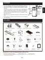
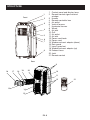
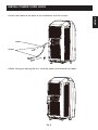
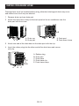
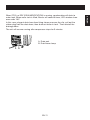

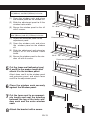
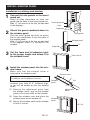


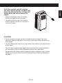
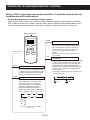
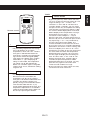
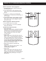

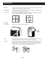
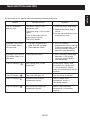


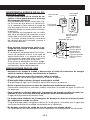


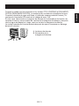

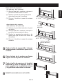
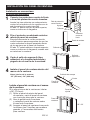


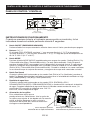

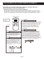

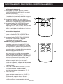
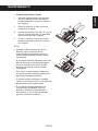
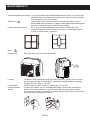
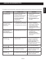


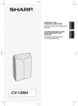
![Descargar - index [revista.cnic.edu.cu]](http://vs1.manualzilla.com/store/data/006272413_1-3e7b340a1efd00cf666ad6d77235dabf-150x150.png)