1
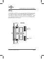
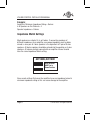
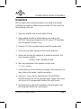
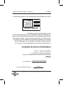
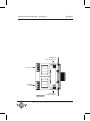
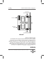
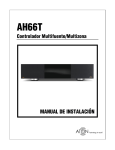
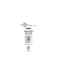
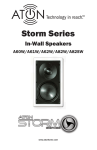
PRINT SPECS FOR ATON VOLUME CONTROL
MANUAL
INSTR, INSTL, ATON AVL100SL and AVLR100
LINEAR P/N 9901023 REV: A
INK: BLACK
MATERIAL: 60 LB WHITE COATED PAPER
PAGES: 36 PAGES
SCALE: 1-1
SIZE: 7.0 x 4.5 inches
FOLD TO 3.5 X 4.5
FOLDING: ALBUM FOLD CENTER STAPLE
NOTE: ARTWORK CREATED BY ELAN HOME
SYSTEMS
THIS MANUAL MUST BE RoHS COMPLIANT
DO NOT PRINT THIS PAGE, MANUAL STARTS ON
FOLLOWING PAGE
STEREO VOLUME CONTROLS
AVC100SL
100 Watt High Power
Stereo Sliding Volume Control
AVC100R
100 Watt High Power
Stereo Rotary Knob Volume Control
INSTALLATION MANUAL
P/N: 9901023 REV A
C
US
This ATON Volume Control is NTRL certified
to comply with local building codes.
Use Class 2 wiring and methods per
National Electrical Code NFPA70.
Install in a Listed electrical box.
VOLUME CONTROL INSTALLATION MANUAL
Contents
Introduction.....................................................2
Features.................................................................... 3
Rough-In..........................................................4
Wiring....................................................................... 5
Impedance Match Settings........................... 7-8
Installation................................................. 9-10
Operation.......................................................11
Troubleshooting.............................................12
Specifications.................................................13
Warranty........................................................14
©ATON 2010 • All rights reserved.
Page 1
VOLUME CONTROL INSTALLATION MANUAL
Introduction
The ATON AVC100SL and AVC100R High Power Stereo Volume
Control is a twelve step stereo Volume Control with variable
Impedance Match settings.
These Volume Controls are designed to connect speakers to
amplifiers with power ratings up to 100 Watts RMS. Based on
proven technology, the AVC100SL/AVC100R provide a perfect
solution when using multiple speakers in high powered multiroom applications or when basic volume functions are needed
with a receiver or amplifier.
Page 2 © ATON 2010 • All rights reserved.
VOLUME CONTROL INSTALLATION MANUAL
Features
• High Power 100 Watts RMS Per Channel
• 1X/2X/4X/8X Impedance Match
• Limited Lifetime Warranty
• Twelve Position Volume Steps
• Decora® Styling
• Screwless Wall-Plate
• ATON Quality
• PTC-Thermal Protection Circuit: When the PTC detects problems such
as, too much power, crossed speaker wiring, or improper impedance,
the circuit will open, protecting the volume control. When the problem
has been corrected, the circuit will close and resume operation.
©ATON 2010 • All rights reserved.
Page 3
VOLUME CONTROL INSTALLATION MANUAL
Rough-In
The AVC100SL/AVC100R will into the majority of single-gang boxes.
This Volume Control should not be mounted in the same rough-in box as
primary or mains volt devices, i.e. 110v, 240v--this can cause undesirable
noise in the speakers. High Wattage light dimmers can also cause noise
issues.
ALWAYS CHECK LOCAL BUILDING AND
FIRE CODES FOR LOW-VOLTAGE DEVICE
INSTALLATION AND WIRING REQUIREMENTS.
IN RETROFIT APPLICATIONS, ALWAYS CHECK FOR
OBSTRUCTIONS SUCH AS
PIPES, CONDUIT, OR ELECTRICAL WIRING BEFORE
CUTTING DRYWALL.
Page 4 © ATON 2010 • All rights reserved.
VOLUME CONTROL INSTALLATION MANUAL
Wiring
The AVC100SL / AVC100R can accommodate from 14 to 24 guage speaker
wire. Typical installations will use 16 or 18 guage stranded copper wire,
while longer runs (greater than 80 feet.) should use 14 guage wires. In-wall
runs should utilize twisted pair wiring. Please consult local building codes
before attempting in wall wire runs.
Impedance
Match Switch
AVC100SL
L+ L- AMP R- R+
L+ L- AMP R- R+
1X 2X 4X 8X
1X 2X 4X 8X
From
Amplifier
To Speakers
Impedance
Match Switch
©ATON 2010 • All rights reserved.
Page 5
VOLUME CONTROL INSTALLATION MANUAL
Impedance
Match Switch
AVC100R
L+ L- AMP R- R+
L+ L- AMP R- R+
1X 2X 4X 8X
From
Amplifier
To Speakers
8X 4X 2X 1X
Impedance
Match Switch
Page 6 © ATON 2010 • All rights reserved.
VOLUME CONTROL INSTALLATION MANUAL
Impedance Match Settings
Switch and Jumper settings on the AVC100SL and AVC100Rdetermine the
Impedance Match settings. See diagram for location of Switches and Jumpers. These setting positions depend on three things:
1. The minimum impedance rating of the amplifier used
2. The number of speakers being connected to the amplifier.
3. The nominal impedance of the speakers being utilized.
Once the above information has been determined, use the following equations to determine the correct Impedance Match setting for each specific
application. Two equations are neccessary:
Impedance Rating of Speakers
# of Speakers Connected to Amp Channel
Minimum Impedance Rating of Amp
System Impedance
8 Ohm Speaker
4 Speakers
8 Ohm Stable Amp
2 Ohm System Impedance
©ATON 2010 • All rights reserved.
= System
Impedance
= Impedance
Match Setting
= 2 Ohm System Impedance
= 4 X Setting
Page 7
VOLUME CONTROL INSTALLATION MANUAL
Example:
Amplifier's Minimum Impedance Rating = 8 ohms
# of Speakers on this Channel = 4
Speaker Impedance = 8 ohms
Impedance Match Settings
Most speakers are rated at 4, 6, or 8 ohms. If connecting speakers of
different impedances to an amplifier, an average impedance must be determined; i.e. one pair of 4 ohm speakers is the equivalent of 2 pair of 8 ohm
speakers. All 6 ohm speakers should be entered into the equation as 4 ohm
speakers. All volume controls connected to an amplifier channel should
have the same Impedance Match setting.
AVC100SL/AVC100R
8X 4X 2X 1X
Both Switches
MUST be in
Same Position
8X 4X 2X 1X
Never create settings that cause the amplifier to see an impedance below its
minimum impedance rating as this can cause damage to the amplifier.
Page 8 © ATON 2010 • All rights reserved.
VOLUME CONTROL INSTALLATION MANUAL
Installation
With the rough-in box installed and speaker wires pulled to the location,
installation can commence. Make wiring connections first, then mount the
Volume Control in the wall.
1. Disconnect amplifier from electricity before starting.
2. Secure colored faceplate to Volume Control, push knob in place
(AVC100R). Secure mounting plate to the VC, noting 'TOP' orientation,
with the supplied (2) phillips screws.
3. Strip back 1/4" of the insulation from the end of the speaker wires.
4. Twist bare wires tightly making sure their are no frayed wires.
5. Secure each wire from the amplifier to its respective connector. Use
screw terminals to tighten.
L+ to L+, L- to L-, R+ to R+, R- to R
6. Next, make connections to the speakers using the same
L +/-, R +/- scheme.
7. Carefully place the Volume Control in the rough-in box making sure not
to put strain on the speaker / amplifier connections.
8. Insert two 1" screws into the mounting holes of the AVC100SL /
AVC100R to mount the unit into the rough-in box. Tighten these screws
until the unit is at the proper depth to mount flush with the wall.
9. Place Decora cover, noting TOP orientation, at top of faceplate insert
tab. Swing down bottom and snap into place.
©ATON 2010 • All rights reserved.
Page 9
VOLUME CONTROL INSTALLATION MANUAL
10. Connect speaker wires to amplifier. Make sureproper polarity is maintained or sound quality will suffer.
11. Connect amplifier to power and test.
DO NOT CONNECT THE WIRES FROM THE VOLUME
CONTROL TO THE AMPLIFIER UNTIL THE FOLLOWING
CHECKS HAVE BEEN PEFORMED!
Checking the Installation
1. With an Ohm meter, measure the resistance between the + and - of
each pair of wires that is to be connected to the amplifier's speaker
outputs. Under no circumstances should this reading be below the
amplifier’s minimum impedance. A reading of less than 4 Ohms may
mean that the Input and Output plugs on the Volume Control have been
hooked up backwards (potentially causing damage to the amplifier). An
open reading may indicate a polarity reversal.
2. Make sure amplifier is not powered up whenmaking connections or
testing.
DO NOT REVERSE THE AMPLIFIER INPUT AND
SPEAKER OUTPUT CONNECTIONS! THIS CAN RESULT
IN DAMAGE TO EQUIPMENT AND/OR PROPERTY.
Page 10 © ATON 2010 • All rights reserved.
VOLUME CONTROL INSTALLATION MANUAL
Operation
Once the AVC100SL / AVC100R is connected to both amplifier and
speakers, adjustment and testing can occur.
1. When using a receiver or integrated amplifier with its own Volume
functions, turn the Volume all the way down.
2. Turn Volume all the way up on the AVC100SL / AVC100R, and then
slowly adjust the volume on the receiver until a comfortable listening
level is obtained.
3. Leave the receiver's Volume at that level and adjust Volume from the
AVC100SL / AVC100R.
4. When connected directly to an amplifier, follow the above procedures,
but adjust the amlifier's Gain Control rather than the Volume knob of a
receiver.
5. Once the gain has been established, no further adjustment should be
necessary.
©ATON 2010 • All rights reserved.
Page 11
VOLUME CONTROL INSTALLATION MANUAL
Troubleshooting
Symptom
Possible Cause
Solution
No audio present
1. Source not
playing
Press Play, turn ON etc.
2. Volume turned all
the way down
3. Amplifier/
Speaker connectors reversed
4. Speakers in
room miswired or
defective.
Poor audio
quality
Page 12 Increase volume
Check and correct connections
a. Test speaker at back of
amplifier
b.Verify connections
1. Clipping or
distortion
Reduce Receiver/Amplifier level
2. Speakers out of
phase
Carefully check polarity of
each speaker
3.Incorrect Impedance Match settings
See Imp. Match Section
starting on pg.8 and set
switches correctly
4. Incorrect assignment of left/right
source RCA cables or
speaker cables
Isolate to source or room
and correct
© ATON 2010 • All rights reserved.
VOLUME CONTROL INSTALLATION MANUAL
SPECIFICATIONS
AVC100SL Power Rating--Nominal................... 100 Watts RMS per Channel
AVC100R Power Rating--Nominal..................... 100 Watts RMS per Channel
Frequency Response.....................................20-20KHz +/- 0.5dB @ 8 Ohms
Total Harmonic Distortion..................................................................... < 1%
Impedance Settings.................................................................. 1X/2X/4X/8X
Minimum Speaker Load.................................................................... 4 Ohms
Dynamic Range...................................................49 dB (max to min audible)
Trim kits are included in white, almond, and ivory.
©ATON 2010 • All rights reserved.
Page 13
LIMITED LIFETIME WARRANTY
ATON (“ATON”) warrants to the original retail purchaser that the AVC100SL /
AVC100R Volume Control is free from defects in materials and workmanship,
provided that the product was purchased from an authorized ATON Home Systems
Dealer.
If the above purchaser discovers such item was not as warranted above and promptly
notifies ATON writing, ATON shall repair or replace the items at the company’s option.
This warranty shall not apply (a) to equipment not manufactured by ATON, (b) to
equipment which shall have been installed by other than an authorized ATON installer,
(c) to installed equipment which is not installed to ATON’s specifications, (d) to equipment which shall have been repaired or altered by others than ATON, (e) to equipment
which shall have been subjected to negligence, accident, or damage by circumstances
beyond ATON’s control, including, but not limited to, lightning, flood, electrical surge,
tornado, earthquake, or any other catastrophic events beyond ATON’s control, or to
improper operation, maintenance or storage, or to other than normal use of service.
With respect to equipment sold by, but not manufactured by ATON, the warranty obligations of ATON shall in all respects conform and be limited to the warranty actually
extended to ATON by its supplier. The foregoing warranties do not cover reimbursement for labor, transportation, removal, installation, or other expenses which may be
incurred in connection with repair or replacement.
Except as may be expressly provided and authorized in writing by ATON, ATON shall not
be subject to any other obligations or liabilities whatsoever with respect to equipment
manufactured by ATON or services rendered by ATON.
THE FOREGOING WARRANTIES ARE EXCLUSIVE AND IN LIEU OF ALL OTHER EXPRESSED AND IMPLIED WARRANTIES EXCEPT WARRANTIES OF TITLE, INCLUDING
BUT NOT LIMITED TO IMPLIED WARRANTIES OF MERCHANTABILITY AND FITNESS
FOR A PARTICULAR PURPOSE.
1300 EAST NEW CIRCLE DRIVE • LEXINGTON, KY 40505
ATONhome.com
GARANTÍA LIMITADA DE POR VIDA
ATON (“ATON”) garantiza al comprador minorista original que el Control
de Volumen AVC100SL / AVC100R no presenta defectos en los materiales
y mano de obra, siempre y cuando el producto se haya comprado a un
Distribuidor de Sistemas para el Hogar ATON autorizado. Si dicho comprador
descubre que el artículo no es como se garantizó arriba y avisa rápidamente
a ATON por escrito, ATON deberá reparar o cambiar los artículos, a criterio de
la compañía. Esta garantía no aplica (a) a equipos no fabricados por ATON,
(b) a equipos que hayan sido instalados por un instalador no autorizado por
ATON, (c) a equipos que no se instalaron de acuerdo con las especificaciones de ATON, (d) a equipos que hayan sido reparados o modificados por
personas ajenas a ATON, (e) a equipos que hayan sido objeto de negligencia,
accidentes o daños por circunstancias fuera del control de ATON, que
incluya, sin limitarse a ello, rayos, inundaciones, sobrecarga eléctrica,
tornados, terremotos o cualquier otra catástrofe que esté fuera del control de
ATON o debido a la utilización, mantenimiento o almacenamiento incorrectos,
o debido a causas que no sean el uso normal del servicio. Con respecto al
equipo vendido por ATON, pero fabricado por otra compañía, las obligaciones
de ATON de la garantía deben, en todo sentido, ajustarse y limitarse a la
garantía extendida realmente a ATON por su proveedor.
Las garantías precedentes no cubren reembolsos por mano de obra,
transporte, retiro, instalación u otros gastos en los que se incurra con motivo
de la reparación o sustitución.
A menos que se estipule expresamente y que ATON lo autorice por escrito,
ATON no estará sujeto en absoluto a ninguna otra obligación o responsabilidad
con respecto al equipo fabricado por ATON o servicios provistos por ATON.
LAS GARANTÍAS PRECEDENTES SON EXCLUSIVAS Y REEMPLAZAN A
CUALQUIER OTRA GARANTÍA DE TÍTULO EXPRESA E IMPLÍCITA, QUE
INCLUYA, SIN LIMITARSE A ELLO, GARANTÍAS IMPLÍCITAS DE COMERCIABILIDAD Y APTITUD PARA UN OBJETIVO EN PARTICULAR.
1300 EAST NEW CIRCLE DRIVE • LEXINGTON, KY 40505
ATONhome.com
MANUAL DE INSTALACIÓN DE CONTROL DE VOLUMEN
Especificaciones
Rango de Potencia de AVC100SL– Nominal.........100 Vatios RMS por canal
Rango de Potencia de AVC100R – Nominal..........100 Vatios RMS por canal
Respuesta de Frecuencia............................... 20-20KHz +/- 0.5dB a 8 Ohms
Distorsión armónica total...................................................................... < 1%
Configuraciones de impedancia................................................ 1X/2X/4X/8X
Carga mínima del altavoz.................................................................. 4 Ohms
Rango dinámico......................49 dB (niveles audibles máximos a mínimos)
Se incluyen elegantes juegos en blanco, almendra y marfil.
Página 14 © ATON 2010 • Todos los derechos reservados.
MANUAL DE INSTALACIÓN DE CONTROL DE VOLUMEN
1. Saturación o
distorsión
Baja calidad de
audio
Posible causa
Síntoma
Solución
Reduzca el nivel del
receptor/amplificador
Consulte la sección
Ajuste de Impedancia a
partir de la página 8 y
configure los interruptores correctamente
3.Configuraciones
incorrectas de Ajuste
de Impedancia
Controle detenidamente la
polaridad de cada altavoz
2. Los altavoces
están desfasados
4. Colocación
incorrecta de la
fuente izquierda/
derecha de los cables
RCA o cables del
altavoz
Limite el problema a la
fuente o habitación y
corríjalo
Página 13
© ATON 2010 • Todos los derechos reservados.
MANUAL DE INSTALACIÓN DE CONTROL DE VOLUMEN
Resolución de problemas
Suba el volumen
2. El volumen bajó
por completo
Pulse Reproducir, luego
ON (ENCENDIDO), etc.
1. La fuente no
se está
reproduciendo
No se oye el
audio
Posible causa
Síntoma
Página 12 Solución
a. Pruebe el altavoz
que está detrás del
amplificador
b. Verifique las
conexiones
4. Los altavoces de la
habitación tienen un
cableado incorrecto o
defectuoso.
Verifique y corrija las
conexiones
3. Los conectores del
amplificador/
altavoz están
invertidos
© ATON 2010 • Todos los derechos reservados.
MANUAL DE INSTALACIÓN DE CONTROL DE VOLUMEN
2. Asegúrese de que el amplificador no esté enchufado cuando haga las
conexiones o pruebas.
¡NO INVIERTA LAS CONEXIONES DE ENTRADA DEL
AMPLIFICADOR Y DE SALIDA DEL ALTAVOZ!
ESTO PUEDE DAÑAR EL EQUIPO Y/O LAS
INSTALACIONES.
Funcionamiento
Una vez que se conectan los dispositivos AVC100SL / AVC100R al
amplificador y los altavoces, pueden hacerse los ajustes y las pruebas.
1. Cuando use un receptor o amplificador integrado con sus propias
funciones de Volumen, baje por completo el Volumen.
2. Suba completamente el Volumen en los equipos AVC100SL / AVC100R
y, después, lentamente ajuste el volumen en el receptor hasta que
obtenga un nivel adecuado para escuchar.
3. Deje el Volumen del receptor en dicho nivel y ajuste el Volumen desde
los dispositivos AVC100SL / AVC100R.
4. Cuando la conexión se haga en forma directa a un amplificador, siga
los procedimientos mencionados anteriormente, pero ajuste el Control
de Amplificación del amplificador, en vez del botón de Volumen de un
receptor.
5. Una vez que se haya establecido la amplificación, no se necesitan hacer
otros ajustes.
© ATON 2010 • Todos los derechos reservados.
Página 11
MANUAL DE INSTALACIÓN DE CONTROL DE VOLUMEN
8. Inserte dos tornillos de 1 pulgada en los orificios de montaje de
AVC100SL / AVC100R para montar la unidad en la caja empotrada.
Ajuste estos tornillos hasta que la unidad esté en la profundidad
adecuada para montarla exactamente sobre la pared.
9. Coloque la cubierta Decora, con la orientación TOP (HACIA ARRIBA),
sobre la lengüeta de inserción de la placa frontal. Gire la base hacia
abajo e instale a presión.
10. Conecte los cables del altavoz al amplificador. Asegúrese de que se
conserve la polaridad correcta; de lo contrario, se verá afectada la
calidad del sonido.
11. Enchufe el amplificador a la corriente y pruébelo.
¡NO CONECTE LOS CABLES DEL CONTROL DE
VOLUMEN AL AMPLIFICADOR HASTA QUE SE HAYAN
REALIZADO LAS SIGUIENTES PRUEBAS!
Verificación de la instalación
1. Con un ohmímetro, mida la resistencia entre los polos + y - de cada par
de cables que se irá a conectar a las salidas del altavoz del amplificador.
El valor medido no debe estar, en ninguna circunstancia, por debajo de
la impedancia mínima del amplificador. Un valor menor que 4 Ohms
puede indicar que los enchufes de Entrada y Salida del Control de
Volumen se han conectado al revés (lo cual puede dañar,
potencialmente, al amplificador). Un valor abierto puede indicar una
inversión de polaridad.
Página 10 © ATON 2010 • Todos los derechos reservados.
MANUAL DE INSTALACIÓN DE CONTROL DE VOLUMEN
impedancia por debajo de su valor mínimo de impedancia, ya que esto
puede dañar el amplificador.
Instalación
Con la caja empotrada instalada y los cables del altavoz tendidos hasta la
ubicación, se puede dar comienzo a la instalación. Haga primero las
conexiones de cables, luego monte el Control de Volumen en la pared.
1. Desconecte el amplificador de la toma de la electricidad antes de
comenzar.
2. Fije la placa frontal de colores al Control de Volumen, presione el botón
en su lugar (AVC100R). Fije la placa de montaje al Control de Volumen
(VC, por sus siglas en inglés), con la orientación “TOP” (HACIA
ARRIBA), utilizando los (2) tornillos phillips suministrados.
3. Comenzando por el extremo de los cables del altavoz, retire de ellos 1/4
de pulgada del aislante.
4. Tuerza con fuerza los cables expuestos para garantizar que no haya
ningún cable deshilachado.
5. Fije cada cable del amplificador a su conector respectivo. Use los
terminales de los tornillos para ajustar.
L+ a L+, L- a L-, R+ a R+, R- a R
6. Luego, haga las conexiones con los altavoces usando el mismo
esquema L +/-, R +/-.
7. Con cuidado, coloque el Control de Volumen en la caja empotrada
asegurándose de no ejercer presión sobre las conexiones del altavoz/
amplificador.
© ATON 2010 • Todos los derechos reservados.
Página 9
MANUAL DE INSTALACIÓN DE CONTROL DE VOLUMEN
Altavoz de 8 Ohm
4 altavoces
= Sistema de Impedancia 2 Ohms
Amplificador estable de 8 Ohm = Configuración 4 X
Impedancia del sistema de 2 Ohm
Ejemplo:
Valor mínimo de impedancia del amplificador = 8 Ohms
Cantidad de altavoces en este canal = 4
Impedancia del altavoz = 8 Ohms
Configuraciones de ajuste de impedancia
La mayoría de los altavoces están clasificados como 4, 6 u 8 Ohms. Si
conecta altavoces de diferentes impedancias a un amplificador, se debe
determinar una impedancia promedio; por ejemplo un par de altavoces de
4 Ohms equivale a 2 pares de altavoces de 8 Ohms. Todos los altavoces de
6 Ohms deben ingresarse en la ecuación como altavoces de 4 Ohms. Todos
los controles de volumen conectados a un canal amplificador deben tener la
misma configuración de Ajuste de Impedancia.
AVC100SL/AVC100R
8X 4X 2X 1X
8X 4X 2X 1X
Ambos interruptores DEBEN
estar en la misma
posición
Jamás cree configuraciones que provoquen que un amplificador tenga una
Página 8 © ATON 2010 • Todos los derechos reservados.
MANUAL DE INSTALACIÓN DE CONTROL DE VOLUMEN
Configuraciones de ajuste de impedancia
Las configuraciones del interruptor y puente en AVC100SL y AVC100R son
determinantes para las configuraciones de ajuste de impedancia. Vea el
diagrama para observar la ubicación de los Interruptores y Puentes.
Estas posiciones de configuración dependen de tres cosas:
1. El valor mínimo de impedancia del amplificador usado.
2. La cantidad de altavoces conectados al amplificador.
3. La impedancia nominal de los altavoces utilizados.
Una vez que se haya determinado esta información, use las siguientes
ecuaciones para determinar la configuración correcta de Ajuste de
Impedancia para cada aplicación específica. Son necesarias dos ecuaciones:
Rango de impedancia de altavoces
Cantidad de altavoces conectados a un canal amplificador
Valor mínimo de impedancia de amplificadores
Impedancia del sistema
= Impedancia
del sistema
= Configuración de ajuste
de impedancia
Página 7
© ATON 2010 • Todos los derechos reservados.
MANUAL DE INSTALACIÓN DE CONTROL DE VOLUMEN
Interruptor de ajuste
de impedancia
AVC100R
L+ L- AMP R- R+
L+ L- AMP R- R+
1X 2X 4X 8X
Desde el
amplificador
a los altavoces
8X 4X 2X 1X
Interruptor de ajuste
de impedancia
Página 6 © ATON 2010 • Todos los derechos reservados.
MANUAL DE INSTALACIÓN DE CONTROL DE VOLUMEN
Cableado
Los equipos AVC100SL / AVC100R son compatibles con cables para
altavoces de calibre 14 a 24. Las instalaciones típicas usan cable de cobre
trenzado de calibre 16 ó 18, mientras que las conexiones más largas (de
más de 80 pies) deben usar cables de calibre 14. Las conexiones montadas
en la pared deben usar cables de pares cruzados. Por favor, consulte los
códigos de construcción locales antes de intentar hacer conexiones de
cables montadas en la pared.
AVC100SL
Interruptor de ajuste
de impedancia
L+ L- AMP R- R+
L+ L- AMP R- R+
1X 2X 4X 8X
1X 2X 4X 8X
Desde el
amplificador
a los altavoces
Interruptor de ajuste
de impedancia
Página 5
© ATON 2010 • Todos los derechos reservados.
MANUAL DE INSTALACIÓN DE CONTROL DE VOLUMEN
Empotrado
Los dispositivos AVC100SL/AVC100R caben en la mayoría de las cajas de
una sola entrada. Este Control de Volumen no debe montarse en la misma
caja empotrada que los dispositivos de voltios primarios o principales, por
ejemplo, 110 V, 240 V, ya que esto puede ocasionar ruido indeseable en los
altavoces. Los reguladores de luz de alto vataje también pueden ocasionar
problemas de ruidos.
SIEMPRE CONSULTE LOS CÓDIGOS DE
CONSTRUCCIÓN Y DE INCENDIOS LOCALES PARA VER
LOS REQUISITOS DE INSTALACIÓN Y CABLEADO DE
DISPOSITIVOS DE BAJO VOLTAJE.
EN APLICACIONES REACONDICIONADAS, SIEMPRE
VERIFIQUE QUE NO HAYA OBSTRUCCIONES TALES
COMO TUBERÍAS, CONDUCTOS O CABLEADO
ELÉCTRICO, ANTES DE CORTAR LA MAMPOSTERÍA.
Página 4 © ATON 2010 • Todos los derechos reservados.
MANUAL DE INSTALACIÓN DE CONTROL DE VOLUMEN
Características
• 100 Vatios RMS de alta potencia por canal
• Ajuste de impedancia: 1X/2X/4X/8X
• Garantía limitada de por vida
• Pasos para ajustar el volumen en doce posiciones
• Estilo Decora®
• Placa de pared sin tornillos
• Calidad ATON
• Circuito de protección térmica PTC: cuando el PTC detecta problemas
tales como demasiada potencia, cableado de altavoces entrecruzado o
impedancia incorrecta, se abre el circuito y, de esta manera, protege el
control de volumen. Cuando el problema se haya corregido, el circuito
se cerrará y reanudará la operación.
© ATON 2010 • Todos los derechos reservados.
Página 3
MANUAL DE INSTALACIÓN DE CONTROL DE VOLUMEN
Introducción
El Control de Volumen Estéreo de Alta Potencia ATON AVC100SL
y AVC100R es un Control de Volumen estéreo de doce pasos con
configuraciones de Ajuste de Impedancia variables.
Estos Controles de Volumen están diseñados para conectar los
altavoces a los amplificadores con rangos de potencia de hasta
100 Vatios RMS. Basados en una tecnología comprobada, los
dispositivos AVC100SL/AVC100R proveen una solución perfecta
cuando se usan altavoces múltiples en aplicaciones de alta
potencia en múltiples habitaciones o cuando se necesitan
funciones de volumen básicas con un receptor o amplificador.
Página 2 © ATON 2010 • Todos los derechos reservados.
MANUAL DE INSTALACIÓN DE CONTROL DE VOLUMEN
Contenidos
Introducción.....................................................2
Características....................................................... 3
Empotrado.......................................................4
Cableado................................................................. 5
Configuraciones de ajuste de impedancia.... 7-8
Instalación................................................. 9-10
Funcionamiento.............................................11
Resolución de problemas...............................12
Especificaciones.............................................13
Garantía.........................................................14
© ATON 2010 • Todos los derechos reservados.
Página 1
C
US
Este Control de Volumen ATON está certificado por NTRL,
en virtud de lo cual cumple con todos los códigos
de construcción locales. Use cables de Clase 1 y
métodos autorizados por el Código Eléctrico Nacional NFPA70.
Instale en una caja eléctrica enlistada.
CONTROLES DE VOLUMEN ESTÉREO
AVC100SL
Alta potencia de 100 Vatios
Control de volumen estéreo deslizante
AVC100R
Alta potencia de 100 Vatios
Control de volumen estéreo
con botón giratorio
MANUAL DE INSTALACIÓN
P/N: 9901023 REVISIÓN A