1
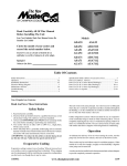
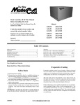
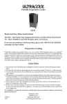
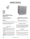
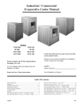
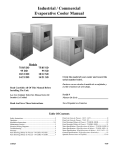
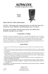
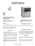
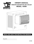
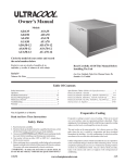
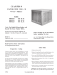
INSTALLATION & OPERATION MANUAL
SINGLE INLET EVAPORATIVE COOLERS
Circle the model of your cooler and record the serial number.
Encierrre con un circulo el modelo de su enfriador y escribe el
número de série.
Date of Purchase:
Fecha de compra:
ADA51
ASA51
AUA51
ADA5112
ASA5112
AUA5112
ADA71
ASA71
AUA71
ADA7112
ASA7112
AUA7112
Serial Number:
Número de série:
READ CAREFULLY ALL OF THIS MANUAL BEFORE INSTALLING THE UNIT
TABLE OF CONTENTS
Safety Instructions .........................................................1
How Evaporative Coolers Work.....................................1
Installation .....................................................................2
Operation .......................................................................5
Air Balancing Methods ...........................................5
Maintenance ..................................................................6
Specification Tables .......................................................7
Troubleshooting .............................................................7
Limited Warranty ...........................................................8
Tabla de Contenido En Español ..................9
Illustrated Parts List / Ilustrado
Lista de Piezas de Repuesto
(English / Español) ......................................................17
Garantía Limitada ........................................................24
READ AND SAVE THESE INSTRUCTIONS
SAFETY RULES
1. Read all instructions carefully.
2. Electrical connections should be done by a qualified electrician,
so that all electrical wiring will conform to your local codes.
3. Always turn OFF POWER and UNPLUG motor and pump inside
the cooler before installing or performing any maintenance.
4. Your cooler will run on either 120V or 240V A.C., single phase,
60 Hz (cycle) current.
5. Motor and pump have a grounded, molded plug and an automatic
thermal overload switch which will shut motor off when it
overheats. The motor will restart automatically when it cools
down.
WARNING: To reduce the risk of fire or electric shock, do not use
this fan with any “solid-state fan speed control device.”
HOW EVAPORATIVE COOLERS WORK
Evaporative cooling is nature’s way of cooling. When air is
moved over a wet surface, water is evaporated and heat is
absorbed. When stepping out of swimming pool with the
wind blowing, evaporative cooling makes you feel cool, even
though the air may be warm.
This unit works on the same principle. Air is drawn across
wet filter pads where the air is cooled by evaporation and then
circulated throughout the building. It is this combination of
cooled air and the movement of air over the skin which makes
it feel cool.
Unlike refrigeration systems which recirculate the air, an
evaporative cooler continually brings in fresh air while
exhausting old air. You are completely replacing the air every
2 to 4 minutes by opening windows or doors, by using UpDux® ceiling vents, or a combination of both. The air is always
fresh, not stale, laden with smoke and odors as happens with
refrigerated air conditioning.
PN 110498-2
REV. 3-15
INSTALLATION
CAUTIONS:
Before installing the cooler, note the following items:
•
Before installation, ensure your existing electrical system is rated for the additional amperage draw from unit.
•
Installation inside attic areas is NOT recommended.
•
If installing unit on ground, ensure surface area is level, well packed and will not erode or become unstable with water
erosion.
•
If installing on brace, or existing construction, ensure structure will hold the operating weight of the cooler. (See specification
table for operating weight.)
•
Ensure entire unit is sufficiently supported. If supporting the unit with legs at each corner, the middle of the unit where the two
sections join must be supported as well.
•
We strongly recommend consulting a professional contractor if installation will require cutting through existing structure such
as walls or roof.
•
Do not screw or drill within 5 inches of the bottom of the wet section as you could puncture the reservoir.
•
Ensure all electrical work is accomplished to local standards. An electrician may be needed for correct and safe wiring.
WARNING: Disconnect all electrical service that will be used for this unit before beginning the installation
and DO NOT reconnect until installation is complete.
PARTS AND TOOLS NEEDED:
•
•
•
•
•
•
Motor with Motor Pulley (purchased separately)
5/32 Allen Wrench (for pulley installation)
7/16 Wrench or Crescent Wrench
Phillips Screwdriver
Sill cock or water valve and tubing
Multimeter (for amp reading)
SEPARATING SECTIONS
Follow the steps below to separate the sections of the unit, if desired for ease of
installation.
1.
2.
Remove four bolts (two on each side) from the inside center post of the unit
connecting the wet section to the blower section.
On a few models, two bolts on the interior of the unit attaching the bottom
pans of the two sections will need to be removed as well.
Remove
Two Bolts
(Each Side)
Connecting
Wet And
Blower
Sections
Remove Two Bolts
Connecting Bottom Pans
Motor
Clips
MOTOR INSTALLATION
Note: Motor must be purchased separately. See Motor Specification Table for
motors that can be used.
1.
For typical 120V installation, install motor cord (provided) to motor
(purchased separately). Follow motor electrical diagram using the following
color code:
tor
Mo
Motor
Pulley
Adjustable
Motor Mount
Adjustable
Yoke
BLACK - HIGH; RED - LOW; WHITE- COMMON; GREEN - GROUND
2.
3.
When installing a 1 hp motor, reverse the adjustable yolk to accommodate
the larger motor. Adjust the cradle spacing as needed for size of motor.
Mount the blower motor onto the yokes of the motor mount. Fasten with
provided motor clips.
ALIGN PULLEYS
Motor
Leave motor cord unplugged until electrical portion of installation is
complete.
Belt
PULLEY INSTALLATION
1.
Open adjustable pulley about 5 full turns to the least diameter.
2.
Install the motor pulley onto the motor shaft so that it aligns with the blower
drive pulley and tighten with Allen wrench.
3.
Loosen adjustment screw on motor mount.
4.
Install belt onto pulleys.
5.
Rotate motor mount until belt is tight, then tighten adjustment screw to
secure belt. Check belt tension per instructions on page 5.
Note: Further adjustment to belt and pulley may be required after installation is
complete.
2
Motor
Pulley
Blower
Pulley
Adjustment Screw
110498-2
ELECTRICAL CONNECTION
WARNING: Electrical connections should be accomplished by a qualified electrician to ensure all electrical
wiring conforms to local standards.
WARNING: Follow all safety precautions when working with electrical power.
WARNING: Before proceeding with installation, ensure electrical power is disconnected until installation is
complete.
Note: This unit can be controlled with a manual 6 position switch found at a local hardware store, or with a thermostat such as
Champion’s Masterstat® Wall Control Thermostat model #110423-2. For thermostat installation refer to its operating manual.
Follow the steps below for manual switch installation:
1.
Determine location on internal wall for 6 position switch.
2.
Supply 120V or 240V power to switch, depending on motor and pump
voltages.
3.
Remove screws securing junction box to cooler cabinet.
4.
Bring four conductors plus a ground from switch to cooler junction box
(such as two 2-wire Romex® wire)
Remove Screws to Access
Wiring Connections
Junction Box
CAUTION: Make sure to use correctly sized wire and follow all
local electrical codes.
5.
Connect the four conductor wires to the leads of the motor and pump
receptacles located in the junction box. Follow the connection diagrams
below for 120V or 240V installations.
6.
Reinstall junction box to cooler cabinet.
7.
Plug motor and pump plugs into receptacles.
8.
Follow switch electrical instructions for connecting the four conductors and
power leads to switch.
Motor And Pump
Receptacles
Warning: Pump cord must be secured in retaining clip to
prevent contact with water.
120 VOLT
PUMP
MOTOR
HIGH
LOW
COMMON
GROUND
Black
Red
White
Green
Blue/Black
White
Brown
Orange
Green
Black
Red
White
Orange
Green
PUMP
HIGH
LOW
COMMON
TO SWITCH
GROUND
NOTE: If single speed
motor is used, do not
use the RED electrical
leads from the motor or
receptacle. Tape off both
RED leads.
= WIRE NUT
BLOWER MOTOR
CAUTION: Receptacles in junction box are
only for Motor and pump.
Do not plug anything
else into receptacle.
240 VOLT
PUMP
MOTOR
HIGH
LOW
COMMON
GROUND
Black
Red
Orange
Green
Blue/Black
White
Brown
Orange
Green
Black
Red
White
Orange
Green
PUMP
TO SWITCH
HIGH
LOW
COMMON
GROUND
= WIRE NUT
BLOWER MOTOR
110498-2
3
WARNING: Ensure
cooler cabinet is properly grounded to a suitable
ground connection for
maximum safety and
protection of equipment.
WATER CONNECTION
Water Shut
Off Valve
Faucet
Note: Do not connect the water supply to any soft water applications.
SILLCOCK INSTALLATION
Ferrule
A steady water supply is required for the operation of this cooler. If water
source comes from an external water faucet, a sillcock and shutoff valve
will need to be purchased and installed.
1.
Install sillcock and water valve on faucet.
2.
Run ¼” plastic or copper tubing from the faucet to the unit.
3.
Install one end of tubing to water valve by placing nut and ferrule on
tubing and tightening the nut until water tight.
Nut
Copper Or
Plastic Line
To Cooler
Sillcock With Std.
Hose Connection
FLOAT VALVE INSTALLATION (Refer to illustration)
1.
Remove items 1, 2, 3, and 4 from float.
2.
Insert float body through hole in media shield and back post panel as
shown.
3.
Install washer (1) and nut (2). Tighten to keep float from turning. Place
nut (4) and ferrule (3) on water supply line. Connect to float fitting and
tighten until water tight.
4.
Back Post
Panel
Slide float shield over float body until it snaps into place.
1
Note: After installation is complete and water is turned on, the float level will
need to be adjusted.
5.
Float
Shield
2
3
4
Float
Bend rod to adjust float. Water level should be about 1 inch below the
top opening of the overflow pipe.
OVERFLOW INSTALLATION
1.
Remove nut and place nipple through the hole in the pan with the rubber washer
between the pan and the head of the drain nipple.
2.
Screw nut onto nipple and draw up tight against bottom pan.
3.
Screw overflow pipe into nipple. This overflow pipe may be removed to drain pan
when necessary.
Overflow Pipe
Nipple
Rubber Washer
Reservoir
Note: A garden hose may be screwed onto the drain nipple to drain water away from the
unit.
Nut
SCALE BUILDUP PREVENTION
As water evaporates, minerals that were in the water will remain. Over time this
accumulation of minerals will cause scaling on the pads and in the reservoir. We
recommend the installation of either a bleed-off kit (included in unit) or a purge pump
(purchased separately) to help prevent scale build up and increase the life of the
unit. A purge pump will drain the pan every few hours of pump operation, to keep
fresh water in the unit. A bleed-off kit will continually bleed off a small portion of
water while the pump is running allowing fresh water to continually replace the old
stagnate water. Follow the instructions below for installing the bleed-off kit.
1.
Cut the pump hose and insert the barbed ends of the bleeder tee into each cut
end.
2.
Insert one end of the bleeder tubing onto the bleeder tee and run the other end
out of the cooler through the overflow pipe.
BLEED-OFF KIT
Pump Hose
Bleeder Tee
Bleed Tube
Restrictor
Overflow Pipe
Note: A restrictor clamp is provided which, if desired, may be installed onto the
bleeder tubing to restrict the amount of water being bleed off. The amount of water
to bleed off depends on the quality of the water in your area. Start with 1-2 gal/hr
and increase if needed.
AMPERAGE DRAW AND BELT TENSION
CAUTION: No attempt should be made to completely install this unit without the aid of an electrician or
someone familiar with testing amperage draw. Failure to comply with these instructions may void your
warranty.
This unit is equipped with an adjustable motor drive pulley for adjusting the blower wheel speed to the proper loading for different
duct systems. It is important that the motor drive pulley is adjusted to correct size to ensure maximum air delivery without damage
to the motor. Be sure to follow these instructions carefully.
4
110498-2
AMPERAGE DRAW AND BELT TENSION (CONT)
1.
Ensure electrical connection of unit is complete and in accordance with
all safety standards and local requirements.
2.
Reinstall inspection panels. Apply power, turn water and pump on and
allow cooler to run for a few minutes to wet pads.
3.
Check amperage and verify it conforms to amperage listed on the
specification label on motor.
•
Motor
Pulley
Motor
Decrease
Amperage
Belt
Blower
Pulley
If amperage draw is less than motor rating, turn off electrical power
and remove inspection panels. Unplug motor inside cooler, this will
protect you from someone turning on unit while you are working
inside. This should be done for your safety. Adjust pulley to a larger
diameter and readjust belt tension. Plug motor in,
install inspection panels, and retest amperage draw.
Repeat this process until correct amperage draw is
attained.
BELT TENSION
3 Lb. Pressure
3/4 Inches
Note: Increasing motor pulley diameter increases
amperage draw. Decreasing motor pulley diameter
decreases amperage draw.
CAUTION: DO NOT operate cooler with larger
amperage draw than specified on motor plate. Motor
damage will occur.
4.
Check belt tension after adjusting pulley. A 3 lb. force
should deflect the belt 3/4 inches. Readjust belt if
needed by loosening adjustment screw, rotate motor
until you have the correct belt tension, then re-tighten
screw.
Adjustment
Screw
OPERATION
NOTES: These coolers may be used without water for ventilation purposes. When outside air is cool (for example, at night)
or when humidity is high the water pump can be turned off.
To eliminate the delivery of hot air when starting the cooler, start the pump only for the first few minutes, then turn on the
blower motor.
For an evaporative cooler to be effective, there needs to be adequate exhaust. If there is not adequate exhaust, pressure and
humidity will build up in the building. You exhaust by opening doors or windows to allow the old stale air in the building to escape.
Attic exhaust dampers may also be installed to exhaust the air into the attic. The combination of attic exhaust dampers and a
thermostat can provide a completely automatic operation.
An often misunderstood concept of evaporative cooling is the amount of air that should be exhausted. How much should you open
your windows? The following two methods will help you determine the amount to open your windows.
WINDOW AREA/CFM METHOD
For proper air flow, allow an opening of at least 2 square feet (288 square inches) for each 1000 CFM rating of your unit.
Example: At 3320 CFM, model ADA 51 (1/2 hp) requires 6.6 square feet (950 square inches) of opening (3320/1000 * 2 =
6.6).
Multiply the number of windows by window width in inches and divide this into the number of square inches required for your size
unit. This will give you the height to open windows. In this example, four 36 inch wide windows should be opened 6.6 inches each.
TISSUE SUCTION METHOD
1.
Take a piece of tissue paper and cut it lengthwise into 3 equal strips.
2.
Turn your cooler on high cool.
3.
Open one window at least six inches wide in each room that you want to cool.
4.
Take the piece of tissue paper and put it up against the screen of the open window furthest from the cooler discharge
opening. Let go of it. It will do one of three things.
IF:
IF:
IF:
It falls down.
It plasters itself to the screen.
It stays on the screen lightly.
THEN: CLOSE all of the windows one inch and try step 4 again.
THEN: OPEN all of the windows one inch and try step 4 again.
THEN: PERFECT. You are done. Enjoy your cooler.
Notes:
•
When switching to low cool, you must re-balance your home. Repeat step 4.
•
Once you balance your home you can cool some areas more than others by opening those windows
more and closing the others by the same amount. Repeat step 4 to make sure your home is still air balanced.
110498-2
5
MAINTENANCE
Regular maintenance on your cooler will increase performance and extend the life of your cooler.
WARNING: Before accomplishing any maintenance ensure power is turned off and the motor and pump are
unplugged.
START OF SEASON MAINTENANCE
Accomplish these basic steps before the temperatures require cooling in case you have to acquire replacement parts.
CLEAN MEDIA
1.
With power OFF, remove inspection panels, top panels and inlet grille to access
interior of unit. Place panels in a flat, secure place to protect them from being
45°
bent or damaged.
2.
Disconnect water tube and lift off water distribution tray, accessing the media.
Air Enters
Air Exits
Remove filter pad on top.
3.
Remove and inspect media pads. Using a garden hose sprayer, wash the media
pad ensuring openings are clear of obstruction and dirt. Some light scrubbing
15°
may be required to remove mineral deposits. Do not use harsh detergents or
pressure washers in cleaning. Make every effort to keep the media intact.
4.
The original media has a standard life of 5 years, but in areas with very high
mineral content the media may have to be replaced sooner.
5.
When reinstalling existing or installing new replacement pads, ensure pads are installed in the correct configuration:
• Place the media into the unit with the steeper flute angle sloping down towards the air inlet side. This provides the most effective
water flow to the pads, allowing higher cooling efficiencies.
• We recommend using original equipment, MasterCool® media replacement pads for highest cooling capabilites.
NOTE: If competitor pads with equal angles are installed, disregard directional placement of media.
Blower Bearing
Oil Cup
OIL BEARINGS
1.
2.
3.
The blower bearings should be oiled each year with non-detergent 20/30 weight oil.
Locate and open the oil cup on each of the blower bearings and add a few drops of oil.
Add oil to motor bearings if motor has oil lines. Note: Many motors are sealed and do not
require addition of oil.
CAUTION: Do not over oil the motor, as this can cause the motor to burn out due to
excessive oil on windings.
CLEAN PUMP
1.
2.
3.
4.
5.
6.
7.
8.
9.
10.
11.
Pump should be cleaned at least once a year or more often if debris accumulates.
Unplug motor and pump from junction box, and disconnect water tube, if not already accomplished.
Using a screw driver, pry plastic retaining fastners straight up out of the pump-mounting bracket.
Slide the pump off the mounting bracket.
Extract pump from straining basket or netting and remove base of pump.
Clean pump, turn impeller to ensure free movement.
Remove pump spout and check for blockage.
Reinstall pump base and verify it is secure.
Before reinstalling pump, check water hose, bleeder line and water distributor tube to
ensure there is no blockage in any lines.
Reinstall the pump by sliding pump onto mounting bracket and reinserting the plastic
retainers to ensure pump stays in upright postion.
Reinstall water tube to the pump outlet spout.
CHECK BELT
1.
2.
Before unit is turned on, check that belt condition is good. If belt must be replaced, install
same sized belt.
Verify belt tension is correct: 3/4” deflection with 3 lbs of force.
Remove
Base
Impeller
END OF SEASON SHUTDOWN
The cooler should be prepared before any extended period of non use, and especially before winter shutdown.
1.
Drain all water from unit, supply line and pump to ensure no damage occurs from freezing. Keep water line disconnected from both
unit and supply line.
2.
Unplug motor and pump from junction box.
3.
Clean unit.
4.
Cover unit to protect finish for long periods of non use.
6
110498-2
GENERAL SPECIFICATIONS
WEIGHT (lbs)
MODELS
CABINET DIMENSIONS (in.)
DUCT OPENING (in.)
DRY
OPERATING
HEIGHT
WEIGHT
DEPTH
WIDTH
HEIGHT
51 Series
177
227
28
42
45
17-3/4
17-3/4
5112 Series
190
257
28
42
49
17-3/4
17-3/4
71 Series
213
263
34-5/8
42
48
19-3/8
19-3/4
7112 Series
233
300
34-5/8
42
52
19-3/4
19-3/4
*Includes motor weight
MOTOR SPECIFICATIONS
H.P
MOTOR PN
SPEED
VOLTS
*AMPS
110445
2
115
7.2
WEIGHT (LBS)
17
MOTOR PULLEY P/N
1/3
1/2
110447
2
115
9.8
18
110279-004
1/2
110475
2
230
4.9
15
110279-004
3/4
110449
2
115
13.8
22
110279-004
3/4
110480
2
230
16.9
21
1/2
110447
2
115
9.8
1/2
110475
2
230
71 & 7112
3/4
110449
2
Series
3/4
110480
1
1
110471
110458
MODELS
51 & 5112
Series
110279-002
MODEL
DRIVE BELT P/N
ADA51 &
ADA5112
110208 (4L-520)
110229 (4L-530) -3/4 HP
ASA51 &
ASA5112
110212 (4L-570)
110279-004
AUA51 &
AUA5112
110222 (4L-510)
18
110279-002
4.9
15
110279-002
ADA71 &
ADA7112
110230 (4L-640)
115
13.8
22
110279-004
2
230
6.9
21
110279-004
ASA71 &
ASA7112
110213 (4L-670)
2
2
115
230
16
8
29
29
110279-003
110279-003
AUA71 &
AUA7112
110213 (4L-670)
* Amperage shown is from National Electrical Code for high speed.
TROUBLESHOOTING GUIDE
PROBLEM
Failure to start or no air delivery
Inadequate air delivery with cooler running
Water draining onto roof
Musty or unpleasant odor
Motor cycles on and off
Noisy
Inadequate cooling
Excessive humidity in house
110498-2
POSSIBLE CAUSE
1.
•
•
2.
3.
•
•
•
4.
No electrical power to unit
Blown Fuse or Tripped Circuit Breaker
Electrical cord damage
Belt too loose or too tight
Motor overheated
Belt too tight
Blower bearings dry
Motor pulley diameter too large
Motor locked
REMEDY
1. Check Power
• Replace fuse or reset breaker
• Replace Cord
2. Adjust belt tension
3. Determine cause of overheating
•
Adjust pulley tension
•
Oil blower bearings
•
Adjust pulley to correct diameter
4. Replace motor
1. Insufficient air exhaust
1. Open doors or widows to increase air flow
2. Belt too loose
2. Adjust belt tension or replace if needed
3. Pads plugged/dirty
3. Clean pads
4. Motor underloaded
1. Float arm not adjusted properly
2. Overflow assembly leaking
1. Stale or stagnate water in cooler
1. Low voltage
2. Excessive belt tension
3. Blower shaft and tight or locked
4. Bearings dry
5. Motor pulley diameter too large ,
causing motor overload
1. Bearings dry
2. Wheel rubbing blower housing
3. Loose parts
1. Inadequate exhaust in house
4. Adjust pulley
1. Adjust float
2. Tighten nut and overflow pipe
1. Drain pan and clean pads
1. Check voltage
2. Adjust belt tension
3. Unplug unit and oil or replace bearings
4. Oil bearings
5. Adjust pulley so full load ampere
rating of motor is not exceeded.
1. Oil bearings
2. Unplug unit, inspect and realign
3. Tighten loose parts
1. Open windows or doors to increase air flow
2. Pads not wet
2. Check water distribution system
•
Pads clogged
•
Distribution tube holes clogged
•
Pump not working properly
1. Insufficent air exhaust
•
Clean pads
•
Clean tube holes
•
Unplug and replace or clean pump
1. Open doors or windows
7
MASTERCOOL SINGLE INLET
LIMITED WARRANTY POLICY
SALES RECEIPT REQUIRED AS PROOF OF PURCHASE FOR ALL WARRANTY CLAIMS.
This warranty is extended only to the original purchaser of this evaporative cooler when the unit is installed and used under
normal conditions against defects in workmanship and materials as follows:
•
One (1) year from date of sale on the cabinet components
•
Five (5) years on the evaporative media, which is considered a disposable component
and should be replaced periodically.
•
Two (2) years on the motor, if furnished by Champion Cooler
The manufacturer will replace the defective part/product, at its discretion. It is agreed that such replacement is the
exclusive remedy available from the manufacturer and that TO THE MAXIMUM EXTENT PERMITTED BY LAW,
THE MANUFACTURER IS NOT RESPONSIBLE FOR DAMAGES OF ANY KIND, INCLUDING INCIDENTAL AND
CONSEQUENTIAL DAMAGE OR LOSS OF PROFITS OR REVENUES.
Some states do not allow limitations on how long an implied warranty lasts, so the above limitations may not apply to you.
Exclusions from this warranty
We are not responsible for any incidental or consequential damage from any malfunction, accident, misuse, alterations,
unauthorized repairs, abuse, including failure to perform reasonable maintenance, normal wear and tear.
Alterations include the substitution of name brand components including, but not limited to media pads.
We are not responsible for any damage from the use of water softeners or treatments, chemicals or descaling materials.
We are not responsible for the cost of service calls to diagnose the cause of trouble, or labor charge to repair and/or replace
parts.
No employee, agent, dealer or other person is authorized to give any warranties or conditions on behalf of the manufacturer.
The customer shall be responsible for all labor costs incurred.
Some states do not allow the exclusion or limitation of incidental or consequential damages, so the above limitations or
exclusions may not apply to you.
How to obtain service under this warranty
Within the limitations of this warranty, purchaser with inoperative units should contact the dealer where you purchased the
cooler. If for any reason you are not satisfied with the response from the dealer, contact Customer Service at 800-643-8341
for instructions on how to obtain service within warranty as listed above.
This warranty gives the customer specific legal rights, and you may also have other rights which vary from province to
province, or state to state.
Register your product at www.championcooler.com.
8
110498-2
MANUAL DE INSTALACIÓN Y OPERACIÓN
ENFRIADOR EVAPORATIVO DE ADMISSIÓN SIMPLE
Encierrre con un circulo el modelo de su enfriador
y escribe el número de série abajo.
Fecha de Compra
ADA51
ASA51
AUA51
Número De Série
ADA5112
ASA5112
AUA5112
ADA71
ASA71
AUA71
ADA7112
ASA7112
AUA7112
LEA CON CUIDADO TODO ESTE MANUAL ANTES DE INSTALAR LA UNIDAD.
LEA Y CONSERVE ESTAS INSTRUCCIONES
TABLA DE CONTENIDO
Reglas De Seguridad ....................................................9
NORMAS DE SEGURIDAD
Cómo Funciona Los Enfriadores Evaporativos .............9
1. Lea todas las instrucciones con detenimiento.
Instalación ...................................................................10
2. Las conexiones eléctricas deben ser realizadas por un
electricista calificado, de manera que todo el cableado eléctrico
cumpla con sus normas locales.
Operación ....................................................................13
Método de Equilibrar el Aire .................................13
3. Siempre CORTE LA CORRIENTE y DESCONECTE el motor y
la bomba dentro del enfriador antes de realizar la instalación o
mantenimiento.
Mantenimiento ...........................................................14
Tablas De Especificaciones .........................................15
Lista De Piezas De Repuesto......................................17
4. Su enfriador funciona con corriente alterna de 120V o 240V,
monofásica, 60 Hz. (ciclos).
Localización de Averías
5. El motor y la bomba tienen un enchufe moldeado con descarga
a tierra y un interruptor térmico automático que apagará el
motor en caso de sobrecalentamiento. Los motores reiniciarán
de forma automática al enfriarse.
Garantía Limitada ........................................................24
ADVERTENCIA: Para reducir el riesgo de incendio o descarga
eléctrica, no utilice este ventilador con ningún “dispositivo de estado
sólido de control de velocidad de ventilador.”
CÓMO FUNCIONAN LOS
ENFRIADORES EVAPORATIVOS
El enfriamiento por evaporación es la forma natural de enfriar.
Cuando el aire se mueve sobre una superficie húmeda, el
agua se evapora y se absorbe el calor. Al salir de una piscina
mientras sopla el viento, el enfriamiento por evaporación hace
que se sienta fresco, aún cuando el aire sea cálido.
Esta unidad funciona con el mismo principio. Se hace circular
aire a través de almohadillas filtrantes húmedas donde el
aire se enfría por evaporación y luego se propaga por todo el
edificio. Es la combinación de aire enfriado y movimiento de
aire sobre su piel lo que le hace sentir fresco.
A diferencia de otros sistemas de enfriamiento que
redistribuyen el aire, el enfriador por evaporación ingresa aire
fresco de forma continua mientras expulsa el aire viciado.
Usted renueva el aire por completo cada 2 a 4 minutos al abrir
ventanas o puertas, al utilizar la ventilación de techo Up-Dux®,
o una combinación de ambas. El aire siempre está fresco, no
rancio, cargado de humo y olores como suele ocurrir con el
aire acondicionado por refrigeración.
110498-2
9
INSTALACIÓN
PRECAUCIONES:
Tome las siguientes precauciones antes de instalar su enfriador:
•
Antes de la instalación, asegúrese de que su sistema eléctrico esté preparado para el consumo adicional de voltaje de la
unidad
•
•
NO se recomienda su instalación en el ático.
De instalar la unidad sobre el suelo, asegúrese de que la zona esté nivelada, bien apisonada y que no sufrirá erosión o se
tornará inestable al ser expuesta a líquidos.
•
De instalar sobre un soporte, o una construcción existente, asegúrese de que dicha estructura soportará el peso operativo
del enfriador. (Vea la tabla de especificaciones para conocer el peso operativo.)
•
Asegúrese de que toda la unidad tenga soporte suficiente. Si apoyará la unidad sobre pies en cada esquina,
debe agregar un apoyo en el medio de la unidad, donde las dos secciones se unen.
Le recomendamos que consulte a un contratista profesional si la instalación requiere cortar estructuras existentes tales como paredes o techos.
No atornille o perfore a 5 pulgadas del fondo de la sección húmeda, ya que podría atravesar el depósito.
Asegúrese de que el trabajo eléctrico cumpla con las normas locales. Puede requerir un electricista para un
cableado correcto y seguro.
•
•
•
ADVERTENCIA: DESCONECTE TODOS LOS SERVICIOS ELÉCTRICOS QUE SE UTILIZARÁN PARA ESTA UNIDAD
ANTES DE COMENZAR LA INSTALACIÓN Y NO LOS RE-CONECTE HASTA QUE FINALICE LA INSTALACIÓN.
PIEZAS Y HERRAMIENTAS NECESARIAS:
•
•
•
•
•
•
Motor con polea para motor (se adquiere por separado)
Llave Allen 5/32 (para instalación de polea)
Llave 7/16 o Llave ajustable
Destornillador Phillips
Llave de paso o válvula de agua y tubos
Multímetro (para lectura de amperios)
SEPARACIÓN DE SECCIONES
Siga los pasos a continuación para separar las secciones de la unidad, si lo prefiere
para facilitar la instalación:
1. Quite las cuatro tuercas (dos a cada lado) del poste central interno de la unidad,
conectando la sección húmeda con la sección de la sopladora.
2. En algunos modelos, también será necesario quitar dos tuercas del interior de la
unidad, que unen los paneles del fondo de ambas secciones.
INSTALACIÓN DEL MOTOR
Quite
Los Dos
Tuercas
(A Cada
Lado) Que
Conectan
Las
Secciones
Juntas
Quite Dos Tuercas
Que Unen Los
Paneles Del Fondo
Nota: El motor se adquiere por separado. Vea la Tabla de Especificaciones de Motor
para conocer los motores que pueden utilizarse.
1.
Para una instalación típica de 120V, conecte el cable del motor (incluido) al
motor (adquirido por separado). Siga el diagrama eléctrico del motor utilizando el
siguiente código de colores:
NEGRO - ALTO; ROJO - BAJO; BLANCO - COMÚN; VERDE - TIERRA
2.
3.
Para instalar un motor de 1 CV, mueva la horquilla ajustable para hacer lugar al
motor más grande. Ajuste el tamaño del soporte según sea necesario para el
tamaño del motor. Monte el motor de la sopladora a las horquillas de la montura
del motor. Asegure el mismo con los seguros incluidos para el motor.
Seguros
r
oto
M
Polea Del
Motor
Montura
Del Motor
Ajustable
Horquilla
Ajustable
Deje el enchufe del motor desconectado hasta que la parte eléctrica de la
instalación esté completa.
ALINEAR LAS POLEAS
INSTALACIÓN DE POLEA
1.
Abra la polea ajustable unas cinco vueltas completas hasta su diámetro menor.
2.
Instale la polea del motor en el eje del motor de manera que esté alineada con la
polea de transmisión de la sopladora y ajuste con la llave Allen.
3.
Desajuste el tornillo del montura del motor.
4.
Instale la correa en las poleas.
Motor
Polea Del
Motor
Correa
Polea Del
Soplador
10
110498-2
5.
Gire la montura del motor hasta que la correa esté ajustada, y aplique el tornillo
de ajuste para asegurar la correa. Verifique la tensión de la correa según las
instrucciones de la página 13.
Nota: Puede ser necesario hacer nuevos ajustes a la correa y las poleas luego de
finalizada la instalación.
CONEXIÓN ELÉCTRICA
Tornillo Ajustable
ADVERTENCIA: Las conexiones eléctricas deben ser realizadas por un
electricista calificado para garantizar que el cableado cumpla con sus normas
locales.
ADVERTENCIA: Tome todas las precauciones de seguridad al trabajar con energía eléctrica.
ADVERTENCIA: Antes de proseguir con la instalación, asegúrese de que la energía eléctrica esté desconectada hasta
que finalice la instalación.
Nota: Se puede controlar esta unidad con un interruptor manual de 6 posiciones que se encuentra en una ferretería local, o con
un termostato tal como el Termostato de Pared de Champion, Masterstat® modelo n° 110423-2. Para la instalación del termostato
consulte el manual operativo del mismo. Siga los pasos a continuación para la instalación del interruptor manual:
1.
Determine la ubicación para el interruptor de 6 posiciones en la pared interna.
2.
Alimente el interruptor con energía de 120V o 240V, según los voltajes del motor y la bomba.
3.
Quite los tornillos que fijan la caja de conexiones a la cabina de enfriamiento.
4.
Traiga cuatro conductores más una toma de tierra desde el interruptor
hasta la caja de conexiones del enfriador (similar al cable Romex® de dos
alambres).
PRECAUCIÓN: Asegúrese de utilizar cables de tamaño adecuado y
respete las normas locales de electricidad.
5.
Conecte los cuatro cables conductores con las terminales del motor y los
receptáculos de la bomba ubicados en la caja de conexiones. Siga los
diagramas de conexión a continuación para las instalaciones de 120V y
240V.
6.
Instale nuevamente la caja de conexiones en la cabina de enfriamiento.
7.
Conecte el motor y los enchufes de la bomba en los receptáculos.
Quite los Tornillos Para
Acceder a las Conexiones
de Cableado
Caja de Conexiones
Receptáculos del
Motor y Bomba
8.
Siga las instrucciones del interruptor eléctrico para conectar los cuatro
conductores y el cable de energía al interruptor.
Advertencia: El cable de la bomba debe estar sujeto con la horquilla de
retención para evitar contacto con el agua.
120 VOLTIOS
BOMBA
ALTO
BAJO
COMÚN
TIERRA
Negro
Rojo
Blanco
Verde
Azul/Negro
Blanco
Marrón
Naranja
Verde
BOMBA
Negro
Rojo
Blanco
Naranja
Verde
ALTO
BAJO
COMÚN
A
Interruptor
TIERRA
= Empalme De Plástico
Motor Del
Ventilador
240 VOLTIOS
BOMBA
ALTO
BAJO
COMÚN
TIERRA
Negro
Rojo
Naranja
Verde
Azul/Negro
Blanco
Marrón
Naranja
Verde
Negro
Rojo
Blanco
Naranja
Verde
PRECAUCIÓN: Los
receptáculos de la caja de
conexiones son únicamente
para el motor y la bomba.
No conecte nada más al
receptáculo.
BOMBA
A
Interruptor
ALTO
BAJO
COMÚN
TIERRA
= Empalme De Plástico
Motor Del
Ventilador
110498-2
NOTA: De utilizar un
motor de velocidad única,
no utilice los cables
eléctricos ROJOS del motor
o receptáculo. Cubra con
cinta ambas terminales
ROJAS.
11
ADVERTENCIA:
Asegúrese de que el gabinete
del enfriador tenga una
conexión adecuada a tierra
para una mayor seguridad y
protección del equipo.
CONEXIÓN DE AGUA
Nota: No conecte la alimentación de agua a equipos de agua blanda.
Válvula De
Apagado
Grifo
INSTALACIÓN DE VÁLVULA DE AGUA ACOPLADA
Férula
Se requiere un suministro de agua constante para el funcionamiento del
enfriador. Si la fuente de agua viene de un grifo externo, se deberá comprar
e instalar una llave y una válvula de paso.
1.
Instale la llave de paso y la válvula de agua en el grifo.
2.
Conecte la unidad al grifo con tubos de plástico o cobre de ¼ de
pulgada.
3.
Instale un extremo de la tubería en la válvula de agua, colocando la
tuerca y el férula sobre el tubo y ajustando la tuerca hasta que sea a
prueba de agua.
Tuerca Tubo de
Plástico o
Cobre
Llave de Paso
Con Conexión de
Manguera estándar
INSTALACIÓN DE VÁLVULA DE FLOTADOR (Véase la ilustración)
1.
Quite los elementos 1, 2, 3 y 4 del flotador.
2.
Inserte el cuerpo del flotador por el orificio en el escudo medio y el panel
del poste trasero según muestra la figura.
3.
Aplique la arandela (1) y la tuerca (2). Ajuste para evitar que gire el
flotador. Coloque la tuerca (4) y el férula (3) en la línea de suministro de
agua. Conecte al conexión roscada del flotador y ajuste hasta quedar a
prueba de agua.
Protector Contra
Salpicaduras
Panel Del
Poste Trasero
1
4.
Deslice el protector contra salpicaduras del flotador sobre el cuerpo del
flotador hasta que encaje en su lugar.
Nota: Una vez que termina la instalación y se enciende el agua, será necesario
ajustar el nivel del flotador.
5.
2
3
4
Flotador
Doble la vara para ajustar el flotador. El nivel de agua debería estar a una
pulgada por debajo de la abertura del caño de desagüe.
INSTALACIÓN DE MONTAJE DE DESAGÜE
1.
Quite la tuerca y coloque la boquilla por el orificio del panel con la junta de goma entre el
panel y la cabeza de la boquilla.
2.
Atornille la tuerca a la boquilla y ajuste al panel inferior.
Caño De Desagüe
Boquilla
3.
Atornille el caño de desagüe a la boquilla. Dicho caño de desagüe puede quitarse para
drenar la fuente cuando sea necesario.
Nota: Puede atornillarse una manguera de jardín a la boquilla para drenar el agua de la unidad.
Junta De Goma
Panel Inferior
Tuerca
PREVENCIÓN DE ACUMULACIÓN DE ÓXIDO
A medida que se evapora el agua, los minerales del agua permanecen. Con
el tiempo, esta acumulación de minerales puede resultar en óxido en los
filtros y el depósito. Recomendamos la instalación de un paquete de purga
(incluido con la unidad) o una bomba de purga (adquirida por separado)
para prevenir la acumulación de óxido y aumentar la vida útil de la unidad.
Una bomba de purga drenará la fuente de forma regular para mantener
agua fresca en la unidad. Un paquete de purga hace una purga continua de
una pequeña fracción de agua mientras la bomba funciona, lo que permite
que agua fresca reemplace el agua estancada de forma continua. Siga las
instrucciones a continuación para instalar el paquete de purga.
1.
PAQUETE DE PURGA
Manguera De
La Bomba
T De Purga
Línea De Purga
Pinza De Restricción
Caño De Desagüe
Corte la manguera de la bomba e inserte los extremos dentados del T
de purga en cada punta cortada.
2.
Inserte un extremo de la línea de purga a la T de purga y lleve el otro
extremo fuera del enfriador a través del caño de desagüe.
Nota: Se incluye una pinza de restricción que puede instalarse en la línea de purga para restringir la cantidad de agua que se purga. La
cantidad de agua a purgar depende de la calidad del agua en su zona. Comience con 1-2 gal/hr. y aumente de ser necesario.
AMPERIO Y TENSIÓN DE LA CORREA
PRECAUCIÓN: No intente instalar la unidad por completo sin la ayuda de un electricista o alguien familiarizado con las
pruebas de consumo de corriente. El incumplimiento de las presentes instrucciones puede anular su garantía.
Esta unidad está equipada con una polea ajustable de transmisión del motor para ajustar la velocidad de la rueda de la sopladora
según la carga requerida para los distintos sistemas de conductos. Es importante que la polea de transmisión del motor
sea ajustada al tamaño correcto para asegurar un máximo suministro de aire sin dañar el motor. Asegúrese de seguir estas
instrucciones.
12
110498-2
1.
Asegúrese de que la conexión eléctrica de la unidad esté completa y de
conformidad con las normas de seguridad y los requisitos locales.
2.
Instale nuevamente los paneles de inspección. Active la energía, encienda
el agua y la bomba y permita que el enfriador funcione unos minutos para
humedecer los filtros.
3.
Verifique el amperio y confirme que esté de acuerdo con el amperio
detallado en la etiqueta de especificaciones del motor.
• Si el consumo de corriente es menor que el indicado por el motor, corte
la corriente eléctrica y quite los paneles de inspección. Desenchufe el
motor dentro del enfriador, eso lo protegerá si alguien enciende la unidad
mientras usted trabaja dentro de la misma. Esto debe
realizarse por su propia seguridad. Ajuste la polea a un
diámetro mayor y reajuste la tensión de la correa. Enchufe
el motor, instale los paneles de inspección y pruebe el
consumo de corriente nuevamente. Repita el proceso
hasta lograr el consumo correcto de corriente.
Nota: El incremento del diámetro de la polea del motor
aumenta el consumo de corriente. La reducción del
diámetro de la polea del motor disminuye el consumo de
corriente.
PRECAUCIÓN: NO opere el enfriador con un amperio
superior al indicado en la placa del motor. Esto dañará el
motor.
4.
Polea Del
Motor
Motor
Correa
Disminuir
Amperio
Polea Del
Soplador
TENSIÓN DE LA
CORREA
3 Libras
3/4 Pulgadas
Tornillo Ajustable
Verifique la tensión de la correa luego de ajustar la polea. Una fuerza de 3 libras debería desviar la correa unas 3/4
pulgadas. Reajuste la correa de ser necesario aflojando el tornillo de ajuste, gire el motor hasta que tenga la tensión correcta
de la correa y vuelva a apretar el tornillo.
OPERACIÓN
NOTAS: Estos enfriadores pueden utilizarse sin agua a los fines de ventilación. Cuando el aire exterior está fresco (por
ejemplo, por la noche) o cuando la humedad es alta, puede apagarse la bomba de agua.
Para detener el suministro de aire caliente al prender el enfriador, encienda solo la bomba durante los primeros minutos,
luego encienda el motor de la sopladora.
Para que el enfriador evaporativo sea efectivo, debe haber una ventilación adecuada. Si no hay un escape, la presión y humedad
se acumularán dentro del edificio. Usted facilita el escape al abrir puertas o ventanas para permitir que el aire viciado del
edificio salga al exterior. Puede instalar también rejillas regulables de ventilación en el ático para descargar el aire en el ático.
La combinación de rejillas regulables de ventilación en el ático y un termostato puede brindarle una operación completamente
automática.
Un concepto frecuentemente errado sobre el enfriamiento por evaporación es la cantidad de aire que debe liberarse. ¿Cuánto
debe abrir sus ventanas? Los dos métodos siguientes le ayudarán a determinar cuánto debe abrir sus ventanas.
MÉTODO DE CFM/SUPERFICIE DE VENTANAS
Para un flujo adecuado de aire, se necesita una abertura de al menos dos pies cuadrados (288 pulgadas cuadradas) por cada
1000 CFM de su unidad.
Ejemplo: Con 3320 CFM, el modelo ADA 51 (1/2 CV) requiere 6,6 pies cuadrados (950 pulgadas cuadradas) de abertura
(3320/1000 * 2 = 6,6).
Multiplique el número de ventanas por el ancho de las ventanas en pulgadas y divida ese número por el número de pulgadas
cuadradas necesarias según la unidad de tamaño. Esto le indicará a qué altura debe levantar las ventanas. En este ejemplo,
cuatro ventanas de 36 pulgadas de ancho deberían levantarse 6,6 pulgadas cada una.
MÉTODO DE SUCCIÓN DE PAÑUELO DE PAPEL
1.
2.
3.
4.
Tome un trozo de pañuelo de papel y córtelo a lo largo en 3 tiras iguales.
Encienda su enfriador en “High Cool” (enfriar alto).
Abra una ventana por lo menos seis pulgadas de ancho en cada habitación que desea enfriar.
Tome el trozo de papel y colóquelo contra la superficie de la ventana abierta que está más lejos de la abertura de desagüe del
enfriador. Suelte el papel. Pueden ocurrir tres cosas.
SI: Cae al suelo.
ENTONCES: CIERRE todas las ventanas por lo menos una pulgada y pruebe nuevamente el paso 4.
SI: Se pega a la superficie.
ENTONCES: ABRA todas las ventanas una pulgada y pruebe nuevamente el paso 4.
SI: Permanece ligeramente sobre la superficie.
ENTONCES: PERFECTO. Ya está todo listo. Disfrute su enfriador.
Notas:
•
Cuando cambie a “Low Cool” (enfriar bajo), debe volver a equilibrar su hogar. Repita el paso 4.
•
Una vez que equilibra su hogar puede enfriar algunas áreas más que otras abriendo más esas ventanas y cerrando las otras
en la misma proporción. Repita el paso 4 para asegurarse de que el aire de su hogar permanezca equilibrado.
110498-2
13
MANTENIMIENTO
Un mantenimiento periódico de su enfriador mejorará su rendimiento y ampliará su vida útil.
ADVERTENCIA: Antes de realizar cualquier mantenimiento, asegúrese de que la energía esté cortada y que el motor y
la bomba estén desenchufados.
INICIO DE MANTENIMIENTO ESTACIONAL
Realice los siguientes pasos básicos antes de que las temperaturas hagan necesario el enfriamiento por si necesita adquirir
piezas de repuesto.
LIMPIEZA DE MEDIO DE FILTRADO
1.
Con la energía CORTADA, quite los paneles de inspección, los paneles superiores y la parrilla de entrada para tener acceso
al interior de la unidad. Coloque los paneles sobre una superficie plana y segura, para protegerlos contra daño o dobleces.
2.
Desconecte el tubo de agua y levante la fuente de distribución de agua, para acceder al medio de filtrado. Quite la
almohadilla filtrante superior.
3.
Quite e inspeccione las almohadillas del medio de filtrado. Con un pulverizador de jardín, limpie la almohadilla del medio de
filtrado asegurándose de que las aperturas estén libres de obstrucciones y suciedad. Puede ser necesario frotar ligeramente
para quitar los depósitos minerales. No utilice detergentes fuertes o limpiadores a presión para limpiar. Intente que el medio
de filtrado quede intacto.
4.
El medio de filtrado original tiene una vida estándar de 5 años, pero
en áreas de contenido mineral muy elevado puede ser necesario
cambiar el medio de filtrado con anterioridad.
5.
Al reinstalar almohadillas existentes o al instalar almohadillas de
repuesto nuevos, asegúrese de instalar las mismos de la manera
correcta:
•
Coloque el medio de filtrado en la unidad con el ángulo de onda más
escarpado, inclinándose al lado de la entrada de aire. Esto facilita
un flujo más efectivo de agua hacia las almohadillas, lo que permite
mayor eficiencia de enfriamiento.
•
Recomendamos el uso de equipo original, las almohadillas de
repuesto de medio de filtrado MasterCool® para una mayor capacidad
de enfriamiento.
NOTA: De instalar almohadillas de la competencia con ángulos iguales,
desestime la colocación indicada del medio de filtrado.
45°
Entrada
Del Aire
Salida Del Aire
15°
Puerto de Aceite
ACEITADO DE COJINETES
1.
Los cojinetes de la sopladora deben aceitarse cada año con aceite no
detergente de grado 20/30.
2.
Ubique y abra el puerto de aceite en cada uno de los cojinetes de la
sopladora y agregue unas gotas de aceite.
3.
Añada aceite a los cojinetes del motor si el motor tiene entradas de
aceite. Nota: Muchos motores están sellados y no requieren la adición
de aceite.
PRECAUCIÓN: No coloque aceite de más en el motor, ya que
puede ocasionar que el motor se funda por exceso de aceite en los
engranajes.
LIMPIEZA DE BOMBA
1.
Se debe limpiar la bomba al menos una vez al año o más en caso de
acumulación de residuos.
2.
Desenchufe el motor y la bomba de la caja de conexiones, y desconecte
el tubo de agua, si aún permanece conectado.
3.
Con un destornillador abra las abrazaderas plásticas de retención hacia
arriba, fuera de los encajes de la montura de la bomba.
4.
Deslice la bomba hacia afuera de la montura.
5.
Quite la bomba de la red o canasta de filtro y quite la base de la bomba.
6.
Limpie la bomba, gire el rotor para asegurar que tenga movimiento libre.
7.
Quite el pico de la bomba y verifique que no tenga obstrucciones.
8.
Reinstale la base de la bomba y confirme que esté firme.
9.
Antes de reinstalar la bomba, revise la manguera de agua, la línea de
purga y el tubo de distribución de agua para asegurarse de que no haya
ninguna obstrucción en las líneas.
Quite La
Base
Hélice
14
110498-2
10.
Reinstale la bomba deslizando la misma a la guía de montura y reinsertando las abrazaderas plásticas para asegurarse de
que la bomba permanezca en posición vertical.
11.
Vuelva a conectar el tubo de agua al pico de salida de la bomba.
REVISIÓN DE CORREA
1.
Antes de encender la unidad, verifique que la correa esté en buenas condiciones. En caso de que deba reemplazarla,
instale una correa del mismo tamaño.
2.
Verifique que la tensión sea correcta: Desvío de 3/4” con 3 libras de fuerza.
APAGADO POR FINAL DE TEMPORADA
Es necesario preparar el enfriador antes de todo período prolongado fuera de uso, y en especial antes de ser apagado por el invierno.
1.
Quite toda el agua de la unidad, la línea de suministro y la bomba para asegurarse que no haya daños por congelamiento.
Mantenga la línea de agua desconectada de la unidad y del suministro de agua.
2.
Desconecte el motor y la bomba de la caja de conexiones.
3.
Limpie la unidad.
4.
Cubra la unidad para proteger el acabado durante períodos largos sin uso.
ESPECIFICACIONES GENERALES
PESO (libras)
MODELOS
DIMENSIONES DE GABINETE (PULGADAS)
ABERTURA DE DUCTO
*SECO
*LLENO
ALTURA
ANCHURA
PROFUNDIDAD
ANCHURA
ALTURA
51 Serie
177
272
28
42
45
17-3/4
17-3/4
5112 Serie
190
257
28
42
49
17-3/4
17-3/4
71 Serie
213
263
34-5/8
42
48
19-3/8
19-3/4
7112 Serie
233
300
34-5/8
42
52
19-3/4
19-3/4
* Incluye el peso del motor.
ESPECIFICACIONES DEL MOTOR
VELOCIDAD
VOLTIOS
*AMPERAJE
POLEA DEL
MOTOR NO.
C.V.
1/3
110445
2
115
7.2
17
110279-002
51 & 5112
Serie
1/2
1/2
3/4
110447
110475
110449
2
2
2
115
230
115
9.8
4.9
13.8
18
15
22
110279-004
110279-004
110279-004
3/4
110480
2
230
16.9
21
110279-004
1/2
110447
2
115
9.8
18
110279-002
1/2
110475
2
230
4.9
15
110279-002
3/4
110449
2
115
13.8
22
110279-004
3/4
110480
2
230
6.9
21
110279-004
1
110471
2
115
16
29
110279-003
1
110458
2
230
8
29
110279-003
71 & 7112
Serie
MOTOR NO
PESO
(LIBRAS)
MODELOS
* Amperaje listado es del código eléctrico nacional para la velocidad alta.
110498-2
15
MODELO
CORREA NO
ADA51 &
ADA5112
110208 (4L-520)
110229 (4L-530) -3/4 C.V.
ASA51 &
ASA5112
110212 (4L-570)
AUA51 &
AUA5112
110222 (4L-510)
ADA71 &
ADA7112
110230 (4L-640)
ASA71 &
ASA7112
110213 (4L-670)
AUA71 &
AUA7112
110213 (4L-670)
LA LOCALIZACION DE AVERIAS
PROBLEMA
CAUSA POSIBLE
1. No llega corriente
•
•
No arranca o no sale aire
Agua está drenando en el tejado
Olor a encerrado, olor desagradable
Motor se apaga y se enciende
1. Revise la corriente
Fusible fundido o Cortacircuito desactivado •
Cable eléctrico dañado
•
Cambie el fusible o restablecer el cortacircuito
Reemplace el cable
2. Correa muy floja o apretada
2. Ajuste la tensión de la correa
3. Motor recalentado
3. Determine la causa
•
•
•
Sale poco aire cuando la unidad está
funcionando
REMEDIO
Correa muy apretada
Cojinetes de la rueda están secos
Diámetro de la polea del motor demasiado
grande
•
•
•
Ajuste la tensión de la correa
Lubrique los cojinetes
Ajústela al diámetro correcto
4. Motor parado
4. Cambie el motor
1. Insuficiente abertura para que salga
el aire
1. Abra ventanas o puertas para aumentar
flujo de aire
2. Poca tensión en la correa
2. Ajuste la tensión o cambie la correa
3. Filtros obstruidos
3. Limpie los filtros
4. Motor no se carga
4. Ajuste la polea
1. El flotador no se ajusta correctamente
1. Ajuste el flotador
2. Montaje de desagüe está goteando
2. Apriete la tuerca y el tubo de desagüe
1. Agua estancado en la unidad
1. Desagüe y limpie el medio evaporativo
1. Voltaje deficiente
1. Compruebe el voltaje
2. Demasiada tensión en la correa
2. Ajuste la tensión de la correa
3. Eje del ventilador atorado
3. Lubrique o cambie los cojinetes (Desconecte la
unidad)
4. Cojinetes secos
4. Lubrique los cojinetes
5. Diámetro demasiado grande de la polea del
5. Ajústela para no exceder el grado a carga plena del
motor dando por resultado sobrecarga del motor amperio del motor
Hace Ruido
Enfriamiento inadecuado
Demasiada humedad en la casa
1. Cojinetes secos
1. Lubrique los cojinetes
2. Rueda roza contra caja de la rueda
2. Inspeccione y alinee (Desconecte la unidad)
3. Partes sueltas
3. Apriételas
1. Insuficiente abertura para que salga aire
1. Abra más las ventanas o puertas
2. El medio evaporativo no está mojado
2. Revise la distribución de agua
•
•
•
Filtros obstruidos
Agujeros del tubo obstruidos
Bomba no funciona
1. Insuficiente salida de aire
•
•
•
Limpie los filtros
Límpielos
Cámbiela o límpiela (Desconecte la unidad)
1. Abra puertas o ventanas
16
110498-2
ILLUSTRATED PARTS REPLACEMENT LIST /
LISTA ILLUSTRADA DE PIEZAS DE REPUESTO
SINGLE INLET EVAPORATIVE COOLER/
ENFRIADOR DE ENTRADA SIMPLE
Type
Models / Modelos
Pages/Paginas
Down Discharge / Descarga Descendente ...................ADA51, ADA5112, ADA71, ADA7112 ..................................18-19
Side Discharge / Descarga Lateral.......................... ASA51, ASA5112, ASA71, ASA7112 ..................................20-21
Up Discharge / Descarga Superior..........................AUA51, AUA5112, AUA71, AUA7112 ..................................22-23
When ordering parts, please be sure to furnish the following information on all orders. Failure to do so may delay your order. /
Al pedir piezas, incluya toda la información siquiente con su pedido. El no proporcionar toda esta información resultará en una
demora.
110498-2
1.
Cooler model number / El modelo de su enfriador
2.
Cooler serial number / Número de serie de la unidad
3.
Motor HP / C.V. del motor
4.
Description and part number / Descripción y número de pieza
5.
Date of purchase / Fecha de compra
17
PARTS LIST: DOWN DISCHARGE CONFIGURATION /
LISTA DE PIEZAS: CONFIGURACIÓN DE DESCARGA DESCENDENTE
No.
N°
1.
2.
3.
4.
5.
6.
7.
8.
9.
10.
11.
12.
13.
14.
15.
16.
17.
18.
19.
20.
20.
21.
22.
23.
24.
25.
26.
27.
28.
29.
30.
31.
32.
33.
34.
35.
36.
37.
38.
39.
41.
42.
43.
44.
Description / Descripción
ADA51
Top, Cabinet / Tapa De La Caja ..................................................................................... 222130-070
Top Access Panel / Panel Superior De Acceso ............................................................... 222130-074
Bottom, Blower Section / Base De La Sección De La Rueda ......................................... 322130-068
Bottom, Wet Module / Base De La Sección De Agua ..................................................... 222130-072
Front Panel / Panel Del Frente ........................................................................................ 222130-076
Inspection Panel (2 req.) / Panel De Inspección (2 req.) ................................................ 224130-002
Center Post, Right / Poste Central, Derecho .................................................................. 222130-062
Center Post, Left / Poste Central, Izquierdo.................................................................... 222130-063
Back Post, Right / Poste Trasero, Derecho ..................................................................... 222130-064
Back Post, Left / Poste Trasero, Izquierdo ...................................................................... 222130-065
Blower Housing / Caja De La Rueda .............................................................................. 324130-202
Cut-Off Plate / Placa Externa .......................................................................................... 224003-015
Blower Housing Supports (2 req.) / Soporte Para La Caja De La Rueda (2 req.)........... 218001-034
Grill / Parrilla .................................................................................................................... 222130-078
Electrical Junction Box / Caja De Empalme .................................................................... 322009-001
Motor Mount / Montura Del Motor ................................................................................... 314003-011
Motor Mount Clip Set / Conjunto De Seguros Para Montar Motor .................................. 314005-001
Motor / Motor ................................................................................................................... *
Pulley, Motor / Polea Del Motor ....................................................................................... *
Electrical Cord, Motor (115V) / Cable Eléctrico Del Motor (115V) ................................... 110372
Electrical Cord, Motor (230V) / Cable Eléctrico Del Motor (230V) .................................. §110372-2
Shaft, Blower Wheel / Eje De La Rueda ......................................................................... 110183
Blower Wheel / Rueda .................................................................................................... 16BW
Pulley, Blower Wheel / Polea De La Rueda .................................................................... 110275
Drive Belt / Correa ........................................................................................................... *
Bearings, Blower Wheel Shaft / Cojinetes Del Eje De La Rueda.................................... 110351
Receptacle, Motor / Toma De Corriente Del Motor ......................................................... 110393
Receptacle, Pump / Toma De Corriente De La Bomba ................................................... 110361
Media Shield Right / Protector Para El Medio Evaporativo, Direcho .............................. 281043-002
Media Shield Left / Protector Para El Medio Evaporativo, Izquierdo .............................. 281043-001
Water Distributor Housing / Caja Del Distribuidor De Agua ............................................ 281038-001
Water Distributor Tube / Tubo Del Distribuidor De Agua ................................................. 3D-23
Evaporative Media Set / Conjunto De Medio Evaporativo .............................................. 310117-001
Distributor Filter Pad / Filtro Del Distribuidor ................................................................... 110120
Water Reservoir / Bandeja Acumuladora De Agua ......................................................... 281041-001
Tube, Water Delivery / Tubo De Agua ............................................................................. 310716
Over Flow Assembly / Montaje De Desagüe ................................................................... 110610
Float Valve / Flotador ...................................................................................................... FL-C
Float Shield / Salpicadero Del Flotador........................................................................... 281006
Pump / Bomba ................................................................................................................ 110429
Pump Mount / Montura De La Bomba............................................................................. 218002-012
Pump Retainer / Sujetador De La Bomba ....................................................................... 110714
Anti-Flattening Coil / Espiral Protectora .......................................................................... 110847
Bleed-Off Kit / Equipo De Purga...................................................................................... 310586
ADA5112
222130-070
222130-075
322130-068
222130-073
222130-076
224130-002
222130-062
222130-063
222130-066
222130-067
324130-202
224003-015
218001-034
222130-078
322009-001
314003-011
314005-001
*
*
110372
§110372-2
110183
16BW
110275
*
110351
110393
110361
281045-002
281045-001
281033-001
3D-23
310118-001
110120
281042-001
310716
110610
FL-C
281006
110429
218002-012
110714
110847
310586
ADA71
222140-053
222130-074
322140-051
222130-072
222140-055
224140-002
222140-045
222140-046
222140-047
222140-048
324140-202
224004-003
218001-037
222140-057
322009-001
314003-012
314005-001
*
*
110372
§110372-2
110183
20BW
110276
*
110351
110393
110361
281044-002
281044-001
281038-001
3D-23
310117-002
110120
281041-001
310716
110610
FL-C
281006
110429
218002-012
110714
110847
310586
ADA7112
222140-053
222130-075
322140-051
222130-073
222140-055
224140-002
222140-045
222140-046
222140-049
222140-050
324140-202
224004-003
218001-037
222140-057
322009-001
314003-012
314005-001
*
*
110372
§110372-2
110183
20BW
110276
*
110351
110393
110361
281046-002
281046-001
281033-001
3D-23
310118-002
110120
281042-001
310716
110610
FL-C
281006
110429
218002-012
110714
110847
310586
* See the motor specification table. Motor sold separately. / Vea la tabla de especificaciones del motor. Motores se vende por separado.
§ 230V motor cord is optional and not supplied with cooler. / Cable eléctrico del motor de 230V es opcional y no se envía con el enfridor.
NOTE: Standard hardware items may be purchased from your local hardware store.
NOTA: Artículos de uso corriente pueden comprarse en la ferretería de su localidad.
18
110498-2
EXPLODED ILLUSTRATION: DOWN DISCHARGE CONFIGURATION /
ILUSTRACIÓN DE PIEZAS: CONFIGURACIÓN DE DESCARGA DESCENDENTE
110498-2
19
PARTS LIST: SIDE DISCHARGE CONFIGURATION /
LISTA DE PIEZAS: CONFIGURACIÓN DE DESCARGA LATERAL
No.
N°
1.
2.
3.
4.
5.
6.
7.
8.
9.
10.
11.
12.
13a.
13b.
14.
15.
16.
17.
18.
19.
20.
20.
21.
22.
23.
24.
25.
26.
27.
28.
29.
30.
31.
32.
33.
34.
35.
36.
37.
38.
39.
41.
42.
43.
44.
Description / Descripción
ASA51
Top, Cabinet / Tapa De La Caja ..................................................................................... 222130-070
Top Access Panel / Panel Superior De Acceso ............................................................... 222130-074
Bottom, Blower Section / Base De La Sección De La Rueda ......................................... 322130-069
Bottom, Wet Module / Base De La Sección De Agua ..................................................... 222130-072
Front Panel / Panel Del Frente ........................................................................................ 322130-077
Inspection Panel (2 req.) / Panel De Inspección (2 req.) ................................................ 224130-002
Center Post, Right / Poste Central, Derecho .................................................................. 222130-062
Center Post, Left / Poste Central, Izquierdo.................................................................... 222130-063
Back Post, Right / Poste Trasero, Derecho ..................................................................... 222130-064
Back Post, Left / Poste Trasero, Izquierdo ...................................................................... 222130-065
Blower Housing / Caja De La Rueda .............................................................................. 324130-203
Cut-Off Plate / Placa Externa .......................................................................................... 224003-015
Blower Housing Support, Right / Soporte Para La Caja De La Rueda, Derecho............ 218001-035
Blower Housing Support, Left / Soporte Para La Caja De La Rueda, Izquierdo ............. 218001-036
Grill / Parrilla .................................................................................................................... 222130-078
Electrical Junction Box / Caja De Empalme .................................................................... 322009-001
Motor Mount / Montura Del Motor ................................................................................... 314003-011
Motor Mount Clip Set / Conjunto De Seguros Para Montar Motor .................................. 314005-001
Motor / Motor ................................................................................................................... *
Pulley, Motor / Polea Del Motor ....................................................................................... *
Electrical Cord, Motor (115V) / Cable Eléctrico Del Motor (115V) ................................... 110372
Electrical Cord, Motor (230V) / Cable Eléctrico Del Motor (230V) .................................. §110372-2
Shaft, Blower Wheel / Eje De La Rueda ......................................................................... 110183
Blower Wheel / Rueda .................................................................................................... 16BW
Pulley, Blower Wheel / Polea De La Rueda .................................................................... 110275
Drive Belt / Correa ........................................................................................................... *
Bearings, Blower Wheel Shaft / Cojinetes Del Eje De La Rueda.................................... 110351
Receptacle, Motor / Toma De Corriente Del Motor ......................................................... 110393
Receptacle, Pump / Toma De Corriente De La Bomba ................................................... 110361
Media Shield, Right / Protector Para El Medio Evaporativo, Direcho ............................. 281043-002
Media Shield, Left / Protector Para El Medio Evaporativo, Izquierdo ............................. 281043-001
Water Distributor Housing / Caja Del Distribuidor De Agua ............................................ 281038-001
Water Distributor Tube / Tubo Del Distribuidor De Agua ................................................. 3D-23
Evaporative Media Set / Conjunto De Medio Evaporativo .............................................. 310117-001
Distributor Filter Pad / Filtro Del Distribuidor ................................................................... 110120
Water Reservoir / Bandeja Acumuladora De Agua ......................................................... 281041-001
Tube, Water Delivery / Tubo De Agua ............................................................................. 310716
Over Flow Assembly / Montaje De Desagüe ................................................................... 110610
Float Valve / Flotador ...................................................................................................... FL-C
Float Shield / Salpicadero Del Flotador........................................................................... 281006
Pump / Bomba ................................................................................................................ 110429
Pump Mount / Montura De La Bomba............................................................................. 218002-012
Pump Retainer / Sujetador De La Bomba ....................................................................... 110714
Anti-Flattening Coil / Espiral Protectora .......................................................................... 110847
Bleed-Off Kit / Equipo De Purga...................................................................................... 310586
ASA5112
222130-070
222130-075
322130-069
222130-073
322130-077
224130-002
222130-062
222130-063
222130-066
222130-067
324130-203
224003-015
218001-035
218001-036
222130-078
322009-001
314003-011
314005-001
*
*
110372
§110372-2
110183
16BW
110275
*
110351
110393
110361
281045-002
281045-001
281033-001
3D-23
310118-001
110120
281042-001
310716
110610
FL-C
281006
110429
218002-012
110714
110847
310586
ASA71
222140-053
222130-074
322140-052
222130-072
322140-056
224140-002
222140-045
222140-046
222140-047
222140-048
324140-203
224004-003
218001-038
218001-038
222140-057
322009-001
314003-012
314005-001
*
*
110372
§110372-2
110183
20BW
110276
*
110351
110393
110361
281044-002
281044-001
281038-001
3D-23
310117-002
110120
281041-001
310716
110610
FL-C
281006
110429
218002-012
110714
110847
310586
ASA7112
222140-053
222130-075
322140-052
222130-073
322140-056
224140-002
222140-045
222140-046
222140-049
222140-050
324140-203
224004-003
218001-038
218001-038
222140-057
322009-001
314003-012
314005-001
*
*
110372
§110372-2
110183
20BW
110276
*
110351
110393
110361
281046-002
281046-001
281033-001
3D-23
310118-002
110120
281042-001
310716
110610
FL-C
281006
110429
218002-012
110714
110847
310586
* See the motor specification table. Motor sold separately. / Vea la tabla de especificaciones del motor. Motores se vende por separado.
§ 230V motor cord is optional and not supplied with cooler. / Cable eléctrico del motor de 230V es opcional y no se envía con el enfridor.
NOTE: Standard hardware items may be purchased from your local hardware store.
NOTA: Artículos de uso corriente pueden comprarse en la ferretería de su localidad.
20
110498-2
EXPLODED ILLUSTRATION: SIDE DISCHARGE CONFIGURATION /
ILUSTRACIÓN DE PIEZAS: CONFIGURACIÓN DE DESCARGA LATERAL
110498-2
21
PARTS LIST: UP DISCHARGE CONFIGURATION /
LISTA DE PIEZAS: CONFIGURACIÓN DE DESCARGA SUPERIOR
No.
N°
1.
2.
3.
4.
5.
6.
7.
8.
9.
10.
11.
12.
13.
14.
15.
16.
17.
18.
19.
20.
20.
21.
22.
23.
24.
25.
26.
27.
28.
29.
30.
31.
32.
33.
34.
35.
36.
37.
38.
39.
41.
42.
43.
44.
Description / Descripción
AUA51
Top, Cabinet / Tapa De La Caja ..................................................................................... 322130-071
Top Access Panel / Panel Superior De Acceso ............................................................... 222130-074
Bottom, Blower Section / Base De La Sección De La Rueda ......................................... 322130-069
Bottom, Wet Module / Base De La Sección De Agua ..................................................... 222130-072
Front Panel / Panel Del Frente ........................................................................................ 222130-079
Inspection Panel (2 req.) / Panel De Inspección (2 req.) ................................................ 224130-002
Center Post, Right / Poste Central, Derecho .................................................................. 222130-062
Center Post, Left / Poste Central, Izquierdo.................................................................... 222130-063
Back Post, Right / Poste Trasero, Derecho ..................................................................... 222130-064
Back Post, Left / Poste Trasero, Izquierdo ...................................................................... 222130-065
Blower Housing / Caja De La Rueda .............................................................................. 324130-204
Cut-Off Plate / Placa Externa .......................................................................................... 224003-015
Blower Support Bracket (2 req.) / Soporte Para La Caja De La Rueda (2 req.) ............. 218123-001
Grill / Parrilla .................................................................................................................... 222130-078
Electrical Junction Box / Caja De Empalme .................................................................... 322009-001
Motor Mount / Montura Del Motor ................................................................................... 314003-011
Motor Mount Clip Set / Conjunto De Seguros Para Montar Motor .................................. 314005-001
Motor / Motor ................................................................................................................... *
Pulley, Motor / Polea Del Motor ....................................................................................... *
Electrical Cord, Motor (115V) / Cable Eléctrico Del Motor (115V) ................................... 110372
Electrical Cord, Motor (230V) / Cable Eléctrico Del Motor (230V) .................................. §110372-2
Shaft, Blower Wheel / Eje De La Rueda ......................................................................... 110183
Blower Wheel / Rueda .................................................................................................... 16BW
Pulley, Blower Wheel / Polea De La Rueda .................................................................... 110275
Drive Belt / Correa ........................................................................................................... *
Bearings, Blower Wheel Shaft / Cojinetes Del Eje De La Rueda.................................... 110351
Receptacle, Motor / Toma De Corriente Del Motor ......................................................... 110393
Receptacle, Pump / Toma De Corriente De La Bomba ................................................... 110361
Media Shield, Right / Protector Para El Medio Evaporativo, Derecho ............................ 281043-002
Media Shield, Left / Protector Para El Medio Evaporativo, Izquierdo ............................. 281043-001
Water Distributor Housing / Caja Del Distribuidor De Agua ............................................ 281038-001
Water Distributor Tube / Tubo Del Distribuidor De Agua ................................................. 3D-23
Evaporative Media Set / Conjunto De Medio Evaporativo .............................................. 310117-001
Distributor Filter Pad / Filtro Del Distribuidor ................................................................... 110120
Water Reservoir / Bandeja Acumuladora De Agua ......................................................... 281041-001
Tube, Water Delivery / Tubo De Agua ............................................................................. 310716
Over Flow Assembly / Montaje De Desagüe ................................................................... 110610
Float Valve / Flotador ...................................................................................................... FL-C
Float Shield / Salpicadero Del Flotador........................................................................... 281006
Pump / Bomba ................................................................................................................ 110429
Pump Mount / Montura De La Bomba............................................................................. 218002-012
Pump Retainer / Sujetador De La Bomba ....................................................................... 110714
Anti-Flattening Coil / Espiral Protectora .......................................................................... 110847
Bleed-Off Kit / Equipo De Purga...................................................................................... 310586
AUA5112
322130-071
222130-075
322130-069
222130-073
222130-079
224130-002
222130-062
222130-063
222130-066
222130-067
324130-204
224003-015
218123-001
222130-078
322009-001
314003-011
314005-001
*
*
110372
§110372-2
110183
16BW
110275
*
110351
110393
110361
281045-002
281045-001
281033-001
3D-23
310118-001
110120
281042-001
310716
110610
FL-C
281006
110429
218002-012
110714
110847
310586
AUA71
322140-054
222130-074
322140-052
222130-072
222140-058
224140-002
222140-045
222140-046
222140-047
222140-048
324140-204
224004-003
218001-038
222140-057
322009-001
314003-012
314005-001
*
*
110372-1
§110372-2
110183
20BW
110276
*
110351
110393
110361
281044-002
281044-001
281038-001
3D-23
310117-002
110120
281041-001
310716
110610
FL-C
281006
110429
218002-012
110714
110847
310586
AUA7112
322140-054
222130-075
322140-052
222130-073
222140-058
224140-002
222140-045
222140-046
222140-049
222140-050
324140-204
224004-003
218001-038
222140-057
322009-001
314003-012
314005-001
*
*
110372-1
§110372-2
110183
20BW
110276
*
110351
110393
110361
281046-002
281046-001
281033-001
3D-23
310118-002
110120
281042-001
310716
110610
FL-C
281006
110429
218002-012
110714
110847
310586
* See the motor specification table. Motor sold separately. / Vea la tabla de especificaciones del motor. Motores se vende por separado.
§ 230V motor cord is optional and not supplied with cooler. / Cable eléctrico del motor de 230V es opcional y no se envía con el enfridor.
NOTE: Standard hardware items may be purchased from your local hardware store.
NOTA: Artículos de uso corriente pueden comprarse en la ferretería de su localidad.
22
110498-2
EXPLODED ILLUSTRATION: UP DISCHARGE CONFIGURATION /
ILUSTRACIÓN DE PIEZAS: CONFIGURACIÓN DE DESCARGA SUPERIOR
110498-2
23
POLÍTICA DE GARANTÍA LIMITADA
PARA CUALQUIER RECLAMO RELACIONADO CON LA GARANTÍA ES NECESARIO
PRESENTAR EL RECIBO COMO PRUEBA DE COMPRA.
Esta garantía se extiende solo al comprador original de este enfriador evaporativo, siempre y cuando la unidad sea
instalada y utilizada en condiciones normales, contra defectos de fabricación y materiales como se detalla a continuación:
•
Un (1) año a partir de la fecha de la venta de los componentes del gabinete.
•
Cinco (5) años para el medio evaporativo, que se considera componente desechable y debe reemplazarse
periódicamente.
•
Dos (2) años para el motor original si es proporcionado por Champion Cooler.
El fabricante reemplazará la parte o producto defectuoso, según lo crea conveniente. Se acuerda que el reemplazo
es la única solución que el fabricante tiene disponible. ASIMISMO, HASTA EL GRADO MÁXIMO PERMITIDO POR LA
LEY, EL FABRICANTE NO SE HACE RESPONSABLE POR LOS DAÑOS DE CUALQUIER TIPO, INCLUIDOS DAÑOS
INCIDENTALES Y EMERGENTES, O LA PÉRDIDA DE GANANCIAS O INGRESOS.
Algunos estados no permiten limitaciones con respecto a cuánto tiempo dura una garantía implícita, por lo tanto es posible
que las limitaciones detalladas anteriormente no se apliquen a usted.
Exclusiones De Esta Garantía
No nos responsabilizamos por cualquier tipo de daños accidentales o resultantes, producto de cualquier tipo de mal
funcionamiento, accidente, mal uso, alteraciones, reparaciones no autorizadas, abuso, incluidos la falta de mantenimiento
razonable, uso o desgaste normal.
Las alteraciones que puede sufrir el producto incluyen la sustitución de componentes de marca, incluido, pero no limitado al
medio evaporativo.
No nos responsabilizamos por cualquier daño provocado por el uso de suavizantes o tratamientos de agua, químicos o
materiales de descalcificación.
No nos responsabilizamos por el costo de las llamadas al servicio para diagnosticar la causa del problema o el cargo de la
mano de obra para reparar o reemplazar piezas.
Los empleados, agentes, distribuidores u otras personas no se encuentran autorizados a brindar garantías o condiciones
en nombre del fabricante. El cliente será responsable por todos los costos de mano de obra incurridos.
Algunos estados no permiten la exclusión o la limitación de daños incidentales o resultantes, por lo tanto es posible que las
limitaciones o exclusiones detalladas anteriormente no se apliquen a usted.
Cómo Obtener Servicio Bajo Esta Garantía
Dentro de las limitaciones de la presente garantía, el comprador que tanga unidades fuera de funcionamiento debe
comunicarse con el concesionario donde compró el enfriador. Si por alguna razón no queda satisfecho con la respuesta
por parte del concesionario, debe comunicarse con el servicio de atención al cliente al 800-643-8341 para obtener
instrucciones sobre cómo obtener servicio dentro de la garantía, como se indica anteriormente.
Esta garantía le confiere al cliente derechos específicos. Además, el cliente puede gozar de otros derechos que varían
según la provincia o el estado.
Registre su producto en www.championcooler.com.
Champion Cooler
5800 Murray St. • Little Rock, AR 72209
www.championcooler.com
24
110498-2