1
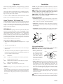
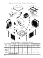
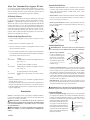
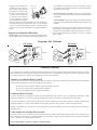
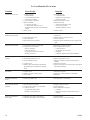
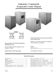
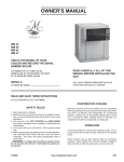
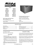
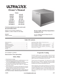
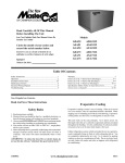
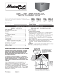
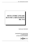
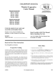
CHAMPION
EVAPORATIVE COOLER
Owner ’s Manual
Models
3000RLD
3001 RLD2
4000RLD
4001 RLD2
5000RLD
5001 RLD2
Circle The Model Of Your Cooler And
Record The Serial Number Below.
Encierre Con Un Circulo El Modelo De Su
Enfriador Y Escribe El Número De Serie Abajo.
Serial #
Read Carefully All Of This Manual
Before Installing The Unit
Lea Con Cuidado Todo Este Manual Antes
De Instalar La Unidad
Número De Serie
Read And Save These Instructions
Vea El Español En El Interior
Safety Rules
Evaporative Cooling
1. Read instructions carefully.
Evaporative cooling is nature’s way of cooling. When air is moved
over a wet surface, water is evaporated and heat is absorbed. When
stepping out of a swimming pool with the wind blowing, evaporative
cooling makes you feel cool, even though the air may be warm. The
human body itself is cooled primarily by the evaporation of
perspiration.
This unit works on the same principle. Air is drawn across wet filter
pads where the air is cooled by evaporation and then circulated
throughout the building. It is this combination of cooled air and the
movement of air over the skin which makes it feel cool.
Unlike refrigeration systems which recirculate the air, an evaporative
cooler continually brings in fresh air while exhausting old air. You are
completely replacing the air every 2 to 4 minutes by opening windows
or doors or a combination of both. The air is always fresh, not stale,
laden with smoke and odors as happens with refrigerated air
conditioning.
110524
2. Electrical hook up should be done by a qualified electrician, so that
all electrical wiring will conform to your local standards.
3. Always turn OFF POWER and UNPLUG motor and pump inside the cooler before installing or performing any maintenance.
4. Your cooler will run on either 120V or 240V A.C., single phase,
60 Hz (cycle) current.
5. Motor and pump have a grounded, molded plug and an automatic
thermal overload switch which will shut motor off when it overheats. The motor will restart automatically when it cools down.
6. Pump receptacle is for grounded evaporative cooler pump only.
Do not plug anything else into receptacle.
WARNING: To reduce the risk of fire or electric shock, do
not use this fan with any “solid-state fan speed control device.”
www.championcooler.com
3-05
Operation
Installation
For the best cooling performance, if the pads are dry, pre-wet the
pads by running the pump for a few minutes before starting the
blower.
NOTE: The pump and float are installed in the cabinet. The belt is
shipped inside the cabinet and the motor pulley kit and motor are
shipped separately.
CAUTION: Make sure that the mounting surface is strong
enough to support the operating weight of the cooler when in
use. (For operating weight, see Specification Table.)
CAUTION: Never plug in cooler until installation is complete and unit has been tested for rigidity.
These coolers may be used without water for ventilation purposes.
When outside air is cool (for example, at night) or when humidity is
high, the water pump can be turned off.
A cooler can also be installed with a thermostat and attic exhaust
dampers to provide completely automatic operation.
Open Windows To Exhaust Air
An often misunderstood concept of evaporative cooling is the amount
of air that should be exhausted. How much should you open your
windows? The fact is that most people do not open their windows
enough. The following two methods will help you determine the
amount to open your windows.
CFM Method
You should allow an opening of at least 2 square feet (288 square
inches) for each 1000 CFM rating of your unit. Example: At 3466
CFM, model 4001 RLD2 with a 1/2 Hp requires 6.9 square feet (998
square inches) of opening (3466/1000 * 2 = 6.9). Multiply the
number of windows by window width in inches and divide this into
the number of square inches required for your size unit. This will give
you the height to open windows. In this example, four 36 inch wide
windows should be opened 6.9 inches each.
Motor Installation
• Install motor cord. For typical 120V operation, connect motor
cord to motor using the following color code: Black - Hi, Red - Low,
White - Com., Green - Ground. (See Wiring Diagram).
• Mount motor. Install blower motor in the motor mount yokes,
adjusting the yoke if necessary. Fasten with the provided mounting
clips (see Fig. 1).
• Install pulley. Install the adjustable motor pulley so that it aligns
with the blower drive pulley (see Fig. 2) and tighten set screw.
Motor
Clips
Blower
Housing
Champion Air Balancing Method
1. Take a piece of tissue paper and cut it lengthwise into 3 equal
strips.
2. Turn your cooler on high cool.
Motor
Pulley
Blower
Pulley
Adjustable
Yoke
Fig. 2
Fig. 1
Electrical Installation
3. Open one window at least six inches wide in each room that you
want to cool.
WARNING: Disconnect all electrical service that will be
used for this unit before you begin the installation.
4. Take the piece of tissue paper and put it up against the screen of
the open window furthest from the cooler discharge opening. Let
go of it. It will do one of three things.
• Remove junction box.
The electrical junction
box is located in the upper inside corner of the
cooler cabinet. Remove
the two screws and slide
cover down for access to
plug wiring (Fig. 3).
IF
THEN
It falls down.
CLOSE all of the windows one inch and try step 4 again.
IF
THEN
It plasters itself to the screen.
OPEN all of the windows one inch and try step 4 again.
IF
THEN
It stays on the screen lightly.
PERFECT. You are done. Enjoy your cooler.
NOTES:
• When switching to low cool, you must rebalance your home. Repeat step 4.
• Once you balance your home you can cool some areas more than
others by opening those windows more and closing the others by
the same amount. Repeat step 4 to make sure your home is still air
balanced.
Screws
Junction Box
Fig. 3
• Hook up electrical. Electrical hook up should be done by a qualified electrician, so that all electrical wiring will conform to your
local standards. This unit is supplied with a 120V pump. For
240V pump operation, a 240V pump must be purchased. The fan
and pump receptacles will support both 120V and 240V installations. See the following wiring diagrams for 120V and 240V
installations.
IMPORTANT: When a single speed motor is used, do not use the
red lead on the receptacle and motor plug wiring. Tape off end of
both of the red leads.
WARNING: Make sure that cooler cabinet is properly
grounded to a suitable ground connection for maximum safety.
2
110524
Wiring Diagrams
120 Volts
Pump
Motor
Hi
Lo
Com.
Ground
Black
Red
White
Green
Blue/Black
White
Brown
Orange
Green
Black
Red
White
Orange
Green
Pump
To
Switch
Hi
Lo
Com.
Black
Red
Orange
Green
Pump
To
Switch
Hi
Lo
= Wire Nut
• Adjust drive pulley. After the unit is completely installed, adjust
the drive pulley to the least diameter and adjust belt tension. See
the maintenance section for adjusting belt tension.
• Check amperage. With pads wet and unit started, check amperage draw with an amperage meter.
Fig. 4
Water Connection
• Install overflow assembly. Remove nut and place nipple through
the hole in the pan, with the rubber washer between the pan and the
head of the drain nipple (Fig. 5). Screw
on nut and draw up tight against botOverflow Pipe
tom of pan. Insert overflow pipe in
nipple to retain water. Overflow pipe
Nipple
may be removed to drain pan when
Rubber Washer
Bottom Pan
necessary. A garden hose may be
Nut
screwed on the drain nipple to drain
water away from your unit.
Fig. 5
1/4” Tubing
Saddle
Valve
Cold
Water
Pipe
• Adjust pulley if necessary. If amperage draw is less than motor
rating, turn off electrical power and remove pad frame. Unplug
motor inside cooler, this will protect you from someone turning on
unit while you are working inside. This should be done for your
safety. Adjust pulley to a larger diameter and readjust belt tension, plug
motor in, install pad frame, and retest
amperage draw. Repeat this process
Decrease
until correct amperage draw is attained.
Amperage
Increasing motor pulley diameter increases amperage draw. Decreasing
motor pulley diameter decreases amFig. 9
perage draw (see Fig. 9).
CAUTION: Do not operate cooler with larger amperage
draw than specified on motor plate.
NOTE: No attempt should be made to completely install this unit
without the aid of an electrician or someone familiar with testing
amperage draw. Failure to comply with these instructions may void
your warranty.
Fig. 6
Nut
Ferrule
Water Supply
Valve
Faucet
Maintenance
WARNING: Before doing any maintenance be sure power
is off. At the time you remove a pad frame be sure to unplug
motor and pump. This is for your safety.
Spring Start-Up
Sillcock
Fig. 7
• Fill pan. Allow water to fill to within 1” of top of pan and adjust
float to maintain this water level. This can be accomplished by
bending the float rod.
110524
Fig. 8
• Start cooler. Install all pad frames, start pump, and allow to
operate until pads are wet.
Com.
Ground
Blower Motor
• Attach water line to float. Attach the water supply line to the
float in the same manner as above.
The float may be installed in either
the corner post or bracket (Fig. 8).
Float
This unit is equipped with an adjustable motor drive sheave for
adjusting the blower wheel speed to the proper loading on different
duct systems. It is important that the motor drive pulley is adjusted
to correct size to assure maximum air delivery without damage to the
motor. Be sure to follow these instructions carefully.
Blue/Black
White
Brown
Orange
Green
Black
Red
White
Orange
Green
• Connect water supply line. Find
the closest supply of water. Use a
saddle valve (Fig. 6) to connect 1/4”
tubing to the cold water supply or
use a Sillcock and water valve
connected to an outside faucet (Fig.
7). Place the nut and ferrule on the
tubing and tighten the nut until
water tight. IMPORTANT: Do
not connect the water supply to
any soft water applications. Soft
water will cause corrosion and
decrease the life of the cooler.
Bracket
Amperage Draw And Belt Tension
= Wire Nut
240 Volts
Hi
Lo
Com.
Ground
Corner
Post
Ground
Blower Motor
Pump
Motor
• Level water troughs. Operate
pump until pads are saturated.
Check each trough to see if water
is evenly dispersed in the trough.
If they are not, loosen adjustment
bolts and level trough. Retighten
bolts. Check to see that all pads
are saturated with water and that
there are no dry spots or openings in the pads.
• Oil bearings. The blower bearings and cooler motor in this unit
should be oiled with a few drops of non-detergent 20/30 weight oil
once each year. The motor does not need oil if it has no oil lines for
oiling. Motors that have no lines are lifetime oiled at the factory
and require no further oiling for the life of the unit.
CAUTION: Do not over oil. Over oiling can cause motor burn
out, due to excessive oil getting into motor winding.
3
• Replace Aspen Pads (RLD Models). The aspen pads should be
replaced once or twice a season, depending upon the length of the
season. A new clean pad is more absorbent and efficient and will
deliver substantially cooler air.
• Clean/Replace Filters (RLD2 Models). The RLD2 models have
an efficient rigid media which lasts 3-5 times longer than aspen.
Annually or more frequently depending on water conditions, these
filters will need to be cleaned. The use of a bleed off will help
decrease the buildup of deposits on the pads. To clean, remove the
filters and use a scrub brush to loosen heavy deposits. Loose dirt
and debris can be removed by shaking the dried pad. Rinse out the
bottom of the cooler and the pads and put them back into the cooler.
We recommend replacing these pads every 3 years depending on
the quality of your water. Remember, a clean pad is more absorbent
and efficient and will deliver cooler air. Note: Do Not use harsh
chemical cleaners - this will void your pad warranty.
• Check bleed-off valve to be sure
it is not clogged.
• Check belt tension. A 3 lb. force
should deflect the belt 3/4 inches (see
Fig. 10). Readjust belt if needed.
3 Lb.
3/4 Inches
blockage. After cleaning, reinstall the base onto the pump.
Reattach the pump to the mount
in the cooler using the plastic retainer to ensure that the pump
will not overturn. Do not forget
to replace the spout and water
delivery tube onto the pump
outlet. The pump has an automatic reset thermal protection.
Depress Here To
Remove
Fig. 11
Winter Shut Down
• Drain water. Always drain all of the water out of the cooler and
water supply line when not in use for prolonged periods, and particularly at the end of the season. Keep the water line disconnected
from both the unit and water supply so that it does not freeze.
• Unplug motor and pump. When cooler is not used for extended
periods, unplug the motor and pump from inside cooler.
• Cover unit. To protect the life of the finish, a cover for the unit is
suggested in extended periods of non use.
Fig. 10
• Clean pump. Cleaning the pump is necessary once a year at startup. For your safety, turn unit off and unplug motor and pump.
Remove the pump from the mount slot. Remove the base of the
pump as shown in Fig. 11. Clean the pump and turn the impeller to
ensure free operation. Remove the pump spout and check for any
By following the operating, installation, and maintenance suggestions
as outlined, you can get many years of efficient and satisfactory
service from your cooler. In the event additional information is desired, your dealer will be more than glad to assist you in every possible
way.
Limited Warranty
This warranty is extended to the original purchaser of an evaporative cooler installed and used under normal conditions. It does not cover
damages incurred through accident, neglect, or abuse by the owner. We do not authorize any person or representative to assume for us any
other or different liability in connection with this product.
Terms And Conditions Of Warranty
From the date of purchase, if any original component part provided by Champion Cooler fails due to defect in material or factory
workmanship only, we will provide the replacement part as follows:
Eight Years on the original base assembly if water leakage should occur due to rust out.
Two years on the rigid evaporative media (RLD2 models only).
One Year on all other original component parts.
Exclusions From The Warranty
We are not responsible for replacement of cooler pads on RLD units. These are disposable components and should be replaced periodically.
We are not responsible for any incidental or consequential damage resulting from any malfunction.
We are not responsible for any damage received from the use of water softeners, chemicals, descale material, plastic wrap, or if a motor of
a higher horsepower than what is shown on the serial plate is used in the unit.
We are not responsible for the cost of service calls to diagnose cause of trouble, or labor charge to repair and/or replace parts.
How To Obtain Service Under This Warranty
Contact the Dealer where you purchased the evaporative cooler. If for any reason you are not satisfied with the response from the dealer,
contact the Customer Service Department: Champion Cooler, 5800 Murray Street, Little Rock, Arkansas 72209. 1-800-643-8341. E-mail:
[email protected]
This limited warranty applies to original purchaser only.
4
110524
Troubleshooting
Problem
Possible Cause
Remedy
Failure to start or no air
delivery
1. No electrical power to unit
• Fuse blown
• Circuit breaker tripped
• Electric cord unplugged or damaged
2. Belt too loose or tight
3. Motor overheated
• Belt too tight
• Blower bearings dry
• Motor pulley diameter too large
4. Motor locked
1. Check power
• Replace fuse
• Reset breaker
• Plug in cords or replace if damaged
2. Adjust belt tension
3. Determine cause of overheating
• Adjust belt tension
• Oil blower bearings
• Adjust pulley to correct diameter
4. Replace motor
Inadequate air delivery
with cooler running
1.
2.
3.
4.
1.
2.
3.
4.
Inadequate cooling
1. Inadequate exhaust in house
2. Pads not wet
• Pads plugged
• Open spots in pads
• Trough holes clogged
• Pump not working properly
1. Open windows or doors to increase air flow
2. Check water distribution system
• Replace pads
• Repack pads
• Clean trough and unplug holes
• Replace or clean pump (Unplug unit)
Motor cycles on and off
1.
2.
3.
4.
5.
1.
2.
3.
4.
5.
Noisy
1. Bearings dry
2. Wheel rubbing blower housing
3. Loose parts
1. Oil bearings
2. Inspect and realign (Unplug unit)
3. Tighten loose parts
Excessive humidity in
house
1. Inadequate exhaust
1. Open doors or windows
Musty or unpleasant
odor
1. Stale or stagnate water in cooler
2. Pads mildewed or clogged
3. Pads not wetting properly
• Trough holes clogged
• Pump not working properly
1. Drain pan and clean pads
2. Replace pads
3. Check water distribution system
• Clean
• Replace or clean pump (Unplug unit)
Water draining onto roof
1. Float arm not adjusted properly
2. Overflow assembly leaking
1. Adjust float
2. Tighten nut and overflow pipe.
110524
Insufficient air exhaust
Belt too loose
Pads plugged
Motor underloaded
Low voltage
Excessive belt tension
Blower shaft tight or locked
Bearings dry
Motor pulley diameter too large causing motor overload
Open windows or doors to increase air flow
Adjust belt tension or replace if needed
Replace pads
Adjust pulley to full load ampere rating of motor
Check voltage
Adjust belt tension
Oil or replace bearings (Unplug unit)
Oil bearings
Adjust pulley so full load ampere rating of motor is
not exceeded
5
Replacement Parts List / Lista De Piezas De Repuesto
When ordering parts, please be sure to furnish the following information on all orders. Failure to do so may delay your order. /
Al pedir piezas, incluya toda la información siquiente con su pedido. El no proporcionar toda esta información resultará en una demora.
1.
2.
3.
4.
5.
No.
N°
1.
2.
3.
4.
5.
5A.
5B.
6.
6A.
7.
8.
9.
10.
11.
12.
13.
14.
15.
16.
17.
18.
19.
20.
20.
21.
22.
23.
24.
25.
26.
27.
28.
30.
31.
32.
34.
35.
36.
37.
38.
39.
40.
41.
42.
Cooler model number / El modelo de su enfriador
Cooler serial number / Número de serie de la unidad
Motor HP / C.V. del motor
Description and part number / Descripción y número de pieza
Date of purchase / Fecha de compra
3000 RLD
Description / Descripción
3001 RLD2
Top Pan / Tapa Superior --------------------------------------------------------------------- 220901-002
Bottom Pan / Base De La Caja -------------------------------------------------------------- 320905-002
Louvered Side / Lado Con Rejillas De Ventilación ---------------------------------------- 224007-004
Water Trough / Canal De Agua -------------------------------------------------------------- 226003-002
Aspen Pads (RLD) / Filtros De Paja (RLD) ----------------------------------------------- 110094
Glass Fiber Pad (RLD) / Filtros De Vidrio (RLD) ---------------------------------------- 110129
Pad Set (RLD2) / Conjunto De Filtros (RLD2) -------------------------------------------- 110100
Pad Retainers (RLD) / Soporte Para Los Filtros (RLD) --------------------------------- 3PW-5
Pad Retainers (RLD2) / Soporte Para Los Filtros (RLD2) ------------------------------ 3PW-12
Corner Post, With Float Hole / Poste De Esquina, Con Agujero Para Flotador ----- 224003-012
Corner Post, No Float Hole / Poste De Esquina, Sin Agujero Para Flotador --------- 224003-030
Cut-Off Plate / Placa Externa ---------------------------------------------------------------- 224002-001
Blower Housing / Caja De La Rueda ------------------------------------------------------- 324106-302
Blower Wheel / Rueda ------------------------------------------------------------------------ 12BW
Shaft, Blower Wheel / Eje De La Rueda ---------------------------------------------------- 110182
Bearings, Blower Wheel Shaft / Cojinetes Del Eje De La Rueda ------------------------ 110351
Pulley, Blower Wheel / Polea De La Rueda ------------------------------------------------ 110274
Drive Belt / Correa De Transmisión -------------------------------------------------------- 110211
Motor / Motor --------------------------------------------------------------------------------- *
Pulley, Motor / Polea Del Motor ------------------------------------------------------------ *
Motor Mount / Montura Del Motor -------------------------------------------------------- 314003-002
Motor Mount Clips / Seguros Para Montar Motor -------------------------------------- 314005-001
Electrical Cord, Motor (115V) / Cable Eléctrico Del Motor (115V) -------------------- 110372
Electrical Cord, Motor (230V) / Cable Eléctrico Del Motor (230V) -------------------- 110372-2
Float Valve / Válvula De Flotador ----------------------------------------------------------- FL-BK
Pump Mount / Montura De La Bomba ---------------------------------------------------- 216003-001
Pump Screen / Malla Para La Bomba ------------------------------------------------------ 281001-001
Pump Assembly / Bomba -------------------------------------------------------------------- C60P-120
Pump Retainer / Sujetador De La Bomba -------------------------------------------------- 110866N
Connector, Pump Mount / Unión Para La Montura De La Bomba ------------------- 3PM-1
Float Bracket / Soporte Del Flotador ------------------------------------------------------- 216001-003
Tube, Water Delivery / Tubo De Agua ------------------------------------------------------ 310716
Over Flow Assembly / Montaje De Desagüe ---------------------------------------------- 3OA-1
Water Distributor Assembly / Sistema Del Distribuidor De Agua ---------------------- 3D-5
Holder, Water Distributor / Soporte Para El Distribuidor De Agua -------------------- 110574
Electrical Junction Box / Caja De Empalme ----------------------------------------------- 320106-002
Receptacle, Motor / Tomacorriente Del Motor -------------------------------------------- 110393
Receptacle, Pump / Tomacorriente De La Bomba ---------------------------------------- 110361
Bearing Mount, Right / Montura Del Cojinete, Direcha --------------------------------- Bearing Mount, Left / Montura Del Cojinete, Izquierda --------------------------------- Motor Mount Support, Right / Soporte Para El Montura Del Motor, Direcho ------ Motor Mount Support, Left / Soporte Para El Montura Del Motor, Izquierdo ------ Channel Retainer Support / Soporte Para El Retendedor De Canal -------------------- Bleed-Off Kit / Equipo De La Válvula De Desahogo ------------------------------------ 310586
4000 RLD
4001 RLD2
220903-002
320906-002
224008-004
226003-003
110093
110129-001
110101
3PW-6
3PW-13
224003-013
224003-029
224004-002
324110-001
16BW
110183
110351
110275
110212
*
*
314003-004
314005-001
110372
110372-2
FL-BK
216003-001
281001-001
C60P-120
110866N
3PM-1
216001-003
310716
3OA-1
3D-6
110574
320106-002
110393
110361
310586
5000 RLD
5001 RLD2
220905-005
320908-003
224111-004
226003-004
110095
110129-002
110102
3PW-7
3PW-14
224003-014
224003-031
224004-003
324111-101
20BW
110183
110351
110276
110213
*
*
314003-009
314005-001
110372
110372-2
FL-BK
216003-001
281001-001
C60P-120
110866N
3PM-1
216001-003
310716
3OA-1
3D-7
110574
320107-002
110393
110361
214111-006
214111-001
214111-004
214111-005
218111-001
310586
* See motor specification table. / Vea la tabla de especificaciones del motor.
NOTE: Standard hardware items may be purchased from your local hardware store.
NOTA: Artículos de uso corriente pueden comprarse en la ferretería de su localidad.
6
110524
Replacement Parts Drawing / Dibujo De Piezas De Repuesto
1
41
40
31
32
18
39
41
19
11
36
20
38
35
34
37
16
17
5000RLD & 5001RLD2
18
15
3
4
12
8
13
3
14
28
27
10
6 (RLD)
5A (RLD)
6A
(RLD2)
26
25
22
5B
(RLD2)
9
24
30
5 (RLD)
8
21
7
23
2
3
42
3
General Specifications / Especificaciones Generales
Model No.
Modelo
HP
C.V.
3000 RLD
3001 RLD2
1/3
1/2
1/3
1/2
3/4
1/2
3/4
1
4000 RLD
4001 RLD2
5000 RLD
5001 RLD2
Weight (lbs.)
Peso (libras)
*Dry
Seco
*Operating
Lleno
139
140
174
175
179
224
228
235
206
207
257
258
262
316
320
327
Cabinet Dimensions (in.)
Dimensiones De La Caja (pulgadas)
Duct Opening (in.)
Abertura De Ducto (pulgadas)
Height
Altura
Width
Anchura
Depth
Profundidad
Width
Anchura
Height
Altura
29 3/16
34 1/8
34 1/8
13 5/8
13 5/8
30 11/16
39
39
17 3/4
17 3/4
37 11/16
41 1/4
41 1/4
19 3/4
19 3/4
* Motor weight is included. / Incluye el peso del motor.
110524
7
Motor Specifications / Especificaciones Del Motor
Model No.
Modelo
3000 RLD
3001 RLD2
HP
HP
Motor Part #
Motor - N°
Speed
Velocidad
Volts
Voltios
Amps*
Amperaje
Motor Pulley Part #
Polea Del Motor - N°
1/3
110445
2
2
115
7.2
110277
115
9.8
1/2
1/3
4000 RLD
4001 RLD2
1/2
3/4
1/2
5000 RLD
5001 RLD2
3/4
1
110447
110475
2
230
4.9
110445
2
115
7.2
110447
2
115
9.8
110475
2
230
4.9
110449
2
115
13.8
110480
2
230
6.9
110447
2
115
9.8
110447
2
230
4.9
110449
2
115
13.8
110480
2
230
6.9
110471
2
115
16
110458
2
230
8
110278
Drive Belt Part #
Banda - N°
110211 (4L-450)
110277
110278
110212 (4L-570)
110279-001
110277
110278
110213 (4L-670)
110279
* Amperage shown is from National Electrical Code for high speed. / Amperaje listado es del código eléctrico nacional para la alta velocidad.
Lea y Conserve Estas Instrucciones
Reglas De Seguridad
1. Lea las instrucciones con cuidado.
2. Las conexiones eléctricas deben ser hechas por un electricista competente, para que todo el cableado eléctrico cumpla con los requisitos
establecidos en su localidad.
3. Siempre CORTE LA CORRIENTE y DESCONECTE el motor
y la bomba en el interior del aparato antes de instalar o realizar
cualquier labor de mantenimiento.
4. Su enfriador funciona con corriente alterna de 120V o 240V, de una
fase y 60 Hz. (ciclos).
5. El motor y la bomba están provistos de clavijas moldeadas, con
toma de tierra, y se apagarán automáticamente en caso de sobrecalentamiento. Los motores volverán a funcionar cuando se enfrían.
ADVERTENCIA: Para reducir el riesgo de incendio o toques eléctricos, no use este ventilador con ningún “dispositivo
de estado sólido para controlar la velocidad del ventilador.”
Enfriamiento Por Evaporación
El enfriamiento por medio de evaporación es la manera de la naturaleza de refrescarse. Cuando el aire se mueve sobre una superficie
mojada, se evapora el agua y se absorbe el calor. Al salir de una piscina
con el viento que sopla usted se siente fresco, aunque el aire puede ser
caliente. El cuerpo humano sí mismo es refrescado principalmente
por la evaporación del sudor.
8
Este enfriador funciona usando el mismo principio. El aire se traza a
través de los filtros mojados donde el aire se enfría por medio de
evaporación y después circula a través del edificio. Se hace frío de la
sensación cuando tiene esta combinación del aire enfriado y del movimiento del aire sobre la piel.
A diferencia de los acondicionadores de aire que recirculan el aire, un
enfriador evaporativo trae continuamente por dentro el aire fresco
mientras agota el aire viejo. Se reemplaza completamente el aire cada
2 a 4 minutos, abriendo las ventanas o las puertas o una combinación
de ambas. El aire es siempre fresco, no es viciado, cargado de humo y
olores como ocurre con los sistemas de aire acondicionado a base de
refrigeración.
Funcionamiento
Para el mejor funcionamiento, si los filtros son secos, prenda sólo la
bomba durante unos cuantos minutos antes de prender el motor del
ventilador.
Su unidad puede ser utilizada sin agua para proporcionar ventilación
solamente. Cuando hace fresco (por ejemplo, de noche) o cuando la
humedad es alta, la bomba de agua puede ser apagada.
La unidad puede ser instalada también con termostato y reguladores
de escape en el ático para obtener un funcionamiento totalmente
automático.
110524
Abre Las Ventanas Para Agotar El Aire
Instalación Del Motor
Un concepto a menudo entendido mal de enfriamiento por evaporación es la cantidad de aire que debe ser agotada. Cuánto debe usted
abrir sus ventanas? El hecho es que la mayoría de la gente no abre sus
ventanas bastante. Los dos métodos siguientes le ayudarán.
• Instale el cable del motor. Para la instalación típica de 120V,
conecte el cable al motor usando las claves de colores siguientes:
Negro - Alto, Rojo - Bajo, Blanco - Común, Verde - Tierra. (Vea la
esquema del cableado).
El Metodo Primero
• Monte el motor. Instale el motor del ventilador en las horquillas de
la montura. Ajuste la horquilla ajustable si es necesario y sujete el
motor con los seguros (véase fig. 1).
Usted debe dejar una abertura de dos pies cuadrados por cada 1000
P.C.M. (pies cúbicos por minuto), según la capacidad de su modelo.
Ejemplo: Un Modelo 4001 RLD2 con un motor de 1/2 C.V y de
3466 P.C.M. requiere 6,9 pies cuadrados (998 pulgadas cuadradas) de
abertura (3466/1000 * 2 = 6,9). Ahora, multiplique el número de las
ventanas por el ancho de las mismas; luego divida esta cantidad entre
el número de pulgadas cuadradas requeridas para su unidad. El resultado le dice hasta qué altura hay que abrir las ventanas. En este
ejemplo, cuatro ventanas que miden 36 pulgadas (0,9 m.) de ancha se
deben abrir 6,9 pulgadas por cada una.
• Instale la polea del motor. Instale la polea ajustable del motor
para que queda alineada con la polea del ventilador (véase fig. 2) y
apriete el tornillo.
Seguros
Polea Del
Motor
Caja De
La Rueda
El Metodo De Equilibrar El Aire
1. Tome un pedazo de papel de seda y córtelo a lo largo en 3 tiras
iguales.
2. Ponga en marcha a su enfriador a “High-Cool”.
3. Abra una ventana por lo menos seis pulgadas de ancho en cada
sitio que usted desee refrescar.
4. Tome un pedazo de papel de seda y póngalo contra la pantalla de
la ventana abierta más lejos de la apertura del enfriador. Suéltalo al
papel de seda. Hará una de tres cosas:
SI:
ENTONCES:
Se caiga.
CIERRE todas las ventanas una pulgada e intente el
paso 4 otra vez.
SI:
ENTONCES:
Se queda contra la pantalla con fuerza.
ABRA todas las ventanas una pulgada e intente el
paso 4 otra vez.
SI:
ENTONCES:
Se queda ligeramente contra la pantalla.
PERFECTO. Se ha acabado. Goce del aire refrescante.
NOTAS:
• Al poner el enfriador a “low-cool”, usted debe reequilibrar el aire de
su hogar. Repita el paso 4.
• Al equilibrar el aire de su hogar usted puede refrescar algunas áreas
más que otras abriendo esas ventanas más y cerrando las otras por
la misma cantidad. Repita el paso 4. Asegurarse de que el aire de su
hogar sea equilibrado.
Instalación
NOTA: Los enfriadores vienen con la bomba y el flotador instalados.
La correa está incluida en la unidad y el motor y el equipo de la polea
del motor se envían por separados.
PRECAUCION: La superficie en que ha de colocarse el
enfriador deberá aguantar el peso completo de la unidad cuando
ésta está en funcionamiento. (Para saber este peso, vea la tabla
de especificaciones.)
PRECAUCION: No conecte el enfriador hasta que la instalación esté completa y se haya comprobado la estabilidad del
mismo.
110524
Polea Del
Ventilador
Horquilla
Ajustable
Fig. 2
Fig. 1
Instalación Eléctrica
ADVERTENCIA: Desconecte todos los servicios eléctricos
que serán usados en esta unidad antes de instalar el enfriador.
• Quite la caja de empalme.
La caja de empalme se encuentra en el rincón superior
del interior del enfriador.
Quite los dos tornillos de la
caja y deslice la caja hacia abajo para tener acceso al
cableado (fig. 3).
Tornillos
Caja De
Empalme
Fig. 3
• Conecte el cableado eléctrico. Las conexiones eléctricas deben
ser hechas por un electricista competente, para que todo el cableado
eléctrico cumpla con los requisitos establecidos por su localidad.
Esta unidad viene equipado con una bomba de 120V. Para la alimentación de 240V, necesita comprar una bomba de 240V. Las tomas de
corriente del ventilador y bomba soportan ambas instalaciones de
120V y 240V. Vea las esquemas del cableado para las instalaciones
de 120V y 240V en la página 11.
IMPORTANTE: Con un motor de una sola velocidad, no use la
línea roja en el cableado del enchufe y la clavija del motor. Envuelva
el extremo de ambas líneas rojas con cinta eléctrica.
ADVERTENCIA: Compruebe que la caja del enfriador tenga
la debida conexión a tierra para proveer máxima seguridad.
Conectar El Agua
• Instale el montaje de desagüe. Quite la tuerca y pase la boquilla
por el agujero de la bandeja, colocando la arandela de goma entre la
bandeja y la cabeza de la boquilla (véase fig. 4). Coloque la tuerca en
la boquilla y atorníllela hasta que quede apretada contra la parte
inferior de la bandeja. Inserte el tubo
de desagüe en la boquilla para reteTubo De Desagüe
ner el agua. El tubo de desagüe se
Boquilla Roscada
puede quitar para desaguar el agua
Arandela De Goma
de la bandeja cuando sea necesario.
Bandeja
Se puede conectar una manguera de
Tuerca
jardín a la boquilla para desaguar el
Fig.
4
agua hacia otra parte.
9
Tubería Del
Cobre
Válvula De
La Montura
Abastecimiento
De Agua Fría
Tuerca
Grifo
Férula
Fig. 5
Válvula
De Agua
• Conecte el tubo de abastecimiento de agua. Encuentre
el abastecimiento de agua más
cercano. Utilice la válvula de
la montura (fig. 5) para conectar la tubería del cobre de 1/4
pulgada con el abastecimiento
de agua fría de la casa, o utilice
una llave de paso y la válvula
de agua conectada con un grifo exterior (fig. 6). Coloque la tuerca y la
férula en el tubo y apriete bien la
tuerca para impedir que gotee el
agua. IMPORTANTE: No conecte el abastecimiento de agua con
ninguna aplicación de agua blanda.
El agua blanda disminuirá la vida del
enfriador.
NOTA: No se debe intentar la instalación completa de esta unidad
sin la ayuda de un electricista o alguien que sepa medir el amperio. Si
usted no sigue esta instrucción, podrá ser anulada su garantía.
Mantenimiento
Llave De
Paso
Fig. 6
• Conecte el tubo de agua al flotador. Conecte el tubo de agua en la
misma manera de arriba. Puede
instalar el flotador en el poste de
esquina o en el soporte (fig. 7).
trabajando. Esto hay que hacerlo por su propia seguridad. Ajuste
la polea a un diámetro mas grande y vuelva a ajustar la tensión de la
correa. Conecte el motor, coloque la reja y compruebe de nuevo el
amperio. Repita estos pasos hasta obtener la lectura de amperio
correcta. El incrementar el diámetro de la polea, incrementa también
el amperio; el disminuir el diámetro de la polea, disminuye también
el amperio (véase fig. 8).
PRECAUCION: No permita que funcione esta unidad si
toma mas amperio del que se indica la placa del motor.
Poste De
Esquina
Soporte
ADVERTENCIA: Antes de hacer cualquier mantenimiento, compruebe que la corriente esté apagada. Al quitar una reja,
desconecte el motor y la bomba dentro de la caja. Esto es por su
seguridad.
Puesta En Marcha En La Primavera
• Llene la bandeja con agua.
Flotador
Permita que se llene la bandeja con
agua hasta una altura de una
Fig. 7
pulgada por debajo del borde
superior de la bandeja y ajuste el
flotador para que mantenga este nivel. Esto se puede lograr torciendo
la varilla del flotador para arriba o para abajo.
• Lubrique los cojinetes. Los cojinetes de la rueda y el motor del
ventilador deben ser lubricados usando unas gotas de un aceite no
detergente de densidad 20/30 una vez al año. No obstante, los
motores sin tuberías para aceite no necesitan ser lubricados. Estos
motores son lubricados en la fábrica de por vida y no requieren
nunca ninguna lubricación.
PRECAUCION: No lubrique demás. El agregar demasiado
aceite puede ocasionar que se queme el motor, a causa del aceite
entrando al interior del motor.
• Nivele los canales de agua. Ponga a funcionar la bomba hasta
saturar de agua los filtros. Luego revise cada canal para ver si la
distribución del agua es pareja. Si no es así, afloje los tornillos de
ajuste y nivele cada canal. Vuelva a apretar los tornillos. Compruebe que todos los filtros hayan quedado saturados de agua y que no
contengan áreas secas o roturas.
• Compruebe la tensión de la correa. Una fuerza de 3 libras debe
desviar la correa 3/4 pulgadas (véase fig. 9). Ajuste la correa si es
necesario.
Amperio Y Tensión De La Correa
Esta unidad viene equipada de una polea ajustable que permite ajustar
la velocidad del ventilador segun la capacidad del motor en diferentes
sistemas de conductos. Es importante que la polea del motor sea
ajustada al tamaño correcto para asegurar el máximo rendimiento sin
dañar el motor. Siga cuidadosamente estas instrucciones.
• Ajuste la polea del motor. Después de instalar el enfriador completo, ajuste la polea al diámetro mínimo y ajuste la tensión de la
correa. Vea la sección de mantenimiento para ajustar la tensión de la
correa.
• Poner en marcha la unidad. Instale todas las rejas con los filtros,
prenda la bomba y permita que siga funcionando hasta que todos
los filtros estén mojados.
• Revise el amperio. Con los filtros mojados y la unidad en funcionamiento, revise el amperio del motor con un medidor de amperio.
• Ajuste la polea si es necessario. Si la
lectura de amperio es menos del valor especificado del motor, apague la unidad y
quite la reja con el filtro. Desconecte el
motor dentro de la caja para protegerse en
caso de que alguien intente poner en marcha el enfriador mientras usted está
10
Disminuir
Amperio
Fig. 8
3 Libras
3/4 Pulgadas
Fig. 9
• Reemplace los filtros de paja (Modelos RLD). Debe reemplazar
los filtros de paja una o dos veces durante cada temporada, según la
duración de ésta. Al principio y a mediados de la temporada, un
filtro limpio es más absorbente y eficiente y producirá un mayor
volumen de aire fresco.
• Limpie/Reemplace los filtros (Modelos RLD2). Los modelos
RLD2 contiene unos filtros rígidos y eficientes que dura 3-5 veces
más de largo que los filtros de paja. Anualmente o más frecuente,
dependiendo de la condición del agua, necesitará limpiar los filtros.
El uso de una sistema de purga ayudará disminuir la acumulación de
depósitos en los filtros. Para limpiar, quite los filtros y utilizando
un cepillo de fregar, afloje los depósitos duros encontrado en el
filtro. La suciedad y los fragmentos flojos pueden ser quitados
sacudiendo el filtro seco. Enjuague el base del enfriador y los filtros
y recoloque los filtros al enfriador. Recomendamos el reemplazar
de los filtros cada 3 años dependiendo de la calidad del agua. Un
filtro limpio es más absorbente y eficiente y producirá el aire más
fresco. Nota: No utilice los limpiadores químicos duros - esto
anulará la garantía de los filtros.
• Compruebe la válvula de desahogo para verificar que no está
obstruida.
• Limpie la bomba. Es necesario limpiar la bomba una vez al principio de cada año. Por su propia seguridad, apague la unidad y
desconecte el motor y la bomba. Quite el sujetador de plástico de la
110524
montura y jale la bomba, desliApriete Aquí
Para Quitar
zándola hacia usted. Quite la
parte de abajo según se muestra
en la figura 10. Limpie la bomba. Dé le vuelta a la hélice para
verificar que se mueve libremente. Quite el pico de la bomba y
Fig. 10
vea si está obstruido. Vuelva a
colocar la bomba en la unidad y
fíjela en su montura con el sujetador de plástico. Esto impedirá que
se caiga la bomba al agua, lo que dañaría el motor. No se olvide de
volver a conectar el tubo de agua a la bomba. La bomba contiene
protección en caso de sobrecalentamiento (se apagará automáticamente).
Preparar La Unidad Para El Invierno
• Drene el agua. Drene siempre toda el agua de la unidad y del tubo
de abastecimiento de agua cuando no use el enfriador durante perío-
dos prolongados, especialmente al fin de la temporada. El tubo
debe quedarse desconectado del enfriador y del abastecimiento de
agua para que no lo congele.
• Desconecte el motor y la bomba. Cuando no se utiliza el enfriador por períodos extendidos, desconecte el motor y la bomba dentro
del enfriador.
• Cubra la unidad. Para proteger y alargar la vida útil del acabado,
se sugiere cubrir el enfriador durante períodos largos cuando no sea
utilizado.
Si usted sigue estas sugerencias en cuanto a instalación, operación y
mantenimiento, podrá disfrutar de muchos años de servicio eficiente
y satisfactorio de este enfriador. Si desea más información, su concesionario tendrá mucho gusto en ayudarle con respecto a cualquier
duda o pregunta.
Esquemas Del Cableado
120 Voltios
Bomba
Alto
Bajo
Común
Tierra
Negro
Rojo
Blanco
Verde
Azul/Negro
Blanco
Marrón
Naranja
Verde
Negro
Rojo
Blanco
Naranja
Verde
240 Voltios
Bomba
Alto
Bajo
Común
A
Interruptor
Tierra
= Empalme De Plástico
Bomba
Alto
Bajo
Común
Tierra
Negro
Rojo
Naranja
Verde
Azul/Negro
Blanco
Marrón
Naranja
Verde
Negro
Rojo
Blanco
Naranja
Verde
Bomba
Alto
Bajo
A
Interruptor
Común
Tierra
= Empalme De Plástico
Motor Del
Ventilador
Motor Del
Ventilador
Garantía Limitada
La presente garantía se extiende al comprador original de un enfriador evaporativo instalado y utilizado bajo condiciones normales. No cubre
daños ocurridos por accidente, descuido o abuso por parte del propietario. No autorizamos que ninguna otra persona o representante asuma
por nosotros cualquier otra o diferente responsabilidad en relación con este producto.
Términos y Condiciones De La Garantía
Al partir de la fecha de compra, reemplazaremos cualquier componente original proporcionado por Champion Cooler que falle debido a
cualquier defecto de material o mano de obra en la fábrica como el sigiente:
Ocho años por la base original del enfriador si gotea agua debido a oxidación.
Dos años por los filtros rigidos (Modelos RLD2 solamentes).
Un año por los demás de las piezas originales del enfriador.
Exclusiones De La Garantía
No somos responsables por reemplazar los filtros de paja (Modelos RLD) del enfriador. Estos son componentes desechables y deben
cambiarse periódicamente. No somos responsables por daños que resulten a consecuencia de alguna falla de funcionamiento.
No somos responsables por cualquier daño producido por el uso de suavizadores de agua, productos químicos, materiales desincrustantes,
envolturas de plástico, o si se usa en esta unidad un motor de mayor potencia de la que se indica en la placa de número de serie.
No somos responsables por el costo del servicio para diagnosticar la causa del problema ni por la mano de obra necesaria para reparar y/o
reemplazar piezas.
Como Obtener Servicio Bajo Esta Garantía
Póngase en contacto con el Concesionario que le vendió el enfriador. Si por alguna razón usted no queda satisfecho con la respuesta por parte
del Concesionario, comuníquese con el departamento de servicio al cliente: Champion Cooler, 5800 Murray Street, Little Rock, Arkansas
72209. 1-800-643-8341. [email protected]
Esta garantía limitada se aplica al comprador original solamente.
110524
11
La Localización De Averias
Problema
No arranca o no sale aire
Sale poco aire cuando la
unidad está funcionando
Causa Posible
Remedio
1. No llega corriente
• Fusible fundido
• Cortacircuito desactivado
• Cable eléctrico dañado
2. Correa muy floja o apretada
3. Motor recalentado
• Correa muy apretada
• Cojinetes de la rueda están secos
• Diámetro de la polea del motor demasiado
grande
4. Motor parado
1. Revise la corriente
• Cambie el fusible
• Restablecer el cortacircuito
• Reemplace el cable
2. Ajuste la tensión de la correa
3. Determine la causa
• Ajuste la tensión de la correa
• Lubrique los cojinetes
• Ajústela al diámetro correcto
1. Insuficiente abertura para que salga el aire
1. Abra las ventanas o las puertas para aumentar el
flujo de aire
2. Ajuste la tensión o cambie la correa
3. Cambie los filtros
4. Limpie el sistema de distribución y los agujeros del
canal
2. Poca tensión en la correa
3. Filtros obstruidos
4. Agua insuficiente en los filtros
4. Cambie el motor
Enfriamiento inadecuado
1. El agotamiento del aire es inadecuado
2. Los filtros no están mojados
• Filtros obstruidos
• Filtros agujereados
• Agujeros de los canales obstruidos
• Bomba no funciona
1. Abra más las ventanas o puertas
2. Revise la distribución de agua
• Cambie los filtros
• Acomode la paja en el filtro
• Límpielos
• Cámbiela o límpiela (Desconecte la unidad)
Motor se apaga y se
enciende
1. Voltaje deficiente
2. Demasiada tensión en la correa
3. Eje del ventilador atorado
1. Compruebe el voltaje
2. Ajuste la tensión de la correa
3. Lubrique o cambie los cojinetes (Desconecte la
unidad)
4. Lubrique los cojinetes
5. Ajuste la polea para no exceder el grado a carga plena
del amperio del motor
4. Cojinetes secos
5. Diámetro de la polea del motor demasiado
grande dando por resultado sobrecarga del
motor
Hace Ruido
1. Cojinetes secos
2. Rueda roza contra caja de la rueda
3. Partes sueltas
1. Lubrique los cojinetes
2. Inspeccione y alinee (Desconecte la unidad)
3. Apriételas
Demasiada humedad en
la casa
1. Insuficiente salida de aire
1. Abra las puertas o las ventanas
Olor a encerrado, olor desagradable
1. Agua estancado en la unidad
2. Los filtros tienen moho o son obstruidos.
3. Los filtros son secos
• Agujeros del canal tapados
• Bomba no trabaja adecuada
1. Desagüe y limpie los filtros
2. Cambie los filtros
3. Revise la distribución de agua
• Límpielos
• Reemplace o limpie la bomba (Desconecte la
unidad)
El agua está drenando sobre el tejado.
1. El flotador no se ajusta correctamente
2. El montaje de desagüe se está escapando
1. Ajuste el flotador
2. Apriete la tuerca y el tubo de desagüe
12
110524