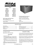
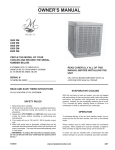
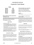
1
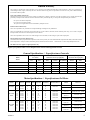
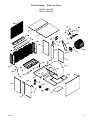
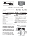
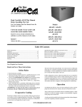
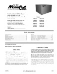
Read Carefully All Of This Manual
Before Installing The Unit
Lea Con Cuidado Todo Este Manual Antes De
Instalar La Unidad
Circle the model of your cooler and
record the serial number below.
Encierrre con un circulo el modelo de su
enfriador y escribe el número de série abajo.
Serial #
Número De Série
Models
ADA35
ASA35
ADA51
ASA51
AUA51
ADA5112
ASA5112
AUA5112
ADA71
ASA71
AUA71
ADA7112
ASA7112
AUA7112
Table Of Contents
Safety Instructions .......................................................................... 1
Operation......................................................................................1-2
Installation Instructions................................................................2-3
Electrical Wiring Diagram .............................................................. 3
Maintenance Section ....................................................................3-4
Troubleshooting .............................................................................. 4
Warranty .......................................................................................... 5
Specification Tables (Tablas de Especificaciones) .......................... 5
Parts List (ADA35, ASA35) .......................................................6-7
Parts List (51 & 71 Series Down Discharge) ...............................8-9
Parts List (51 & 71 Series Side Discharge).............................. 10-11
Parts List (51 & 71 Series Up Discharge) ................................12-13
Instrucciones en Español .........................................................13-16
Vea el Español en el interior.
Read And Save These Instructions
Safety Rules
1. Read instructions carefully.
2. Electrical hook up should be done by a qualified electrician, so that
all electrical wiring will conform to your local standards.
3. Always turn OFF POWER and UNPLUG motor and pump inside
the cooler before installing or performing any maintenance.
4. Your cooler will run on either 120V or 240V A.C., single phase,
60 Hz (cycle) current.
5. Motor and pump have a grounded, molded plug and an automatic
thermal overload switch which will shut motor off when it overheats.
The motor will restart automatically when it cools down.
WARNING: To reduce the risk of fire or electric shock, do not
use this fan with any “solid-state fan speed control device.”
This unit works on the same principle. Air is drawn across wet filter pads
where the air is cooled by evaporation and then circulated throughout
the building. It is this combination of cooled air and the movement of
air over the skin which makes it feel cool.
Unlike refrigeration systems which recirculate the air, an evaporative
cooler continually brings in fresh air while exhausting old air. You are
completely replacing the air every 2 to 4 minutes by opening windows or
doors or a combination of both. The air is always fresh, not stale, laden
with smoke and odors as happens with refrigerated air conditioning.
Operation
To eliminate the delivery of hot air when starting the cooler, start the
pump only for the first few minutes, then turn on the blower motor.
Evaporative Cooling
These coolers may be used without water for ventilation purposes. When
outside air is cool (for example, at night) or when humidity is high the
water pump can be turned off.
Evaporative cooling is nature’s way of cooling. When air is moved over
a wet surface, water is evaporated and heat is absorbed. When stepping
out of swimming pool with the wind blowing, evaporative cooling makes
you feel cool, even though the air may be warm.
A cooler can also be installed with a thermostat and attic exhaust dampers
to provide completely automatic operation.
110498-2
www.championcooler.com
12-09
Open Windows To Exhaust Air
An often misunderstood concept of evaporative cooling is the amount
of air that should be exhausted. How much should you open your
windows? The fact is that most people do not open their windows
enough. The following two methods will help you determine the amount
to open your windows.
• Mount motor. Install blower motor in the motor mount yokes, adjusting the yoke if necessary. Fasten with the provided mounting clips
(see Fig. 2). NOTE: Adjustable yoke will have to be reversed for 1
H.P. motors.
• Install pulley. Install the adjustable motor pulley so that it aligns
with the blower drive pulley (see Fig. 3) and tighten set screw.
First Method
You should allow an opening of at least 2 square feet (288 square inches)
for each 1000 CFM rating of your unit. Example: At 3320 CFM,
model ADA 51 (1/2 hp) requires 6.6 square feet (950 square inches)
of opening (3320/1000 * 2 = 6.6). Multiply the number of windows
by window width in inches and divide this into the number of square
inches required for your size unit. This will give you the height to
open windows. In this example, four 36 inch wide windows should be
opened 6.6 inches each.
Champion Air Balancing Method
1. Take a piece of tissue paper and cut it lengthwise into 3 equal
strips.
2. Turn your cooler on high cool.
3. Open one window at least six inches wide in each room that you
want to cool.
4. Take the piece of tissue paper and put it up against the screen of the
open window furthest from the cooler discharge opening. Let go of
it. It will do one of three things.
IF
THEN
It falls down.
CLOSE all of the windows one inch and try step 4 again.
IF
THEN
It plasters itself to the screen.
OPEN all of the windows one inch and try step 4 again.
IF
THEN
It stays on the screen lightly.
PERFECT. You are done. Enjoy your cooler.
NOTES:
• When switching to low cool, you must rebalance your home. Repeat
step 4.
• Once you balance your home you can cool some areas more than others
by opening those windows more and closing the others by the same
amount. Repeat step 4 to make sure your home is still air balanced.
Cooler Installation
Blower
Housing
Fig. 2
Adjustable
Yoke
Blower
Pulley
Fig. 3
Electrical Installation
WARNING: Disconnect all electrical service that will be used
for this unit before you begin the installation.
• Remove junction box. The electrical junction box is located in
the upper inside of the left center
post. Remove the two screws and
pull box out from panel for access
to plug wiring (Fig. 4).
Screws
Junction
Box
Fig. 4
• Hook up electrical. Electrical
hook up should be done by a
qualified electrician, so that all electrical wiring will conform to your
local standards. This unit is suppled with a 120V pump. For 240V
pump operation, a 240V pump must be purchased. The fan and pump
receptacles will support both 120V and 240V installations. See the
wiring diagrams for 120V and 240V installations on the following
page.
IMPORTANT: When a single speed motor is used, do not use the
red lead on the receptacle and motor plug wiring. Tape off end of
both of the red leads.
CAUTION: Pump receptacle is for grounded evaporative cooler
pump only. Do not plug anything else into receptacle.
WARNING: Make sure that cooler cabinet is properly grounded
to a suitable ground connection for maximum safety.
Water Connection
Wet
Module
NOTE: You can separate the wet module
from the blower module by removing the 4
bolts (2 bolts in ADA35 and ASA35) from the
wet module side (Fig. 1)
Mounting
Bolts
Motor Installation
Fig. 1
• Install motor cord. For typical 120V
installation, connect motor cord to motor using the following color
code: Black - Hi, Red - Low, White - Com., Green - Ground.
• Install overflow assembly. Remove
nut and place nipple through the hole in
the pan, with the rubber washer between
the pan and the head of the drain nipple
(Fig. 5). Screw on nut and draw up
tight against bottom of pan. Insert overflow pipe in nipple to retain water. The
overflow pipe may be removed to drain
pan when necessary. A garden hose
may be screwed on the drain nipple
to drain water away from your unit.
• Connect water supply line. Install
a sillcock and water valve on faucet
as shown by figure 6. Place the nut
and ferrule on the tubing and tighten
the nut until water tight. NOTE: Do
not connect the water supply to any
soft water applications.
Overflow Pipe
Nipple
Rubber Washer
Bottom Pan
Nut
Fig. 5
Faucet
Nut
enough to support the operating weight of the cooler when in use.
(For operating weight, see Specification Table.)
CAUTION: Never plug in cooler until installation is complete
and unit has been tested for rigidity.
CAUTION: Do not screw or drill within 5 inches of the bottom
of the wet module. You could puncture the reservoir.
CAUTION: If the unit is supported with legs at each corner,
the middle of the unit where the two sections
join must be supported as well.
Water Supply
Valve
Ferrule
CAUTION: Make sure that the mounting surface is strong
2
Motor
Pulley
Motor
Clips
Sillcock
Fig. 6
• Install float valve and fill pan. Refer to Fig. 7. Remove items 1, 2,
3, and 4. Insert float body (5) through hole in splash plate (8) (ADA/
110498-2
ASA35 only) and back post panel as
shown. Install washer (1) and nut (2).
Tighten to keep float from turning.
Place nut (4) and ferrule (3) on water
supply line. Connect to float fitting
and tighten until water tight. Bend
rod (6) to adjust float until water level
is about 1 inch below the top of the
overflow pipe. Slide float shield (7)
over float body (5) until it snaps into
place.
7
1
2
3
4
5
6
Fig. 7
8 (ADA/
ASA35)
will protect you from someone turning on
unit while you are working inside. This
should be done for your safety. Adjust
Decrease
Amperage
pulley to a larger diameter and readjust belt
tension, plug motor in, install inspection
panels, and retest amperage draw. Repeat
this process until correct amperage draw is
Fig. 9
attained. Increasing motor pulley diameter
increases amperage draw. Decreasing motor pulley diameter decreases
amperage draw (see Fig. 9).
CAUTION: Do not operate cooler with larger amperage draw
than specified on motor plate.
Bleed-Off
Installation of the bleed-off kit is recommended to increase the life of
the cooler. A bleed-off system is designed to prevent scale build up by
continually removing a small percent of the water in the pan.
• Install Bleeder Tee and Tubing. Refer to figure 8. Cut the Pump Hose
pump hose and insert the barbed
Bleeder Tee
Bleeder Tubing
ends of the bleeder tee into each
Restrictor
cut end. Insert one end of the
Overflow
bleeder tubing onto the bleeder
tee and run the other end out of
the cooler through the overflow
Fig. 8
pipe. Note: A restrictor clamp is
provided which, if desired, may be installed onto the bleeder tubing
to restrict the amount of water being bleed off. The amount of water
to bleed off depends on the quality of the water in your area. Start
with 1-2 gal/hr and increase if needed.
NOTE: No attempt should be made to completely install this unit
without the aid of an electrician or someone familiar with testing
amperage draw. Failure to comply with these instructions may void
your warranty.
Maintenance
WARNING : Before doing any maintenance be sure power
is off. At the time you remove either inspection panel be sure to
unplug motor and pump. This is for your safety.
Spring Start-Up
• Clean pads. A clean pad is more absorbent, efficient and will give
more cool air. Annually, or when required, using a garden hose with
nozzle, back wash to clean out the openings, then clean off the inlet
face any scale or other obstruction to the passages. Slight scraping
may be required to remove hardened scale.
Amperage Draw And Belt Tension
This unit is equipped with an adjustable motor drive pulley for adjusting
the blower wheel speed to the proper loading on different duct systems.
It is important that the motor drive pulley is adjusted to correct size to
assure maximum air delivery without damage to the motor. Be sure to
follow these instructions carefully.
• Adjust drive pulley. After the unit is completely installed, adjust
the drive pulley to the least diameter and adjust belt tension. See the
maintenance section for adjusting belt tension.
• Start cooler. Install both inspection panels, start pump, and allow to
operate until pads are wet.
• Check amperage. With pads wet and unit started, check amperage
draw with an amperage meter.
• Adjust pulley if necessary. If amperage draw is less than motor rating, turn off electrical power and remove inspection panels (top pan
for models ADA35 and ASA35). Unplug motor inside cooler, this
• Change pads if necessary. The pads should be replaced after 5 years
or if necessary. To change pads, remove top access panel, remove
grill, and disconnect water delivery tube. Remove water distributor
holder and lift out media sections. Replace with the same type media.
You can purchase them from your dealer.
IMPORTANT: In order to get the best performance from your cooling pads, they must be installed properly. If you have purchased a pad
with two equal angles, the following instructions can be disregarded.
Pads must always be installed with the steeper flute angle sloping down
towards the air entering
side (Fig. 10). The reason
is simple. The steeper
45°
Entering
angle puts more water on
Leaving Air
Air
the hot, dry, dirty side of
the pad where it is needed
15°
most. It also counteracts
the tendency of the air to
Fig. 10
push the water toward the
back of the pad.
Wiring Diagrams
120 Volts
Pump
Motor
Hi
Lo
Com.
Ground
Black
Red
White
Green
Blower Motor
110498-2
240 Volts
Blue/Black
White
Brown
Orange
Green
Pump
Black
Red
White
Orange
Green
Hi
Lo
Com.
Ground
= Wire Nut
To Switch
Blue/Black
White
Brown
Orange
Green
Pump
Motor
Hi
Lo
Com.
Ground
Black
Red
Orange
Green
Pump
Black
Red
White
Orange
Green
Hi
Lo
To Switch
Com.
Ground
= Wire Nut
Blower Motor
3
3 Lb.
• Check belt tension. A 3 lb. force
should deflect the belt 3/4 inches (see
Fig. 11). Readjust belt if needed.
3/4 Inches
• Oil bearings. The blower bearings and
cooler motor in this unit should be oiled
Fig. 11
with a few drops of non-detergent 20/30
weight oil once each year. The motor
does not need oil if it has no oil lines for oiling. Motors that have no
oil lines are lifetime oiled at the factory and require no further oiling
for the life of the unit.
CAUTION: Do not over oil. Over oiling can cause motor burn
out, due to excessive oil getting into motor winding.
• Clean pump. Cleaning the
pump is necessary once a year
at start-up. For your safety,
turn unit off and unplug motor
and pump. Remove the pump
from the mount slot. Remove
the base of the pump as shown
in Fig. 12. Clean the pump and
turn the impeller to ensure free
operation. Remove the pump
spout and check for any blockage. After cleaning, reinstall the base
onto the pump. Press firmly to make sure it is secure. Reattach the
pump to the mount in the cooler using the plastic retainer to ensure
that the pump will not overturn. Do not forget to replace the spout
and water delivery tube onto the pump outlet.
• Check bleed-off valve to be sure it is not clogged.
Winter Shut-Down
• Drain water. Always drain all of the water out of the cooler and water
supply line when not in use for prolonged periods, and particularly
at the end of the season. Keep the water line disconnected from both
the unit and water supply so that it does not freeze.
• Unplug motor and pump. When cooler is not used for extended
periods unplug the motor and pump from inside cooler.
Remove
Base
• Cover unit. To protect the life of the finish, a cover for the unit is
suggested in extended periods of non use.
Impeller
Fig. 12
By following the operating, installation, and maintenance suggestions
as outlined, you can get many years of efficient and satisfactory service
from your cooler. In the event additional information is desired, your
dealer will be more than glad to assist you in every possible way.
Troubleshooting Guide
Problem
Failure to
start or no
air delivery
Possible Cause
1. No electrical power to
unit
• Fuse blown
• Circuit breaker tripped
• Electric cord damage
2. Belt too loose or tight
3. Motor overheated
• Belt too tight
• Blower bearings dry
• Motor pulley diameter
too large
4. Motor locked
Inadequate
air delivery
with cooler
running
1. Insufficient air exhaust
2. Belt too loose
3. Pads plugged
4. Motor underloaded
Water drain- 1. Float arm not adjusted
ing onto
properly
roof
2. Overflow asembly leaking
Musty or
unpleasant
odor
4
1. Stale or stagnate water
in cooler
Remedy
1. Check power
• Replace fuse
• Re-set breaker
• Replace cord
2. Adjust belt tension
3. Determine cause of
overheating
• Adjust belt tension
• Oil blower bearings
• Adjust pulley to correct diameter
4. Replace motor
1. Open windows or
doors to increase air
flow
2. Adjust belt tension or
replace if needed
3. Clean pads
4. Adjust pulley
Problem
Remedy
Motor
cycles on
and off
1. Low voltage
2. Excessive belt tension
3. Blower shaft tight or
locked
4. Bearings dry
5. Motor pulley diameter
too large causing motor
overload
1. Check voltage
2. Adjust belt tension
3. Oil or replace bearings (Unplug unit)
4. Oil bearings
5. Adjust pulley so full
load ampere rating of
motor is not exceeded
Noisy
1. Bearings dry
2. Wheel rubbing blower
housing
3. Loose parts
1. Oil bearings
2. Inspect and realign
(Unplug unit)
3. Tighten loose parts
Inadequate
cooling
1. Inadequate exhaust in
house
Excessive
humidity in
house
1. Insufficient air exhaust
1. Adjust float
2. Tighten nut and overflow pipe
Possible Cause
1. Open windows or
doors to increase air
flow
2. Check water distribu2. Pads not wet
tion system
• Pads plugged
• Clean pads
• Clean
• Dist. tube holes clogged
• Pump not working prop- • Replace or clean
erly
pump (Unplug unit)
1. Open doors or windows
1. Drain pan and clean
pads
110498-2
Limited Warranty
This warranty is extended to the original purchaser of an evaporative cooler installed and used under normal conditions. It does not cover damages incurred through accident, neglect, or abuse by the owner. We do not authorize any person or representative to assume for us any other or different liability
in connection with this product.
Terms And Conditions Of Warranty
Lifetime Limited Coverage on water reservoir against any leakage due to defects in material. From date of purchase, if any original component part
provided by Champion Cooler fails due to defect in material or factory workmanship only, we will provide the replacement part as follows:
One year on the cabinet components.
Five years on the evaporative media.
Two years on the original blower motor if furnished by Champion Cooler.
Exclusions From The Warranty
We are not responsible for any incidental or consequential damage resulting from any malfunction.
We are not responsible for any damage received from the use of water softeners, chemicals, descale material, plastic wrap, or if a motor of a higher
horsepower than what is shown on the serial plate is used in the unit.
We are not responsible for the cost of service calls to diagnose cause of trouble, or labor charge to repair and/or replace parts.
How To Obtain Service Under This Warranty
Contact the Dealer where you purchased the evaporative cooler. If for any reason you are not satisfied with the response from the dealer, contact the Customer
Service Department: Champion Cooler, 5800 Murray Street, Little Rock, Arkansas 72209. 1-800-643-8341. E-mail: [email protected].
This limited warranty applies to original purchaser only.
Register your product online at www.championcooler.com/eac/onlineregistration-eac.htm
General Specifications / Especificaciones Generales
Weight (lbs.)
Peso (libras)
Models
Modelos
Cabinet Dimensions (in.)
Dimensiones De La Caja (pulgadas)
Width
Anchura
Duct Opening (in.)
Abertura De Ducto (pulgadas)
*Dry
Seco
*Operating
Lleno
Height
Altura
Depth
Profundidad
Width
Anchura
Height
Altura
35 Series
120
187
22 9/16
34
40
13 5/8
13 5/8
51 Series
177
227
28
42
45
17 3/4
17 3/4
5112 Series
190
257
28
42
49
17 3/4
17 3/4
71 Series
213
263
34 5/8
42
48
19 3/4
19 3/4
7112 Series
233
300
34 5/8
42
52
19 3/4
19 3/4
* Includes motor weight. / Incluye el peso del motor.
Motor Specifications / Especificaciones Del Motor
Models
Modelos
HP
C.V.
Motor #
Motor-N°
Speed
Velocidad
Volts
Voltios
*Amps
Amperaje
Weight (lbs.)
Peso (libras)
Motor Pulley #
Polea Del Motor-N°
35 Series
1/3
1/2
1/2
110445
110447
110475
2
2
2
115
115
230
7.2
9.8
4.9
17
18
15
110279-001
1/3
1/2
1/2
3/4
3/4
110445
110447
110475
110449
110480
2
2
2
2
2
115
115
230
115
230
7.2
9.8
4.9
13.8
6.9
17
18
15
22
21
110279-002
110279-004
110279-004
110279-004
110279-004
1/2
1/2
3/4
3/4
1
1
110447
110475
110449
110480
110471
110458
2
2
2
2
2
2
115
230
115
230
115
230
9.8
4.9
13.8
6.9
16
8
18
15
22
21
29
29
110279-002
110279-002
110279-004
110279-004
110279-003
110279-003
51 & 5112
Series
71 & 7112
Series
Model
Modelo
Drive Belt Part #
Correa - N°
ADA35
110209 (4L-430)
ASA35
110207 (4L-460)
ADA51 &
ADA5112
110208 (4L-520)
110229 (4L-530) - 3/4 HP
ASA51 &
ASA5112
110212 (4L-570)
AUA51 &
AUA5112
110222 (4L-510)
ADA71 &
ADA7112
110230 (4l-640)
ASA71 &
ASA7112
110213 (4L-670)
AUA71 &
AUA7112
110213 (4L-670)
*Amperage shown is from National Electrical Code for high speed. / Amperaje llistado es del código eléctrico nacional para la velocidad alta.
110498-2
5
Replacement Parts List / Lista De Piezas De Repuesto
When ordering parts, please be sure to furnish the following information on all orders. Failure to do so may delay your order. /
Al pedir piezas, incluya toda la información siquiente con su pedido. El no proporcionar toda esta información resultará en una demora.
1.
2.
3.
4.
5.
No.
N°
1.
2.
3.
4.
5.
6.
7.
8.
9.
10.
11.
12.
13.
14.
15.
15.
16.
17.
18.
19.
20.
21.
22.
23.
24.
24A.
25.
26.
27.
28.
29.
30.
31.
32.
33.
33A.
34.
35.
37.
38.
39.
40.
41.
Cooler model number / El modelo de su enfriador
Cooler serial number / Número de serie de la unidad
Motor HP / C.V. del motor
Description and part number / Descripción y número de pieza
Date of purchase / Fecha de compra
Description / Descripción
ADA35
Top, Blower Section / Tapa De La Sección De La Rueda ...........................................................................222130-028
Top, Wet Section / Tapa De la Sección De Agua..........................................................................................222130-029
Cabinet Wrapper, Blower Section / Envoltura De Caja De La Sección De La Rueda ................................322130-230
Cabinet Wrapper, Wet Section / Envoltura De Caja De La Sección De Agua .............................................222130-032
Blower Housing / Caja De La Rueda ...........................................................................................................324106-104
Cut-Off Plate / Placa Externa.......................................................................................................................224002-003
Blower Wheel / Rueda ..................................................................................................................................12BW
Shaft, Blower Wheel / Eje De La Rueda ......................................................................................................110182
Pulley, Blower Wheel / Polea De La Rueda.................................................................................................110274
Drive Belt / Correa .......................................................................................................................................110209
Pulley, Motor / Polea Del Motor ..................................................................................................................110279-001
Motor / Motor ...............................................................................................................................................*
Motor Mount Clip Set / Conjunto De Seguros Para Montar Motor ...........................................................314005-001
Motor Mount / Montura Del Motor..............................................................................................................314003-021
Electrical Cord, Motor (115V) / Cable Eléctrico Del Motor (115V)............................................................110364
Electrical Cord, Motor (230V) / Cable Eléctrico Del Motor (230V) ...........................................................110372-2
Bearings, Blower Wheel Shaft / Cojinetes Del Eje De La Rueda ................................................................110351
Electrical Junction Box / Caja De Empalme ................................................................................................322009-001
Receptacle, Motor / Toma De Corriente Del Motor .....................................................................................110393
Receptacle, Pump / Toma De Corriente De La Bomba ................................................................................110361
Retainer, Bearing Mount / Soporte Para La Montura De Los Cojinetes .....................................................218002-008
Water Distributor Housing / Caja Del Distribuidor De Agua ......................................................................281035
Media Shield (2 req.) / Protector Para El Medio Evaporativo (2 req.) .......................................................281025-005
Water Distributor Assembly / Sistema Del Distribuidor De Agua ...............................................................3D-26
Water Distributor Bracket, Right / Soporte Para El Distribuidor De Agua, Derecha .................................222004-005
Water Distributor Bracket, Left / Soporte Para El Distribuidor De Agua, Izquierda ..................................222004-003
Evaporative Media Set / Conjunto De Medio Evaporativo ..........................................................................310103
Support, Media / Soporte Para El Medio Evaporativo ................................................................................222130-027
Water Reservoir / Bandeja Acumuladora De Agua ......................................................................................281030
Pump Mount / Montura De La Bomba .........................................................................................................216003-008
Pump / Bomba ..............................................................................................................................................110436
Pump Screen / Malla Para La Bomba ..........................................................................................................281001-001
Pump Retainer / Sujetador De La Bomba ....................................................................................................110714
Float Valve / Flotador...................................................................................................................................FL-C
Float Shield / Salpicadero Del Flotador ......................................................................................................281006
Float Splash Plate / Placa Para Salpicaduras ..............................................................................................281025-006
Over Flow Assembly / Montaje De Desagüe ...............................................................................................3OA-3
Tube, Water Delivery / Tubo De Agua..........................................................................................................110716
Anti-Flattening Coil / Espiral Protectora.....................................................................................................110847
Grill / Parrilla...............................................................................................................................................224115-001
Filter Pad / Filtro De Poliester .....................................................................................................................110119-1
Support Bracket / Soporte Del Distribuidor .................................................................................................220101-008
Top Drain Assembly (2 req.) / Montaje De Desagüe De La Tapa (2 req.) ...................................................381012-006
ASA35
222130-028
222130-029
322130-130
222130-032
324106-204
224011-001
12BW
110182
110274
110207
110279-001
*
314005-001
314003-020
110364
110372-2
110351
322009-001
110393
110361
218002-008
281035
281025-005
3D-26
222004-005
222004-003
310103
222130-027
281030
216003-008
110436
281001-001
110714
FL-C
281006
281025-006
3OA-3
110716
110847
224115-001
110119-1
220101-008
381012-006
* See the motor specification table on page 5. / Vea la tabla de especificaciones del motor en la página 5.
NOTE: Standard hardware items may be purchased from your local hardware store.
NOTA: Artículos de uso corriente pueden comprarse en la ferretería de su localidad.
6
110498-2
Parts Drawing / Dibujo De Piezas
ADA35, ASA35
110498-2
7
Replacement Parts List / Lista De Piezas De Repuesto
When ordering parts, please be sure to furnish the following information on all orders. Failure to do so may delay your order. /
Al pedir piezas, incluya toda la información siquiente con su pedido. El no proporcionar toda esta información resultará en una demora.
1.
2.
3.
4.
5.
No.
N°
1.
2.
3.
4.
5.
6.
7.
8.
9.
10.
11.
12.
13.
14.
15.
16.
17.
18.
19.
20.
20.
21.
22.
23.
24.
25.
26.
27.
28.
29.
30.
31.
32.
33.
34.
35.
36.
37.
38.
39.
40.
41.
42.
43.
44.
Cooler model number / El modelo de su enfriador
Cooler serial number / Número de serie de la unidad
Motor HP / C.V. del motor
Description and part number / Descripción y número de pieza
Date of purchase / Fecha de compra
Description / Descripción
ADA51
Top, Cabinet / Tapa De La Caja ......................................................................... 222130-070
Top Access Panel / Panel Superior De Acceso .................................................... 222130-074
Bottom, Blower Section / Base De La Sección De La Rueda ............................. 322130-068
Bottom, Wet Module / Base De La Sección De Agua ......................................... 222130-072
Front Panel / Panel Del Frente ............................................................................ 222130-076
Inspection Panel (2 req.) / Panel De Inspección (2 req.)..................................... 224130-002
Center Post, Right / Poste Central, Derecho ....................................................... 222130-062
Center Post, Left / Poste Central, Izquierdo........................................................ 222130-063
Back Post, Right / Poste Trasero, Derecho ......................................................... 222130-064
Back Post, Left / Poste Trasero, Izquierdo .......................................................... 222130-065
Blower Housing / Caja De La Rueda .................................................................. 324130-202
Cut-Off Plate / Placa Externa.............................................................................. 224003-015
Blower Housing Supports (2 req.) / Soporte Para La Caja De La Rueda (2 req.) .. 218001-034
Grill / Parrilla...................................................................................................... 222130-078
Electrical Junction Box / Caja De Empalme ....................................................... 322009-001
Motor Mount / Montura Del Motor..................................................................... 314003-011
Motor Mount Clip Set / Conjunto De Seguros Para Montar Motor ................... 314005-001
Motor / Motor ...................................................................................................... *
Pulley, Motor / Polea Del Motor ......................................................................... *
Electrical Cord, Motor (115V) / Cable Eléctrico Del Motor (115V)................... 110372
Electrical Cord, Motor (230V) / Cable Eléctrico Del Motor (230V) .................. 110372-2
Shaft, Blower Wheel / Eje De La Rueda ............................................................. 110183
Blower Wheel / Rueda ......................................................................................... 16BW
Pulley, Blower Wheel / Polea De La Rueda........................................................ 110275
Drive Belt / Correa .............................................................................................. *
Bearings, Blower Wheel Shaft / Cojinetes Del Eje De La Rueda ....................... 110351
Receptacle, Motor / Toma De Corriente Del Motor ............................................ 110393
Receptacle, Pump / Toma De Corriente De La Bomba ....................................... 110361
Media Shield Right / Protector Para El Medio Evaporativo, Direcho ............... 281043-002
Media Shield Left / Protector Para El Medio Evaporativo, Izquierdo ............... 281043-001
Water Distributor Housing / Caja Del Distribuidor De Agua ............................. 281038-001
Water Distributor Tube / Tubo Del Distribuidor De Agua .................................. 3D-23
Evaporative Media Set / Conjunto De Medio Evaporativo ................................. 310117-001
Distributor Filter Pad / Filtro Del Distribuidor ................................................... 110120
Water Reservoir / Bandeja Acumuladora De Agua ............................................. 281041-001
Tube, Water Delivery / Tubo De Agua................................................................. 310716
Over Flow Assembly / Montaje De Desagüe ...................................................... 3OA-1
Float Valve / Flotador.......................................................................................... FL-C
Float Shield / Salpicadero Del Flotador ............................................................. 281006
Pump / Bomba ..................................................................................................... 110436
Pump Screen / Malla Para La Bomba ................................................................. 281001-001
Pump Mount / Montura De La Bomba ................................................................ 218002-012
Pump Retainer / Sujetador De La Bomba ........................................................... 110714
Anti-Flattening Coil / Espiral Protectora............................................................ 110847
Bleed-Off Kit / Equipo De Purga ........................................................................ 310586
ADA5112
222130-070
222130-075
322130-068
222130-073
222130-076
224130-002
222130-062
222130-063
222130-066
222130-067
324130-202
224003-015
218001-034
222130-078
322009-001
314003-011
314005-001
*
*
110372
110372-2
110183
16BW
110275
*
110351
110393
110361
281045-002
281045-001
281033-001
3D-23
310118-001
110120
281042-001
310716
3OA-1
FL-C
281006
110436
281001-001
218002-012
110714
110847
310586
ADA71
222140-053
222130-074
322140-051
222130-072
222140-055
224140-002
222140-045
222140-046
222140-047
222140-048
324140-202
224004-003
218001-037
222140-057
322009-001
314003-012
314005-001
*
*
110372
110372-2
110183
20BW
110276
*
110351
110393
110361
281044-002
281044-001
281038-001
3D-23
310117-002
110120
281041-001
310716
3OA-1
FL-C
281006
110436
281001-001
218002-012
110714
110847
310586
ADA7112
222140-053
222130-075
322140-051
222130-073
222140-055
224140-002
222140-045
222140-046
222140-049
222140-050
324140-202
224004-003
218001-037
222140-057
322009-001
314003-012
314005-001
*
*
110372
110372-2
110183
20BW
110276
*
110351
110393
110361
281046-002
281046-001
281033-001
3D-23
310118-002
110120
281042-001
310716
3OA-1
FL-C
281006
110436
281001-001
218002-012
110714
110847
310586
* See the motor specification table on page 5. / Vea la tabla de especificaciones del motor en la página 5.
NOTE: Standard hardware items may be purchased from your local hardware store.
NOTA: Artículos de uso corriente pueden comprarse en la ferretería de su localidad.
8
110498-2
Parts Drawing / Dibujo De Piezas
ADA51 / ADA5112
ADA71 / ADA7112
110498-2
9
Replacement Parts List / Lista De Piezas De Repuesto
When ordering parts, please be sure to furnish the following information on all orders. Failure to do so may delay your order. /
Al pedir piezas, incluya toda la información siquiente con su pedido. El no proporcionar toda esta información resultará en una demora.
1.
2.
3.
4.
5.
No.
N°
1.
2.
3.
4.
5.
6.
7.
8.
9.
10.
11.
12.
13a.
13b.
14.
15.
16.
17.
18.
19.
20.
20.
21.
22.
23.
24.
25.
26.
27.
28.
29.
30.
31.
32.
33.
34.
35.
36.
37.
38.
39.
40.
41.
42.
43.
44.
Cooler model number / El modelo de su enfriador
Cooler serial number / Número de serie de la unidad
Motor HP / C.V. del motor
Description and part number / Descripción y número de pieza
Date of purchase / Fecha de compra
Description / Descripción
ASA51
Top, Cabinet / Tapa De La Caja .....................................................................222130-070
Top Access Panel / Panel Superior De Acceso ................................................222130-074
Bottom, Blower Section / Base De La Sección De La Rueda .........................322130-069
Bottom, Wet Module / Base De La Sección De Agua......................................222130-072
Front Panel / Panel Del Frente ........................................................................322130-077
Inspection Panel (2 req.) / Panel De Inspección (2 req.) .................................224130-002
Center Post, Right / Poste Central, Derecho ...................................................222130-062
Center Post, Left / Poste Central, Izquierdo ....................................................222130-063
Back Post, Right / Poste Trasero, Derecho......................................................222130-064
Back Post, Left / Poste Trasero, Izquierdo ......................................................222130-065
Blower Housing / Caja De La Rueda ..............................................................324130-203
Cut-Off Plate / Placa Externa ..........................................................................224003-015
Blower Housing Support, Right / Soporte Para La Caja De La Rueda, Derecho..218001-035
Blower Housing Support, Left / Soporte Para La Caja De La Rueda, Izquierdo ..218001-036
Grill / Parrilla ..................................................................................................222130-078
Electrical Junction Box / Caja De Empalme ...................................................322009-001
Motor Mount / Montura Del Motor .................................................................314003-011
Motor Mount Clip Set / Conjunto De Seguros Para Montar Motor ...............314005-001
Motor / Motor ..................................................................................................*
Pulley, Motor / Polea Del Motor .....................................................................*
Electrical Cord, Motor (115V) / Cable Eléctrico Del Motor (115V) ...............110372
Electrical Cord, Motor (230V) / Cable Eléctrico Del Motor (230V) .................. 110372-2
Shaft, Blower Wheel / Eje De La Rueda .........................................................110183
Blower Wheel / Rueda .....................................................................................16BW
Pulley, Blower Wheel / Polea De La Rueda ....................................................110275
Drive Belt / Correa ..........................................................................................*
Bearings, Blower Wheel Shaft / Cojinetes Del Eje De La Rueda ...................110351
Receptacle, Motor / Toma De Corriente Del Motor ........................................110393
Receptacle, Pump / Toma De Corriente De La Bomba ...................................110361
Media Shield, Right / Protector Para El Medio Evaporativo, Direcho ..........281043-002
Media Shield, Left / Protector Para El Medio Evaporativo, Izquierdo ..........281043-001
Water Distributor Housing / Caja Del Distribuidor De Agua .........................281038-001
Water Distributor Tube / Tubo Del Distribuidor De Agua...............................3D-23
Evaporative Media Set / Conjunto De Medio Evaporativo .............................310117-001
Distributor Filter Pad / Filtro Del Distribuidor ...............................................110120
Water Reservoir / Bandeja Acumuladora De Agua .........................................281041-001
Tube, Water Delivery / Tubo De Agua .............................................................310716
Over Flow Assembly / Montaje De Desagüe ..................................................3OA-1
Float Valve / Flotador ......................................................................................FL-C
Float Shield / Salpicadero Del Flotador ..........................................................281006
Pump / Bomba ..................................................................................................110436
Pump Screen / Malla Para La Bomba .............................................................281001-001
Pump Mount / Montura De La Bomba ............................................................218002-012
Pump Retainer / Sujetador De La Bomba ........................................................110714
Anti-Flattening Coil / Espiral Protectora ........................................................110847
Bleed-Off Kit / Equipo De Purga ....................................................................310586
ASA5112
222130-070
222130-075
322130-069
222130-073
322130-077
224130-002
222130-062
222130-063
222130-066
222130-067
324130-203
224003-015
218001-035
218001-036
222130-078
322009-001
314003-011
314005-001
*
*
110372
110372-2
110183
16BW
110275
*
110351
110393
110361
281045-002
281045-001
281033-001
3D-23
310118-001
110120
281042-001
310716
3OA-1
FL-C
281006
110436
281001-001
218002-012
110714
110847
310586
ASA71
222140-053
222130-074
322140-052
222130-072
322140-056
224140-002
222140-045
222140-046
222140-047
222140-048
324140-203
224004-003
218001-038
218001-038
222140-057
322009-001
314003-012
314005-001
*
*
110372
110372-2
110183
20BW
110276
*
110351
110393
110361
281044-002
281044-001
281038-001
3D-23
310117-002
110120
281041-001
310716
3OA-1
FL-C
281006
110436
281001-001
218002-012
110714
110847
310586
ASA7112
222140-053
222130-075
322140-052
222130-073
322140-056
224140-002
222140-045
222140-046
222140-049
222140-050
324140-203
224004-003
218001-038
218001-038
222140-057
322009-001
314003-012
314005-001
*
*
110372
110372-2
110183
20BW
110276
*
110351
110393
110361
281046-002
281046-001
281033-001
3D-23
310118-002
110120
281042-001
310716
3OA-1
FL-C
281006
110436
281001-001
218002-012
110714
110847
310586
* See the motor specification table on page 5. / Vea la tabla de especificaciones del motor en la página 5.
NOTE: Standard hardware items may be purchased from your local hardware store.
NOTA: Artículos de uso corriente pueden comprarse en la ferretería de su localidad.
10
110498-2
Parts Drawing / Dibujo De Piezas
ASA51 / ASA5112
ASA71 / ASA7112
110498-2
11
Replacement Parts List / Lista De Piezas De Repuesto
When ordering parts, please be sure to furnish the following information on all orders. Failure to do so may delay your order. /
Al pedir piezas, incluya toda la información siquiente con su pedido. El no proporcionar toda esta información resultará en una demora.
1.
2.
3.
4.
5.
No.
N°
1.
2.
3.
4.
5.
6.
7.
8.
9.
10.
11.
12.
13.
14.
15.
16.
17.
18.
19.
20.
20.
21.
22.
23.
24.
25.
26.
27.
28.
29.
30.
31.
32.
33.
34.
35.
36.
37.
38.
39.
40.
41.
42.
43.
44.
Cooler model number / El modelo de su enfriador
Cooler serial number / Número de serie de la unidad
Motor HP / C.V. del motor
Description and part number / Descripción y número de pieza
Date of purchase / Fecha de compra
Description / Descripción
AUA51
Top, Cabinet / Tapa De La Caja ......................................................................... 322130-071
Top Access Panel / Panel Superior De Acceso .................................................... 222130-074
Bottom, Blower Section / Base De La Sección De La Rueda ............................. 322130-069
Bottom, Wet Module / Base De La Sección De Agua ......................................... 222130-072
Front Panel / Panel Del Frente ............................................................................ 222130-079
Inspection Panel (2 req.) / Panel De Inspección (2 req.)..................................... 224130-002
Center Post, Right / Poste Central, Derecho ....................................................... 222130-062
Center Post, Left / Poste Central, Izquierdo........................................................ 222130-063
Back Post, Right / Poste Trasero, Derecho ......................................................... 222130-064
Back Post, Left / Poste Trasero, Izquierdo .......................................................... 222130-065
Blower Housing / Caja De La Rueda .................................................................. 324130-204
Cut-Off Plate / Placa Externa.............................................................................. 224003-015
Blower Support Bracket (2 req.) / Soporte Para La Caja De La Rueda (2 req.) 218123-001
Grill / Parrilla...................................................................................................... 222130-078
Electrical Junction Box / Caja De Empalme ....................................................... 322009-001
Motor Mount / Montura Del Motor..................................................................... 314003-011
Motor Mount Clip Set / Conjunto De Seguros Para Montar Motor ................... 314005-001
Motor / Motor ...................................................................................................... *
Pulley, Motor / Polea Del Motor ......................................................................... *
Electrical Cord, Motor (115V) / Cable Eléctrico Del Motor (115V)................... 110372
Electrical Cord, Motor (230V) / Cable Eléctrico Del Motor (230V) .................. 110372-2
Shaft, Blower Wheel / Eje De La Rueda ............................................................. 110183
Blower Wheel / Rueda ......................................................................................... 16BW
Pulley, Blower Wheel / Polea De La Rueda........................................................ 110275
Drive Belt / Correa .............................................................................................. *
Bearings, Blower Wheel Shaft / Cojinetes Del Eje De La Rueda ....................... 110351
Receptacle, Motor / Toma De Corriente Del Motor ............................................ 110393
Receptacle, Pump / Toma De Corriente De La Bomba ....................................... 110361
Media Shield, Right / Protector Para El Medio Evaporativo, Derecho ............. 281043-002
Media Shield, Left / Protector Para El Medio Evaporativo, Izquierdo .............. 281043-001
Water Distributor Housing / Caja Del Distribuidor De Agua ............................. 281038-001
Water Distributor Tube / Tubo Del Distribuidor De Agua .................................. 3D-23
Evaporative Media Set / Conjunto De Medio Evaporativo ................................. 310117-001
Distributor Filter Pad / Filtro Del Distribuidor ................................................... 110120
Water Reservoir / Bandeja Acumuladora De Agua ............................................. 281041-001
Tube, Water Delivery / Tubo De Agua................................................................. 310716
Over Flow Assembly / Montaje De Desagüe ...................................................... 3OA-1
Float Valve / Flotador.......................................................................................... FL-C
Float Shield / Salpicadero Del Flotador ............................................................. 281006
Pump / Bomba ..................................................................................................... 110436
Pump Screen / Malla Para La Bomba ................................................................. 281001-001
Pump Mount / Montura De La Bomba ................................................................ 218002-012
Pump Retainer / Sujetador De La Bomba ........................................................... 110714
Anti-Flattening Coil / Espiral Protectora............................................................ 110847
Bleed-Off Kit / Equipo De Purga ........................................................................ 310586
AUA5112
322130-071
222130-075
322130-069
222130-073
222130-079
224130-002
222130-062
222130-063
222130-066
222130-067
324130-204
224003-015
218123-001
222130-078
322009-001
314003-011
314005-001
*
*
110372
110372-2
110183
16BW
110275
*
110351
110393
110361
281045-002
281045-001
281033-001
3D-23
310118-001
110120
281042-001
310716
3OA-1
FL-C
281006
110436
281001-001
218002-012
110714
110847
310586
AUA71
322140-054
222130-074
322140-052
222130-072
222140-058
224140-002
222140-045
222140-046
222140-047
222140-048
324140-204
224004-003
218001-038
222140-057
322009-001
314003-012
314005-001
*
*
110372-1
110372-2
110183
20BW
110276
*
110351
110393
110361
281044-002
281044-001
281038-001
3D-23
310117-002
110120
281041-001
310716
3OA-1
FL-C
281006
110436
281001-001
218002-012
110714
110847
310586
AUA7112
322140-054
222130-075
322140-052
222130-073
222140-058
224140-002
222140-045
222140-046
222140-049
222140-050
324140-204
224004-003
218001-038
222140-057
322009-001
314003-012
314005-001
*
*
110372-1
110372-2
110183
20BW
110276
*
110351
110393
110361
281046-002
281046-001
281033-001
3D-23
310118-002
110120
281042-001
310716
3OA-1
FL-C
281006
110436
281001-001
218002-012
110714
110847
310586
* See the motor specification table on page 5. / Vea la tabla de especificaciones del motor en la página 5.
NOTE: Standard hardware items may be purchased from your local hardware store.
NOTA: Artículos de uso corriente pueden comprarse en la ferretería de su localidad.
12
110498-2