1
4.3
4.4
4.5
4.6
4.7
4.8
4.9
4.10
4.11
4.12
4.13
4.14
4.15
4.16
4.17
4.18
5
6
6.1
6.2
6.3
7
7.1
7.2
7.3
7.4
REGULATION ON/OFF
REGULATION ON/OFF WITH NEUTRAL ZONE
REGULATION PID TO SINGLE ACTION
REGULATIÓN PID TO DOUBLE ACTION
REGULATIÓN PID FOR OPERATIONS MOTORIZED
WITH TEMPORARY POSITIONING
FUNCTIONS AUTOTUNING AND SELFTUNING
SCOPE OF SET POINT WITH CONTROLLED SPEED
AND AUTOMATIC COMMUTATION BETWEEN TWO
SET POINT (RAMPS AND TIME OF MAINTENANCE)
SOFT-START's
FUNCTION,
DELAYS
AND
PROTECTION
FUNCTIONING OF OUTPUT ALARM
FUNCTION ALARMA OF LOOP BREAK
FUNCTION OF TIMER
FUNCTION OF RAMPS
FUNCTIONING
OF
THE
KEY
PISANI
AND
MANAGEMENT DISPLAY
DIGITALS INPUTS
INTERFACE SERIAL RS 485
CONFIGURATION OF PARAMETERS WITH KEY USB
PROGRAMMABLE PARAMETERS TABLE
PROBLEMS, MAINTENANCE AND WARRANTY
SIGNS OF ERROR
MAINTENANCE
WARRANTY AND REPAIR
TECHNICAL DATA
ELECTRICAL CHARACTERISTICS
MECHANICAL CHARACTERISTICS
MECHANICAL DIMENSIONS AND FIXATION
FREQUENT QUESTIONS
1 – DESCRIPTION OF EQUIPMENT
INTRODUCTION
In the manual present there is contained the information
necessary for a correct installation and the instructions for the
utilization and maintenance of the product, therefore it's
recommends to read attentivly the following instructions.
This documentation has realized with supreme care,
nevertheless, OSAKA does not assume any responsibility of
the use of the same one.
The same thing is said for every person or company involved
in the creation of the manual present.
The present publication is an exclusive property of OSAKA
that prohibits his absolute reproduction and spreading, as well
as part of the same one, not to being of being expressly
authorized.
OSAKA is reserved of contributing aesthetic and functional
modifications at any time and without previous notice.
INDEX
1
1.1
1.2
2
2.1
2.2
2.3
2.4
2.5
3
3.1
3.2
3.3
3.4
4
4.1
4.2
DESCRIPTION OF EQUIPMENT
GENERAL DESCRIPTION AND ELECTION TEAM QB
DESCRIPTION OF FRONT PANEL
PROGRAMMING
FAST SETTING OF SET POINT
RESTORE PARAMETERS OF FACTORY
CODE
EXPRESS,
PROGRAMMING
LEVELS
PARAMETER
TYPES OF REGULATION
ACTIVE SET POINT SELECTION
WARNINGS OF INSTALLATION AND USE
USE
MECHANICAL ASSEMBLY
ELECTRICAL CONNECTIONS
SCHEME OF WIRING
FUNCTIONING
MEASURE AND VISUALIZATION
OUTPUT CONFIGURATION
1.1– GENERAL DESCRIPTION AND ELECTION TEAM QB
The models QB 32/48/98 are digital regulators with microprocessor
to two displays, with regulation ON/OFF, ON/OFF with dead zone,
PID with double action (direct and inverse), PID for operations
motorized of temporary positioning (The latter in model QB
32/48/98 PLUS (3PT).
For the regulation of the PID, the equipment possesses
AUTOTUNING's functions FAST AND NEW SMART TUNNING,
SELFTUNING with automatic calculation of the parameter FUZZY
OVESHOOT CONTROL.
The regulation of the PID relies on a particular algorithm to TWO
LIBERTAD'S DEGREES that it optimizes in an independent way
the services of regulation in presence of disturbances of the
process and variations of the SET POINT.
The equipment in addition offers the possibility of possessing an
interface of serial communication RS485 protocol of
communication MODBUS-RTU and speed of transmission up to
38400 baud. The value of the process is visualized in 4 digits, the
value of SET on 4 digits, whereas the condition of the outputs
distinguishes itself by 4 leds.
The equipment memorizes up to 4 Set-Points of regulation and can
have up to 4 outputs. 3 outputs can be foxgloves with relay and 1
analogical outputs (0/4 … 20mA or 0/2 ... 10V configurable), or up
to 4 static outputs (SSR).
The input is multiconfigurable and accepts probes of temperature
(thermocouples J, K, S, B, C, And, L, N, R, T; termoresistance
Pt100; thermistors PTC, NTC (Only in model QB 32-0); sensors of
infrarojo OSAKA IRS) and analog signals normalized (0/4 … 20mA,
0/1 … 5V, 0/2 … 10V, 0 ... 50/60mV, 12 ... 60mV). The equipment
has 2 digital incomes for free contact of tension and can have an
input for transformer of current for the function of warming of the
Break Alarm. Other important functions are:
Function of alarm Loop-Break, limitation of the power of output,
limitation of the speed of variation of the power of output, reaching
the Set Point to controlled speed, control for two times with time of
intermediate maintenance, function Soft-Start, protection of
parameters in different levels.
OSAKA – USER MANUAL LINE QB – V.1 - PAG. 1
OSAKA – USER MANUAL LINE QB – V.1 - PAG. 2
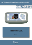
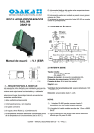
1.2 – DESCRIPTION OF FRONT PANEL
2 - PROGRAMMING
2.1 – FAST SETTING OF SET POINT
Press the "Set" button to confirm, and the display will visualized
"SPn" (where n is the number of Set Point active at that time) and
the programmed value.
To modify press the key "UP" to increase the value or "DOWN" to
decrease it.
These keys act with steps of a digit but if they keep pressed for
more than one second, the value it increases or decrementa rapidly
and, after two seconds in the same condition, the speed increases
quickly to reach the wished value.
Once programmed the wished value touching the key "Set" outputs
the fast programming mode or passes to the visualization of the
slogans of alarm AL1, AL2, AL3.
The output of rapid mode putting start of Set is given touching the
key "PISANI" or happening for all the parameters of the menu User
touching the key ENTER.
2.2 – RESTORE PARAMETERS OF FACTORY
The equipment allows returning to programme the parameters of
factory of rapid form, in case it is needed.
To load the parameters of factory they must follow the following
steps:
1. Press ENTER key for 5 seconds.
2. In the top display there will display message "PASS" and in
the low one he will prove to be 0.
3. Press keys DOWN/ UP and to establish password-481.
4. Press key ENTER.
5. The equipment will go out automatically and will do a
reseteo of parameter, showing in the top display the
message dFLt. Once the equipment returns to be ignited, the
equipment will return to be as the first time that was started.
2.3 – CODE EXPRESS AND PROGRAMMING LEVELS
PARAMETER
The new line of equipments QB comes with the new system of the
1 – Key ENTER
: Used to accede to the programming of the list of programming parameter CODE EXPRESS.
parameters of functioning and to confirm the selection. Also it This new tool allows the user to leave the team practically
advances to the near parameter inside the folder in which he is.
configurated only entering 2 codes of 4 digits.
2 – Key DOWN: Decreases the value of the parameter.
The following explains how to set parameters via express code:
3 – Key UP: Increase the parameter value. In automatic mode if 1- Prees Enter Key
during approximately 3 seconds.
you do a click, shows H or C followed by a number. This indicates The upper display will show “PASS”.
the power value in % output Heat (H) or Cold (C).
and
set the password 300 and
If we wattmeter function activated, the lower display will show U 2- Using the buttons
followed by the measured power.
press Enter
.
4 – Key PISANI
: When in the menu, is used to change folder 3- If no previously programmed code, in display shows “codE” and
or for going out of parameters by long press. Key of configurable “oFF” in the lower display.
functioning for the "USrb" parameter. It can be set to: Activate 4- Press button
for continue.
Auto-tuning or Self-tuning, put the computer to manual control, turn 5- The upper display will show "COD1" while the lower display
off the alarm, change the active Set Point, deactivate control, etc.. shows "0000".
(see par. 4.15).
6- At this moment it is necessary to choose the wished code of the
5 - Led OUTPUT1: Indicates the state of output OUT1
following, through the up and down keys “
and
” and then
6 - Led OUTPUT2: Indicates the state of output OUT2
7 - Led OUTPUT3: Indicates the state of output OUT3
press enter
.
8 - Led OUTPUT4: Indicates the state of output OUT4
9 - Led SET POINT: Indicates Set Point and programming
indicates parameter value. (See par. 2.3).
10 - Led AUTOTUNING IN PROGRESS: Indicates that the
autotuning / Self-tuning function are operating (flashing).
11 - Measuring PV: Normally indicates the process value.
12 – Unit(ºC/ºF) : indicates which unit is measuring the
temperature.
13 – Alarm: Alarm indication in progress.
14 – Manual mode: indicates that the controller is being controlled
in manual mode.
OSAKA – USER MANUAL LINE QB – V.1 - PAG. 3
As we were explaining a bit more above, the equipment has 3
*Note: Input PTC/NTC, only it is available in model QB 32-0
Note Control Mode: Column OUT3 only activates in PLUS version levels of access of parameters:
(4 Outputs).
The first level is the USER'S level.
Then, the upper display shows "cod2" while the lower display It is that level where they can accede to the parameters of rapid
form without need to enter no type of code of access.
shows "0000" or the value "cod2" stored in memory.
The second level is the Operator's level.
3- Using the buttons
and
There is established the value In this level one accedes by means of Password 20 (when shipped
of code2 of agreement by the following tables.
from the factory) and it allows us to establish the parameters that
are wished but appear linearly.
The third level is the Programmer's level.
In this level one accedes by means of the password 30 (when
shipped from factory) and it allows us to accede to all the
parameters of the equipment.
As explained a little above, the teams allowed across any of the
level move any parameter to our liking.
Later it explains how to do it:
4- Press the button
.
If the codes that are configured are correct, the upper display There are 2 ways to market the equipment parameters:
shows "CODE" and the bottom shows "Good".
1- Using SET UP OSAKA software + USB KEY (recommended)
5- Return to press again key
. Once you have pressed the
equipment will reset and will configure the parameters as has been
2- By means of manual procedure from the same equipment.
established in the CODE EXPRESS.
Note:
After using the method of "Code EXPRESS", always it will be
possible to modify the parameters using the method of normal
configuration. If the value of a parameter among those included in
the setup codes (COD1 - cod2) is modified, the change will acquire
equipment while the other parameters remain exactly the same.
If it is wished to programme by the manual procedure do the
following:
1. Press the key
during more than 3 seconds.
2. The upper display will show “PASS” thile the lower display shows
“0”.
3. Press the key
or
, and between with password -81.
If we enter into one of the parameters EXPRESS CODE by normal
4.
Press
the
key
.
procedure and we vary, the Code EXPRESS will return to mark
COD1 - COD 2 = oFF. Only it will return to show his value if it is The equipment will show the name of the first folder of
configuration of parameters InP
programmed by CODE EXPRESS.
5. By means the button
Select the folder of the parameter that
In case you want to program the equipment Normal shape or want it wishes to promote.
to change some parameter that does not include the Code Express
6. By means the button
select the parameter.
below normal procedure is explained:
7. The upper display will show the parameter name and the lower
display will show your current level of promotion. The promotion
The configuration parameters are in different "FOLDERS". Each
level is defined by a letter followed by a number:
folder defines all parameters related to a specific function (eg,
alarms, outputs, etc).
c: The letter shows that the parameter is accessible only from
PROGRAMMER level. In this case the number is forced to zero.
1. Press the button
during approxmately 5 seconds. The upper A: The letter shows that the parameter is in the OPERATOR level.
display will show “PASS” thile the lower display shows “0”.
Example: If there is wished that appears the Sens parameter first
2. Using the buttons
and
set the programmed password: and Dp second parameter. It must be programmed:
by default Password 20 (Operator level) or Password 30 Sens= A1
Dp= A2
(programmer level: all parameters).
o: The letter shows that the parameter is in the USER level. The
3. Press the button
.
number that shows is the position where you wish that show the
If the password is correct, the display will show the name of the first parameter to appear.
parameter FOLDER preceded by the symbol:
In other words, the upper display will show:
(FOLDER input parameters).
8. With the key
position.
or
this parameter is assigned the desired
Note:
If a different value from 0 is established, the letter "c" will change
automatically to to and the parameter happens to be automatically
the level of limited access.
PROMOTION PARAMETERS
An important part of the QB line is that in either model parameters
allow you to move the 3 levels of programming you have. Hereby it
and, maintaining
is possible to come to have a simple equipment for the final user, 9. To go the level of USER parameter, press
simple to programme and can avoid badly use of the clients at the the pressure, press
. The letter will change of "A" to "o"
moment of touching parameters.
changing automatically the level.
This procedure is called Promotion of parameters.
OSAKA – USER MANUAL LINE QB – V.1 - PAG. 4
10. When you need to go out of the procedure of promotion, press The use of equipment for standard applications not expressly
the button
and maintain pressure for over 10s. The equipment provided in norm cited above, should provide all measurement and
adjustments necessary protection.
shows the "standard display".
The equipment must be adequately protected and away from
liquids, dust, grease and dirt. They must be accessible only with the
2.4 – TYPES OF REGULATION
use of a right tool and safety system (except the front).
The equipment has 3 operating modes: automatic regulation
The devices can NOT be used in dangerous environments
(REG), Stand-by (Stand-by) and manual control (OPLO).
(flammable or explosive) without adequate protection.
It is recalled that the installer must ensure that the norm for
The team can move from one state of operation to another in
electromagnetic compatibility is respected after implantation in the
different ways:
installation of equipment, eventually using the right filters if is
- From Oper parameter inside the folder Pan
needed.
- From the “PISANI" key conveniently programmed on par. "USrb"
In case of failure or malfunction of measuring and control
("USrb” = OPLO; “USrb” = St.by) can go from nivel "rEG” the level
equipment that can create dangerous situations or damage to
programmed in the parameter and vice versa.
persons, things, animals or products (defrost food or changes in
- From digital input conveniently programmed on par. "DiF” it is
their ideal state), it is recalled that the facility should be equipped
possible passed to the "REG” mode to "St.by" mode.
with electronic devices or electromechanical safety and warning
- Default team is active in the "REG” mode.
system.
If any of the three levels is programmed, is scheduled to begin
They should be placed outside the measuring and control
booting the computer with the last programmed mode before
equipments, possible protective devices, responding to specific
shutdown.
safety requirements that are covered by the norm of the product or
suggest the common sense.
AUTOMATIC REGULATION (rEG) - The mode of automatic For your own safety, is highly recommended fulfilling the
regulation is the normal way of functioning. During the automatic instructions provided above.
regulation, it is possible to visualize the regulation power on the
3.2 – MECHANICAL ASSEMBLY
display SV pressing the key “
”.
The values visualizables of power vary of H100 (100 % of power in Requirements
This equipment is designed for a permanent installation, only for
heat output) to C100 (100 % of power in output of Cold).
use in interiors, in an electrical panel that covers the back
DEACTIVATED REGULATION (Stand - by) - East way deactivates framework. The terminals are exposed and the wiring in the part of
the automatic control, and deactivates the outputs of control. In this behind.
way the equipment works as an indicator.
When the equipment is in way Stand - by, the top screen will show Select a location of assembly that has the following characteristics:
the measured value, whereas the low screen will show alternately
1. It must be of easy access;
the Set Point and the message "St.bY".
2. Minimal vibrations and no impact;
MANUAL REGULATION (OPLO) - This option allows programming 3. Without corrosive gases;
manually the percentage of power given in the output of the 4. Without water or other fluids (it is to say, of condensation);
5. Temperature enviroment be according to the operative
regulator deactivating the automatic regulation.
When the equipment is activated in manual regulation, the temperature (0 ... 50°C);
6. The relative dampness be according to the specifications of the
percentage of power that acts is visualized in the top display (SV).
The lower display will show alternately the power of output equipment (20 ... 85 %);
[preceded for H (for heat action) or C (for action of cold)] and the
The equipment can be mounted on the panel, with a maximum
message OPLO, which also can be modified by the keys “
” 15mm thick.
When the maximum frontal protection (IP65) is desired, the
and “
”.
optional board must be installed.
2.5 – ACTIVE SET POINT SELECTION
The equipment allows to form up to 4 Set Points of regulation The equipment can be mounted in the panel, with a maximum
("SP1", "SP2", "SP3", “SP4") and to select which of them will be thickness of 15mm. When is wished the front maximum protection
(IP65), the optional meeting it must be installed.
active.
The maximum number of set points comes determined by the
]
3.3 – ELECTRICAL CONNECTIONS
parameter "nSP" in the folder of parameters “ SP “.
Perform the wiring connecting only one wire to each terminal and
The active Set point can be selected:
following diagram, controlling that the tension of supply is adapted
]
for the equipment and that the load of the actuadores joined the
- For the parameter "A.SP" in the group of parameters “ SP “.
equipment should not be superior to the allowed current.
- By means of the key "PISANI" if the parameter "USrb" = CHSP.
- By means of the digital input suitably programmed across of par. The equipment is prepared to be permanently connected within a
panel is not equipped with either switches or internal overvoltage
"DiF" ("diF" = 18, 19, 20)
The Set point "SP1", "SP2", "SP3", "SP4", will be visible depending protection devices.
on the maximum number of Set points selected in the parameter It is recommended to install a switch / isolator bipolar type as the
"nSP" and will be configured with a value understood between the disconnect device, which interrupts the power supply of the
values programmed in the par. "SPLL" and the value programmed equipment.
This switch should be placed as near as possible to the team and
in the par. "SPHL".
in a readily accessible location by the user.
In addition one recommends to protect adequately all the
3 – WARNINGS OF INSTALLATION AND USE
connected circuits to the equipment with devices (ex. fuses)
proportionate to the effective current circuits.
3.1 - USE
Use cables with proper insulation adapted to the voltage,
The devices are made as measuring and regulating equipment in temperature and environmental conditions, and make the sensor
accordance with EN 61010-1 norm for operation up to an altitude of wires from the entrance to keep away from power cords and other
2000 mts.
power cables to avoid induction of electromagnetic interference.
OSAKA – USER MANUAL LINE QB – V.1 - PAG. 5
If some cables used for the wired up one are protected, one
recommends to connect them to land for an alone side.
Finally check that the programmed parameters are those wished
and that the application works correctly before connecting the
outputs to the actuadores to avoid anomalies in the installation that
hurts could cause to persons, things or animals.
OSAKA and his legal representatives are not done in any way
responsible by eventual hurts to persons, things or animals as
consequence of manipulations, improper use, mistaken
employment or in any case without going in conformity with
the characteristics of the equipment.
3.4 – SCHEME OF WIRING
4 - FUNCTIONING
4.1 – MEASURE AND VISUALIZATION
]
All parameters relating to the measure are contained in the folder “
InP”.
By means of parameter "SEnS" it is possible to select the type of
probe of input that is needed:
- for termopares J (J), K (CrAL), S (S), B (b), C (C), E (E), N (n), R
(r), T (t), or for sensors of infrarojo OSAKA series IRS range with
linearización IRS J (Ir. J) or IRS K (Ir.cA)
- for termoresistencia Pt100 IEC (rtd) or thermistor PT1000 [Rtd,
Ptc or Ntc] from calibration of agreement to IN 60751/A2
- for sign normalized of current 0…20mA (0.20) or 4...20 mA (4.20)
- for signs normalized of tension 0...60mV (0.60), 12…60mV
(12.60), 0…1V (0.1), 0…5V (0.5), 1...5V (1.5), 0...10V (0.10) ó
2…10V (2.10).
By changing these parameters, one advises to extinguish and to
ignite the equipment to obtain a correct measure.
For the equipments with input of probe of temperature (tc, rtd) it is
possible to select, by means of the parameter "Unit" the unit of
measure of temperature (°C, °F) and, by means of the parameter
"dP" the resolution of wished measure (0=1 °; 1=0,1 °).
As for the equipments programmed with input of normalized analog
signal, it is necessary first of all to programme the resolution
wished in the parameter "dP" (0=1; 1=0,1; 2=0,01; 3=0,001) and in
the parámetro "SSC/FSC" the value that the equipment must
visualize correspondent to the lower/superior limit sign of input (1999 ÷ 9999).
IMPORTANT NOTE: Input NTC/PTC alone disponilbe in model
QB 32-0.
The model QB 32-0 does not admit probes PT 100.
The new QB range allows doing a calibration of the mistakes of
measure to 2 points of the process, making the set more precise
between sensor + equipment and perfecting the process with the
minimal possible mistake.
]
These parameters can be found in the folder “ CAL.”
The parameters that intervene are:
AL.P – Adjust Low Point
AL.o - Adjust Low Offset
AH.P – Adjust High Point
AH.o - Adjust High Offset
OSAKA – USER MANUAL LINE QB – V.1 - PAG. 6
Later we explain a possible practical example of calibration:
P.Et 1/2 = Program Event 1/2
Or.bo = out of range or power failure indicator output
Example: climatic Chamber with a working range of: 10 to 100°C.
P.FAL = power failure indicator
bo.PF = Out of range indicator, power failure and power failure
1. Establish in the parameter AL.P = 10 and parameter AH.P = 100. St.bY = indicator Stand-by
These are the ranges of work of the supposed climatic chamber.
dif. 1/2 = The output repeats the condition digital input 1/2
On= output 1 always on
2. With the help of a calibrator, look at how much of detour is on
the lower part of the process (in this case to 10 degrees) and to Note: The timer functions and ramp or program is only available
establish this difference in the parameter AL.o.
from the RAMP model.
3. With the help of the gauge, to look how much at detour is in the
top part of the process (in this case 100 degrees) and to establish In the parameter io4.F is selected the function that required for the
this difference in the parameter AH.o.
output or input 4. This output function shared with digital input 2. So
if wish use output 4 as a digital input extra or feeder probe, this
Hereby, the process will remain corrected in all his curve, along the output will be lost. Let's see how we can configure it.
whole range.
on= Output 4 always ON (used as a power source of power);
out4 = output SSR
dG2.c = Digital input 2 for contact closure;
dG2.U = Digital input 2 driven by 12 ... 24 VDC.
By means of par. "FiL” can programme the constant of time of the
" Filter software relative to the input" ó "Digital filter of input", so that
it is possible to diminish the sensibility to the inconveniences of
measure.
In case of mistake of measure, the equipment provides in output,
the power programmed in the par. "OPE".
This power will be calculated based on the cycle time programmed
by the regulator ID, whereas for the regulators ON/OFF it is
considered automatically a time of cycle of 20 seg. (Eg in case of
probe error with ON / OFF control and " OPE" = 50, the regulation
output will be activated for 10 sec. , Then stays off for 10 sec. until
the mistake of measure stays).
- ANALOG OUTPUT 0/4...20 mA o 0/2...10 V (o1t) (Only RMA
models, OUT1 is the ANALOG OUTPUT):
Par. “o1F”:
These parameters can be programmed for the following functions:
NonE = Output not used
H.rEG = Heating output
c.rEG = Cooling output
r.inP = Measure retransmission
r.Err = Error (sp - PV) retransmission
r.SP = Set point retransmission
r.SEr = Serial value of the RS485
Across the parameter "o1t" is possible to choose the type of
analogical output that is wished to choosing between:
0-20 = 0...20 mA
4-20 = 4...20 mA
0-10 = 0...10 V
By means of par. "InE" it is possible to establish which are the 2-10 = 2...10 V
conditions of mistake at the input that they lead the equipment to
providing in output the power programmed in the couple "OPE".
In the parameters Ao1L and Ao1H are programmed the limits lower
The possibilities of par. "InE" are:
= Or: the condition occurs in case of over-range.
= Ur: the condition occurs in under-range.
+ = Our: the condition occurs in case of over-range or under-range.
]
Through of par. "diSP" present in the group “ PAn” establishes the
normal visualization of the display SV that can be the active Set
Point (SPF), the power of regulation of output (Pou), the operative
Set Point when there are active sections (Spo), the slogan of alarm
AL1, 2 or 3 (AL1, AL2 or AL3).
4.2 – OUTPUT CONFIGURATION
The outputs of the equipment can be configured in the parameter
]
folder “ Out”, where they are, depending on the type of outputs
(digital or analog) various parameters.
- DIGITAL OUTPUT with relay or with SSR:
Par. "O1F, o2F, o3F, o4F"
These parameters can be programmed for the following functions:
NonE = Output not used
H.rEG = Heat output
c.rEG = Cold output
AL = Alarm output
t.out = Timer output
t.HoF = Timer output on Hold-OFF
P.End = end of program indicator
P.HLd = pause indicator program
P.uit = indicator program phase maintenance
P.run = indicator RUN program
and Superior of the analogical output in case he needs. Only it will
appear when the output is configurated like r. IMP, r. Err, r. SP or
r.SEr.
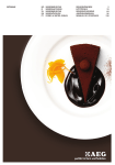
4.3 - REGULATION ON/OFF (C.rEG)
All parameters related to the regulation "ON / OFF" are contained
]
in the “ rEG” folder.
This mode of regulation is possible programming the parameter
"Cont" = On.FS or = On.FA and it acts on the output configurated
as H.rEG or C.rEG depending on the measure, of the Set point
active "SP" and of the histéresis programmed "HSEt".
The team employs a regulation "ON / OFF" with symmetric
hysteresis if "Cont" = On.FS or with asymmetrical hysteresis if
"Cont" = On.Fa.
The regulator behaves of the following form: in case of inverse
action, or of heat ("FunC" =HEAt), disables the output when the
process value reaches the value [SP + HSEt] in case of
symmetrical hysteresis, or [SP] in case of asymmetrical hysteresis
and is activated when the value is below [SP - HSEt].
Vice versa, in case of direct action or cooling ("OXF" = c.rEG),
disables the output when the process value reaches the value [SP HSEt] in case of symmetrical hysteresis, or [SP] for asymmetric
hysteresis reactivate when it is above the value [SP + HSEt].
OSAKA – USER MANUAL LINE QB – V.1 - PAG. 7
The latter parameter eliminates the disturbances in the load
(overshoot) of the start up of the process or of Set Point's change.
It should be noted that a low value of the parameter reduces the
"overshoot" whereas a high value increases it.
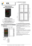
4.4 - REGULATION
(C.rEG/H.rEG)
ON/OFF
WITH
NEUTRAL
ZONE
All parameters related to the regulation "ON / OFF" Neutral Zone
]
are in the “ rEG” folder.
The operation is feasible when 2 outputs are configured as H.rEG
and C.rEG respectively.
The Dead Zone operation is used for the control of the facilities that
possess an element that causes a positive increase (eg. Heater,
humidifier, etc.) And an element which causes a negative increase
(eg ad . Cooling , dehumidifying , etc.).
The control functions works on the configurated outputs depending
on the measure of Set Point "SP" active, and hysteresis "HSEt"
programmed.
The regulator behaves in the following way: Turn off the outputs
when the process value reaches the Set and active output H.rEG
when the process value goes below value [SP-HSEt] or lights the
output C.rEG when process value is greater than [SP + HSEt].
For following, the element causing a positive increase has to be
connected to the output programmed as H.rEG, while the element
of negative growth, will go unit with the output configured as C.rEG.
4.5 – REGULATION PID TO SINGLE ACTION
All parameters related to PID regulation are contained in the
]
carpeta “ rEG” folder.
The mode PID regulation type action is feasible simply by
]
programming the parameter "Cont" (contained in the “ rEG”
folder) = Pid and works on the output of regulation in function to Set
Point "SP" active, mode H.rEG operation or C.rEG, and the result
of PID control algorithm with two degrees of freedom of the
equipment.
Todos los parámetros relacionados a la regulación PID están
]
contenidos en la carpeta “ rEG”.
To achieve good stability of the variable in case of fast processes
and actuator control with digital output, cycle time "tcc and tcH"
should have a low value with a very frequent intervention of the
regulation output.
In this case the use of a static relay (SSR) for the control actuator is
recommended. (Use output 4 Programmed as SSR).
The algorithm of regulation PID of simple action of the equipment
facilitates the programming of the following parameters:
"Pb" - Proportional Band
"ti" - Integral Time
"Td" - Derivative time
"tcH" - Time Output Cycle Heating
"tcc" - Time Out cliclo cooling
"rS" - Manual Reset (only if "ti = 0)
“FuOC” - Fuzzy Overshoot Control
1: Value "FuOC" OK
2: Value "FuOC" too high
3: Value "FuOC" too low
4.6 – REGULATIÓN PID TO DOUBLE ACTION (H.rEG + C.rEG)
]
All parameters related to PID control are contained in the “ rEG”
folder.
The Double Action PID regulation is used to control of facilities
where there is an element which causes a positive increase (eg.
heat) and an element which causes a negative increase (eg.
cooling) and acts when they are configurated 2 outputs as H. rEG
and C.rEG and programming the par. "Cont" = Pid.
The element causing a positive increase will go connected to the
output programmed as H.rEG while negative growth element will go
connected to the output programmed as C.rEG.
The mode of regulation PID double action acts on both outputs
C.rEG H.rEG and Set Point "SP" depending and the result of PID
control algorithm with two degrees of freedom of the equipment.
To achieve good stability of the variable in case of fast processes
and control actuators with digital outputs, cycle times "tcc" and "tch"
should have a low value with a very frequent intervention of the
regulation outputs.
In this case the uses of a static relay (SSR) to control actuators are
recommended.
The PID control algorithm of double action equipment facilitates the
programming of the following parameters:
"Pb" - Proportional Band
"ti" - Integral Time
"Td" - Derivative time
"tcH" - Time Output Cycle Heating
"tcc" - Time Out cliclo cooling
"rS" - Manual Reset (only if "ti = 0)
“FuOC” - Fuzzy Overshoot Control
"rcG" - Power Ratio or relation between power of the element in
the output C.rEG and power of the element controlled for the output
H.rEG
4.7 – REGULATIÓN PID FOR OPERATIONS MOTORIZED WITH
TEMPORARY POSITIONING (H.rEG + C.rEG) (Only PLUS
version available (3PT))
All parameters related to PID control for motorized actuators are
]
contained in the “ rEG” folder.
This type of regulation is in use for the control of facilities provided
with an operation motorized with controls of opening and closing of
digital type that acts when configured 2 outputs respectively as
H.rEG and c.rEG are, programming the par. "Cont" = 3 Pt
The control opening drive shall be provided with the output
configured as H.rEG while closure controlling shall be provided with
the output configured as C.rEG.
The mode PID regulation for motorized operation acts on the
outputs H.rEG (heat or direct process) and C.rEG (cold or reverse
process) based on the Set Point “SP" active and the result of PID
control algorithm with two degrees of freedom of equipment.
The control system used does not provide feedback to set the
current position of the drive.
OSAKA – USER MANUAL LINE QB – V.1 - PAG. 8
If the actuator was not provided with safety contacts that interrupt
the operation once run , it is necessary to provide the installation of
these contacts (SQO, SQC) as shown in Figure
The PID regulation algorithm for motorized actuators with time
positioning facilitates the setting of the following parameters:
"Pb" - Proportional Band
"ti" - Integral Time
"Td" - Derivative time
"rS" - Manual Reset (only if "ti = 0)
“FuOC” - Fuzzy Overshoot Control
"Str.t": carrer running time.
Is the time, expressed in seconds, which needs the drive to move
to the position "normally open" to "closed".
"db.S”: minimum value of regulation
It is the first value that must be reached regulation (in %) having
effect on the output. Used to prevent the control from intervening
frequently.
-2 = Oscillating -tune with auto-matic start at the first
power up only
-1 = Oscillating auto-tune with auto-matic restart at every
power up
0 = Not used
1 = Fast auto tuning with automatic restart at every power
up
2 = Fast auto-tune with automatic start the first power up
only
3 = FAST auto-tune with manual start
4 = FAST auto-tune with automatic restart at power up and
after a set point change
5 = SMART-tune with automatic restart at every power up
6 = SMART-tune with automatic start the first power up
only
7 = SMART-tune with manual start
8 = SMART-tune with automatic restart at power up and
after a set point change
NOTE: the FAST autotuning type is particularly fast and does not
show any effect, since he calculates the parameters of the
controller during the phase of scope of the Set Point.
For proper implementation of the FAST autotuning type, it is
necessary that in the beginning of cycle there is a certain difference
regarding the process variable and the set point. For this reason
the equipment starts the autotuning only when:
- The Fast autotining does not start when the Set Point is close to
the initial reading.
- When the measured variable varies irregularly during the tuning
cycle (for the motive due to the process the variable ascends or
descends).
In this case we recommend using the autotuning of the oscillatory
4.8 – FUNCTIONS OF AUTOTUNING AND SELFTUNING
type, which acts in some cycles of ON-OFF control which leads the
All parameters related to the AUTOTUNING and SELFTUNING process value to oscillate around the value of set point completed
]
function are contained in the “ rEG” folder.
and which happens to PID regulation with the parameter calculated
The AUTOTUNING's function and the SELTUNING they allow the autotuning.
automatic tuning of the regulator PID.
The AUTOTUNING's function calculates the parameters PID 6) Output programming parameters.
across a cycle of tuning type SMART, which the parameters are 7) Connect the equipment to the control system.
memorized and during the regulation they are kept constant (in 8) Enable autotuning turning off and turning on the device if "Auto"
case of mistake ERAT put calculation pid oscillatory or fast, = 4,5,1,2 or 2 or by selecting the "tunE" option.
programming autotuning with a value auto = negative, [eg,-1,-2,-3,- At this point the auto-tuning function is activated and is signaled
4])
using the flashing LED TUNE.
The controller acts when the equipment's operations have ended
The SELFTUNING function (rule based in "TUNE-IN") motorizes and the parameters of PID control are the suitable.
regulation and the continuous calculation of the parameters during If the conditions of the process values are not checked for
regulation.
autotuning, the display will show “erat “. This indicates that the
Both functions automatically calculate the following functions:
equipment can not continue operations and the equipment will get
"Pb" - Proportional Band
in the normal mode of regulation and the parameters set above.
"tcc" - Time Out cliclo cooling
To clear the error “erat " is enough by pressing the Enter key.
"tcH" - Time Output Cycle Heating
In the event that is experienced an error of probe, the equipment
"ti" - Integral Time
will interrupt the running cycle.
The calculated value of autotuning will be automatically saved to
"Td" - Derivative time
your computer to complete the proper execution cycle in autotuning
“FuOC” - Fuzzy Overshoot Control
parameters relative to PID regulation.
And for the Double Action PID regulation also:
"rcG" - Relationship P C.rEG / P H.rEG
Note: The equipment come configured factory to perform autotuning on all versions of equipment ("Auto" = 7).
To activate the AUTO-TUNING function proceed as follows:
1) Program and activate the desired Set Point.
2) Program the parameter "Cont" = PID = 3 or Pt, if the equipment To activate the SELF-TUNING function proceed as follows:
1) Establish and activate the desired Set Point.
controls a motorized drive with time positioning.
3) If the control is of simple action, program the parameter "Func" 2) Program the parameter "Cont" = Pid = 3Pt or if the equipment
controls a motorized drive with time positioning.
according to the process to be controlled by the output.
4) Set 2 outputs as C.rEG H.rEG as if the equipment controls an 3) If the control is a simple action set the parameter according to
installation with dual action or a motorized drive with time control process through the output.
4) Configure 2 outputs as C.rEG and H.rEG if the equipment
positioning.
controls a dual action installation or a motorized drive with time
5) Program the parameter "Auto" as:
positioning.
Selection of autotuning:
-4 = Oscillating auto-tune with automaticrestart at power 5) Program the parameter "SELF" = yes
6) Exit from the parameter programming.
up and after all point change
7) Connect the equipment to the controlled installation.
-3 = Oscillating auto-tune with manual start
OSAKA – USER MANUAL LINE QB – V.1 - PAG. 9
8) Activate self-tuning by selecting the "Tune" option in the main
menu (or by correctly programming key "PISANI" conveniently
scheduled).
When the Self-tuning function is not activated, the TUNE LED is
permanently mode fixed, and all the PID parameters of regulation
(“Pb ",” ti”, " td”, ecc.) are not visualized any more.
To stop the Autotuning cycle or off Selftunting select the “SELF”
menu any states regulation: "rEG",”OPLO" or "OFF".
If the equipment shuts down during the auto-tuning or self-tuning
function activated, the functions will be integrated into the take-off.
In case that stop the compressor for temperature, until the time
established in the parameter does "cPdt" not happen, always and
when the temperature is not superior to the SP + HSET, the
equipment will not return to start the compressor for protection.
4.11 – FUNCTIONING OF OUTPUT ALARM (AL1, AL2, AL3)
For the configuration the alarm functioning whose involvement is
linked to the process value (AL1, AL2, AL3) is first necessary to
establish to which output has to correspond the alarm.
To do this one needs configure the folder for all parameters " ] Out"
4.9 - SCOPE OF SET POINT WITH CONTROLLED SPEED AND parameters relative to the outputs you want to use as alarms (" 1F",
AUTOMATIC COMMUTATION BETWEEN TWO SET POINT "O2F", "O3F", "O4F") programming the parameter relative to the
(RAMPS AND MANINTENANCE TIME)
desired output as AL.
Then we associate an alarm to the desired output through o1AL,
All parameters related to the ramps functioning are contained in the o2AL, o3AL and o4AL parameters.
]
“ rEG” folder.
You can achieve the set point is reached in a given time (in any Note: In all the following examples relate to AL1 alarm. Naturally
the operation of the other alarms is the same,
case never greater than the time that the system needs naturally).
This can be useful in those processes (heating or chemical By accessing “]AL1” folders, the parameters relating to alarms are
treatments, etc.) whose Set point must be reached gradually, in programmed:
pre-established times.
Also you can get once reached the first Set (SP1) the equipment "AL1t” - ALARM 1 TYPE
automatically switching to the second Set (SP2) after a "Ab1" – ALARM 1 FUNCTION
programmable time, thus obtaining a simple automatic thermal “AL1” – AL1 THRESHOLD
cycle.
“AL1L” – FOR HIGH AND LOW ALARMS, IT IS THE LOW LIMIT
These functions are available for all types of programmable OF THE AL1 THRESHOLD; FOR BAND ALARM, IT IS LOW
regulation.
ALARM THRESHOLD
“AL1H” – FOR HIGH AND LOW ALARMS, IT IS THE HIGH LIMIT
The functioning is established by the following parameters:
OF THE AL1 THRESHOLD; FOR BAND ALARM, IT IS HIGH
- "SP.u" - Gradient of rise ramp (activated when the process value ALARM THRESHOLD
is lower than the set point), expressed in unit / minute.
“HAL1” – AL1 HYSTERESIS
- "SPd" - Gradient of descent ramp (activated when the process “AL1d” – AL1 DELAY (in sec.)
value is greater than the set point), expressed in unit / minute.
"AL1o" – ALARM 1 ENABLING DURING STAND-BY MODE AND
The functions are deactivated when will programming the relative OUT OF RANGE CONDITIONS
parameters = InF.
4.10 - SOFT-START's FUNCTION, DELAYS AND PROTECTION
All parameters related to the operation of "Soft Start" and "Delay
]
and Protections" are contained in the “ rEG” folder.
The Soft-Start function only works through PID control and allows
to limit the power of regulation to boot the equipment for a set time.
This is useful when the actuator controlled by equipment could
damage due to excessive power when this one is not still in
conditions of regime (eg in the case of certain heating elements).
"AL1t" –ALARM 1 TYPE: You can have 10 different behaviors of
the alarm outputs.
nonE = ALARM NOT USED.
LoAb = ABSOLUTE LOW ALARM:
The alarm is activated when the process value goes below the
slogan the alarm set on the "AL1" parameter for deactivated when
it rises above the setpoint [AL1 + HAL1].
With this mode is possible to program in par. "AL1L" and "AL1H"
the limits that can be programmed for the slogan "AL1".
The functioning is determined by the following parameters:
HiAb = ABSOLUTE HIGH ALARM:
The alarm is activated when the process value rises above the
- "St.P" - Power of Soft Start
slogan the alarm in the parameter "AL1" to turn automatically itself
- "Sst" - Soft Start Time (in hh.mm)
off when it falls below the slogan [AL1 - HAL1]. In this mode you
- "SS.tH" - Set of disable cycle Soft Start
can set in par. "AL1L" and "AL1H" the limits within which you can
Once set the parameter to the desired value when, to connect the program the slogan "AL1".
equipment will proceed to provide output power programmed on
par. "St.P" for the time set in par. "SSt" or to reach the absolute
value set in par. "SS.tH".
In practice, the equipment operates in manual regulation
automatically switching to regulation automatic to finish the time
"SSt” or when the process value equals the value programmed on
par. “HSEt “.
To disable the Soft Start function simply program par. "SSt” = OFF
The equipment allows doing a connection delay of the team using
the "od" parameter. This parameter is expressed in hours.minutes
(hh.mm)
If it is established a time in this parameter, once the equipment is
ignited, until this time does not happen the exits of regulation will
not be activated.
In case we work depending on cold, C.rEG, the equipment allows LHAo = The alarm acts when it exceeded the High Limit (ALH) or
to put a protection for a compressor to avoid connections and below the Lower (ALL). Will be disabled within the limits (ALH) and
(ALL).
desconexiones rapid in the compressor.
This is done across the parameter "cPdt" establishing a time in
seconds.
OSAKA – USER MANUAL LINE QB – V.1 - PAG. 10
LHAI = The alarm is activated within the Upper Limit (ALH) and "Ab1" – ALARM 1 FUNCTION: The parameter can have a value
Lower (ALL). Will be disabled over the Upper Limit (ALH) and between 0 and 15.
The programmed number that corresponds with the desired
below the Lower (ALL).
performance is obtained adding the values reported in the following
description:
ALARM BEHAVIOUR TO THE CONNECTION: It can have 2
different behaviors of the alarm output, depending on the added
value to par. "Ab1".
+0 = NORMAL BEHAVIOUR: The alarm is activated if and when
alarm conditions exist.
+1 = ALARM NOT ACTIVATED AT THE CONNECTION: If the
equipment is in alarm condition, this is not activated. The alarm is
activated only when the process value after connection when alarm
conditions exist.
ALARM DELAY: It can have 2 different behaviors of the alarm
output, depending on the added value to par. "Ab1".
+0 = ALARM NOT DELAYED: The alarm is activated immediately
after verifying alarm conditions.
SE.br = Sensor Break.
+2 = ALARM DELAYED: On verify the alarms conditions the delay
HidE = DEVIATION HIGH ALARM (RELATIVE): The alarm is set in parameter are activated. "AL1d" (expressed in sec.) And only
activated when the process value goes above the value [SP + AL] to pass the time the alarm will be activated.
for turn off automatically when it is below [SP + AL]. With this mode
is possible to program in par. "AL1L" and "AL1H" and the limits MEMORY ALARM: It can have 2 different behaviors of the alarm
within which it is possible to program the slogan "AL1".
output, depending on the value added to par. "Ab1".
LodE = DEVIATION LOW ALARM (RELATIVE): The alarm is + 0 = ALARM NOT MEMORIZED: The alarm remains active in
activated when the process value goes below the value [SP - AL] to alarm conditions.
turn off automatically when is above of [SP - AL]. In this mode you + 4 = ALARM MEMORIZED: The alarm is activated when alarm
can set the par. "AL1L" and "AL1H" the limits within which you can conditions and remain active, but such conditions do not remain,
but when is not press the key "PISANI" correctly programmed
program the slogan "AL1".
("USrb" = Aac).
In the example the behavior is represented by a high absolute
alarm.
STOP ALARM: It can have 2 different behaviors of the alarm
output, depending on the value added to par. "Ab1".
+ 0 = ALARM NOT STOP: The alarm always remains active in
alarm conditions.
LHdo = RELATIVE BAND ALARM IN ALARM OUT OF THE BAND
+ 8 = ALARM STOP: The alarm is activated when there alarm
(MAX / MIN): The alarm operates when exceeding the High Limit
conditions and can be disabled by the Key "PISANI" suitably
(SP + AL) or below the Lower (SP - AL) both relative to the Set programmed ("USrb" = ASi), although there are alarm conditions.
Point. Will be disabled within the High Limit (SP + AL) and Lower
(SP + AL) both relative to the Set Point.
"AL1o" – ALARM 1 ENABLING DURING STAND-BY MODE AND
LHdE = RELATIVE BAND ALARM IN ALARM INSIDE THE BAND OUT OF RANGE CONDITIONS: lets establish in that condition it
(MAX / MIN): The alarm is activated within the High Limit (SP + AL) should set the alarm when the equipment enters Standby mode or
and Lower (SP - AL) both relative to the Set Point. Will be disabled out of range:
over the Upper Limit (SP + AL) and below the Lower (SP - AL)
both relative to the Set Point.
0 = Alarm 1 disabled during Stand by and out of range
1 = Alarm 1 enabled in stand by mode
2 = Alarm 1 enabled in out of range condition
3 = Alarm 1 enabled in stand by mode and in overrange condition
4.12 – FUNCTION ALARMA OF LOOP BREAK
All parameters related to the functions relating to the alarm of
]
"Loop Break" are contained in the “ LbA” group.
The alarm "Loop Break" intervenes for reasons of short circuit of a
thermocouple, thermocouple inversion, load interruption, etc., and
the cycle regulation is interrupted.
For the configuration the output to the alarm which allocates "Loop
Break", it is necessary to establish to which output should match
the alarm.
OSAKA – USER MANUAL LINE QB – V.1 - PAG. 11
To do this, is necessary configure the parameters in the group
]
“ Out” the relative parameter to the output you want to use ("O1F",
"O2F", "O3F", "O4F") programming the parameter parameter to
said output:
]
By accessing in “ LbA” folder, must be programmed in the “O1AL”
parameter, over that associated to which output the alarm signal is
intended.
The alarm "Loop Break" is activated if the output power (Parameter
54, "LbcA") remains at the value of 100 % for the time set in par.
"LbAt" (expressed in sec.).
To not give rise to false alarms, the value set in this parameter
should be executed taking into account the time of scope of the Set
when the measured value is far from it (for example when starting
the installation).
With the intervention of the alarm, the computer displays the
message “LbA” and behaves as in the case of measure error,
giving in power of output as programmed on par. “OPE”
]
(programmable in “ InP” folder).
To restore normal operation after the alarm, choose the regulation
mode "OFF" and reprogram the operation of automatic regulation
("rEG") after checking the correct operation of the probe and
actuator.
To exclude the alarm "Loop Break" simply program "LbAt" = OFF.
Notes:
1. The equipment can do the start, pause / stop and reset the timer
by pressing the key
, for analogue inputs and / or for the RS 485
input.
In tr.u parameter: the time units are established:
- hh.nn = Hours and minutes
- nn.SS = Minutes and seconds
- SSS.d = Seconds and tenth of a second
In tr.t1 / tr.t2 parameters: time 1 and 2 are established.
(Parameter only as information) tr.St: state-timer:
- rES = Reset timer
- run = Run timer
- Hold= Hold timer
4.13 FUNCTIONS OF TIMER (ONLY MODELS RAMPS)
All parameters related to the timer-related functions are contained 4.14 FUNCTION OF RAMPS (ONLY MODELS RAMP)
]
All parameters related to the relative roles of the ramps, are
in the “ TIN” group.
]
We can schedule a output as timer programmed in the folder contained in the “ PRG” folder.
]
“ OUT” any of the outputs O1F, O2F, O3F, O4F = t.out
The QB range has a special version (Termination RAMP) which
allows up do to 4 ramps 8 segments.
There are five types of timers available:
i.d.A: Delayed start with a delay time and a “end of cycle” These ramps are controlled by Set Points (Pr.S1, Pr.S2, Pr.S3 and
Pr.S4) and maintenance time Pr.t1, Pr.t2, Pr.t3 and Pr.t4.
time.
The Set Points of temperature of every ramp can be controlled by
means of degrees / minute doing the inclination of the ramp like
you wish by means of the parameters Pr. G1, Pr. G2, Pr. G3 and
Pr. G4.
i.uP.d: Delayed start at power up with a delay time and a “end of
cycle” time.
i.d.d: Start by the key pisani / digital input and time spent (Tr.t1)
Once the ramps are executed, each time you reach a
turn off output t.out = OFF.
maintenance time, there are some security parámatros Pr.b1,
Pr.b2, Pr.b3 and Pr.b4 that allow establish a differential
safety that will assure that our maintenance process will
remain, the time we've marked in Pr.t1, Pr.t2, Pr.t3 and Pr.t4.
i.P.L: Asymmetric timer for take-off by means of key pisani / digital
input with beginning in OFF.
It is necessary keep in mind that if the temperature of process
value enters the "zone of safety", the account will begin at that
time, so we recommend making a difference as low as possible
according with the process to be performed.
i.L.P: Asymmetric timer with take-off by means of key pisani / The parameters Pr.E1 / Pr.E2 / Pr.E3 / Pr.E4 are events of how the
ramps are 1st, 2nd, 3rd or 4th.
digital input with beginning in ON.
The equipment can show the program status by a LED:
OSAKA – USER MANUAL LINE QB – V.1 - PAG. 12
digits (LSD) show you the status of the two event (the LSD is
the Event 2).
3. Push button
again. When the programmer is running
- Program in RUN - the LED is ON.
the lower display will show the theoretical remaining time to
- Program in Hold - The LED is flashing fast
the end of the program preceded by a “P” letter:
- Program in wait - The LED is flashing slow
- Program in end or reset - the LED is off
Where to according the state it will indicate us how he found the
ramps:
4. Push button
again. When the wattmeter function is
running the lower display will show “U” followed by the
measured energy.
5. Push button
again. When the “Worked time count” is
running the lower display will show “d” for days or “h” for
hours followed by the measured time.
6. Push button
“standard display”.
again. The instrument returns to the
Note: The additional information visualization is subject to a
time out. If no button is pressed for more than 10 second the
instrument comes automatically back to the Standard display.
4.15 – FUNCTIONING OF THE KEY PISANI AND MANAGEMENT
DISPLAY
The function of "PISANI" key can be defined by the "USrb"
]
parameter in the “ PAn” group.
The parameter can be programmed as:
Parameters [121] uSrb – “
-
-
Pr.St: Program status;
- rES= Reset program
- run= RUN program
- HoLd= Hold program
” button function during RUN TIME:
nonE= The function key does nothing
tunE = Auto-tune/self-tune enabling. A single press
(longer than 1sec) starts the auto-tune.
oPLo = Manual mode. The first pressure puts the
instrument in manual mode (OPLO) while a second one
puts the instrument in Auto mode (rEG), and vice versa.
AAc = Alarm reset. Pushing the key for 1 sec. is reset a
alarm memorized (see par. 4.11)
ASi = Alarm acknowledge. Pushing the key for 1 sec. can
stop an active alarm (see par. 4.11)
chSP = Sequential set point selection. Pushing the key for
1 sec. is selected one of the 4 Set Point memorized.
St.by = Stand by mode. The first press puts the instrument
in stand by mode while a second one puts the instrument
in Auto mode.
Str.t = Timer run/hold/reset.
P.run = Program run ramps.
P.rES = Program reset ramps.
P.r.H.r = Program run/hold/reset ramps.
Parameter [122] diSP – Display management:
Their range values are:
The additional informations are related to how the instrument
is programmed; hence in many cases, only part of this
information is available.
-
nonE= Standard Display
Pou= Power output
SPF= Final set point
Spo= Operative set point
AL1 / AL2 / AL· = AL1 / AL2 / AL3 threshold.
1. When the instrument is showing the “standard display” Parameter [123] di.CL – Display colour:
push button “
Their range values are:
”.
2. Push button again “
”. When the programmer is running
the lower display will show the segment currently performed
and the Event status as shown below:
0 = Automatic multicolor. The display colour is used to show the
actual deviation (PV - SP);
1 = Display red (fix);
2 = Display green (fix);
3 = Display orange (fix).
where the first character can be “r” for a ramp or
“S” for a soak, the next digit show the number of the segment Parameter [124] AdE – Deviation for display colour management:
Range values: 1 ÷ 999
(e.g. S3 means Soak number 3) and the two less significant
OSAKA – USER MANUAL LINE QB – V.1 - PAG. 13
Parameter [125] diS.t – Display time out.
Parameter [126] FiLd – Filter on the displayed value
Range values: 0 ÷ 20
7 = Timer RUN/Hold/Reset,
8 = Timer Run,
9 = Timer Reset,
10 = Timer Run/Hold,
The parameters relative to consumption, for his viewing and 11 = Timer Run/Reset,
]
configuration, we must go to the folder settings “ COn”:
12 = Timer Run/Reset with lock,
13 = Program Start,
Parameter [133] Co.tY - Timer function:
14 = Program Reset,
Its ranges values are from 0 (OFF) and 11. Where:
15 = Program Hold,
OFF = Not used.
16 = Program Run/Hold,
1 = Instantaneous power (kW).
17 = Program Run/Reset,
2 = Power consumption (kW/h).
18 = Sequential SP selection,
3 = Counter synchronous program: it starts with the beginning of 19 = SP1 - SP2 selection,
the program and stops at the end of the program. It gets to zero 20 = SP1... SP4 binary selection,
at program startup.
21 = Digital inputs in parallel to and keys
and
. (Only
4 = Total working time in days.
activating 2nd digital input).
5 = Total working time in hours.
6 = Total working time on days with forced Stand-By reaching the
In option 20 (binary selection "SP1÷SP4"), the combination of
inspection time (h.Job).
7 = Total working time in hours with forced Stand-By reaching the contacts associated with the closure of two digital inputs can
activate one of the 4 Set Points memorized.
inspection time (h.Job).
8 = Total time in days in which the control output is activated.
DIG IN1
DIG IN2
SET POINT
9 = Total time in hours in which the control output is activated.
off
SP1
10 = Total time in days in which the control output is activated off
on
off
SP2
forced Stand-By reaching the inspection time (h.Job)
off
on
SP3
11 = Total time in hours in which the control output is activated
on
on
SP4
forced Stand-By reaching the inspection time (h.Job)
Note: In case of regulation with linear output or servomotor only
has meaning option 4, 5, 6, 7.
Selection 4-11 represent an internal counter, that calculates the
work hours and / or days of the device. Upon reaching the
scheduled work time in the parameter [136] h.Job is generated
"r.iSP" visualization (Requires Inspection) only configurations 6,
7, 10, or 11.
The counter reset with subsequent cancellation of the request for
inspection (r.iSP) can only be done by changing the value of the
parameter [136] h.Job.
For Co.tY = 6, 7, 10 or 11, the counter reset causes the
cancellation of the stand-by state and return to operational
status.
When the function is enabled, disable the active set point selection
by "A.SP" parameter by "PISANI" key.
4.17 – INTERFACE SERIAL RS 485
The equipment can be provided with a serial communication
interface RS 485 which is connected to a network in which are
inserted another type of equipments (regulators or PLC) and a
personal computer used as installation supervisor.
By means the PC you can acquired all functioning data, and
program all parameters settings of the equipment.
The software protocol adopted at the QB range is a MODBUS-RTU
type used in several PLC and supervision programs available on
the market (the protocol manual of communication equipment QB
series is available).
Parameter [134] UoLt – Nominal Voltage of the load:
To keep the line under resting conditions is requested the link of a
Range value: 1 ÷ 9999(V).
resistance (Rt) at end of value line 120 Ohm.
The equipment is equipped with two terminals called A and B that
Parameter [135] Cur – Nominal current of the load:
must be connected to all the namesake terminals of the network.
Range value: 1 ÷ 999(A).
For wiring of the line is sufficient a double cable and telephone type
Parameter [136] h.Job – Threshold of the working period:
interleaving and of connection ground all GND terminals.
Their ranges values depend on the programmed value in If your equipment is equipped with a serial interface, program the
]
parameter [133] Co.tY. These are:
following parameters available in the “ SEr” group:
-
OFF= Threshold not used
0 ÷ 999 days when [133] Co.tY = 4, 6, 8, 10;
0 ÷ 999 hours when [133] Co.tY = 5, 7, 9, 11;
Parameter [136] t.Job – Worked time (not resettable)
Range value: 1 ÷ 999(days) or 1 ÷ 999(hours).
4.16 – DIGITALS INPUTS
In case the output OUT 4 is not used, the equipment has a digital
input whose operation is configurable through the “diF1 / diF2"
]
parameter in the “ InP” folder.
Parameters can be programmed as:
oFF = Not used,
1 = Alarm reset,
2 = Alarm acknowledge (ACK),
3 = Hold of the measured value, memory alarm,
4 = Stand by mode,
5 = Manual mode,
6 = HEAt with SP1 and CooL with SP2,
"Add": Instrument address. Programming a different number for
each station 1 to 254
"baud": Transmission speed (baud-rate), programmable from 1200
to 38400 baud. All stations must have the same baud rate.
"trSP": Select the value for be relayed (Master). Its different
programmations are:
-
nonE = Retransmission not used (the equipment is a
slave)
rSP = The equiment it becomes Master and retransmits
the active Set Point
PErc = The equiment it becomes Master and retransmits
the output power.
OSAKA – USER MANUAL LINE QB – V.1 - PAG. 14
5 – PROGRAMMABLE PARAMETERS TABLE
Then are described all the parameters that the team can adopt,
some of them may not be present or because they depend on the
type of equipment used or because they are automatically disabled
as unnecessary parameters.
]
When it tries to enter in programming keyboard while is in progress
a communication via serial, the equipment visualizes "buSy"
indicating the busy status.
4.18 – CONFIGURATION OF PARAMETERS WITH KEY USB
The equipment is equipped with a connector that allows the
transfer of the operating parameters to another computer using the
device USB KEY of 5-pin connection.
This device is used for serial programming of the equipments that
must have the same configuration parameters or to keep a copy of
the programming equipment and it can be transferred quickly.
To use the device USB KEY can be done only by feeding the
device or the equipment:
Powered equipment and not powered KEY USB
SU PPLY
Powered equipment by KEY USB
N.B.: For equipment that are equipped with RS485 communication
port is essential that with the parameter "trsp" is programed as =
NONE. For more information and an indication of the cause of the
error, view user manual in KEY USB device.
Group “ InP” (Parameters relative to the input)
Par.
Description
Range
Def.
1 SEnS Type probe input:
tc :
J
J = J thermocouple
J/ CrAL/ S/ b/
CrAL = K thermocouple
E/ L/ n/ r/ t/ C/
S = thermocouple S
Ir.J / Ir.CA
b = thermocouple B
rtd :
E = thermocouple E
Pt1 / Ptc / ntc
n = thermocouple N
I:
r = thermocouple R
0.20 / 4.20
t = thermocouple T
UoLt :
C = thermocouple C
0.60 / 12.60 /
J = TC J
0.5 / 1.5 / 0.10 /
crAL = TC K
2.10
S = TC S
r = TC R
t = TC T
Ir.J = sens. IRS J
Ir.cA = sens. IRS K
Pt1 = Pt100
Pt10 = Pt1000
0.60 = 0...60 mV
12.60 = 12...60 mV
Ptc = PTC (QB 32-0
model only)
ntc = NTC (QB 32-0
model only)
0.20= 0...20 mA
4.20= 4...20 mA
0.1= 0…1 V
0.5=0…5 V
1.5= 1…5 V
0.10= 0…10 V
2.10= 2…10 V
2 dP
Decimal Point input:
0 ÷ 3 / (0/1)
0
Linear= 0 ÷ 3
Not linear= 0/1
3
SSC
Initial scale read-out for -1999 ÷ 9999
linear inputs V / I
0
4
FSC
Full Scale Readout
linear inputs V / I
1000
5
Unit
Engineer unit.
6
FiL
Digital
filter
on
measured value.
7
InE
8
OPE
Sensor error used to 3 / 1 / 2
enable the safety output
value
1- or = Over range
2- ou = Under range
3- our = Over and under
range
Safety output value (% of -100 ÷ 100
the output)
%
OSAKA – USER MANUAL LINE QB – V.1 - PAG. 15
for -1999 ÷ 9999
°C / °F
the 0(=0FF)÷
sec.
°C
20.0 1.0
OUr
0
9
IO4.F
10 diF1
diF2
11
12 di.A
I/O 4 function
On / Out4
On = Output used as feed dG2c / dG2U
used as analog sensors.
out4 = Output 4 SSR
(digital output 4),
dG2c = Digital input 2
driven by contact,
dG2U = Digital input 2
driven by voltage
Digital Input 1 function:
oFF / 1 ÷ 21
oFF = Not used,
1 = Alarm reset,
2 = Alarm acknowledge
(ACK),
3 = Hold of the measured
value, memory alarm
4 = Stand by mode,
5 = Manual mode,
6 = HEAt with SP1 and
CooL with SP2,
7
=
Timer
RUN/Hold/Reset,
8 = Timer Run,
9 = Timer Reset,
10 = Timer Run/Hold,
11 = Timer Run/Reset,
12 = Timer Run/Reset with
lock,
13 = Program Start,
14 = Program Reset,
15 = Program Hold,
16 = Program Run/Hold,
17 = Program Run/Reset,
18 = Sequential SP
selection,
19 = SP1 - SP2 selection,
20 = “SP1 ÷ SP4” binary
selection,
21= Digital inputs in
/ Out4
r.inP
=
Measure
retransmission
r.Err = Error (sp - PV)
retransmission
r.SP
=
Set
point
retransmission
r.SEr = Serial value
retransmission
oFF
Digital:
NonE = Output not used
H.rEG = Heating output
c.rEG = Cooling output
AL = Alarm output
t.out = Timer output
t.HoF = Timer out -OFF in
hold
P.End = Program end
indicator
P.HLd = Program hold
indicator
P.uit = Program wait
indicator
P.run = Program run
indicator
P.Et1 = Program Event 1
P.Et2 = Program Event 2
or.bo = Out-of-range or
burn out indicator
P.FAL = Power failure
indicator
bo.PF = Out-of-range, burn
out and Power failure
indicator
St.bY = Stand by status
indicator
diF.1 = The output repeats
the digital input 1 status
diF.2 = The output repeats
the digital input 2 status
on = Out 1 always ON
Initial scale value of the
analog
retransmission
output (Only version QB 32
/ 48 / 98 – RMA).
Full scale value of the
analog
retransmission
(Only version QB 32 / 48 /
98 – RMA).
Alarms linked up with the
out 1.
parallel to
and
(Only
activating
2nd
digital input).
Digital Input 2 function:
Same functioning that oFF / 1 ÷ 21
oFF
"diF1". (Only available
with I0.4. F = dG2c)
Action digital inputs
0 = DI1 direct
action,
DI2 0
(Digital input 2 ONLY direct action
available if I0.4.F = dG2c) 1 = DI1 reverse
action,
DI2
direct action
2 = DI1 direct
action,
DI2
reverse action
3 = DI1 reverse
action,
DI2
reverse action
15 Ao1L
16 Ao1H
17 o1AL
18 o1Ac
]
Group “ Out” (parameters relatives of the outpus)
Par.
Description
Range
Def.
13 o1t
Analogic Output 1 type 0 ÷ 20 mA
0 ÷ 20
(Only available in QB 32 / 4 ÷ 20 mA
0 ÷ 10 V
48 / 98 – RMA.)
2 ÷ 10 V
14 o1F
Out 1 function type:
NonE / H.rEG / H.rEG
Analogical
(Only c.rEG / r.inP /
version QB 32 / 48 / 98 r.Err / r.SP /
r.SEr / AL / t.out
– RMA):
/ t.HoF / p.End /
NonE = Output not used
P.HLd / P.uit /
H.rEG = Heating output
P.run / P.Et1c.rEG = Cooling output
19 O2F
22 / O3F
25 / O4F
P.ET2 / Or.bo /
P.FAL / bo.PF /
St.bY / dif.1dif.2 / On
-1999 ÷ Ao1H
-1999
Ao1L ÷ 9999
9999
0 ÷ 63
1
+1 = Alarm 1
+2 = Alarm 2
+4 = Alarm 3
+8
=
Loop
break alarm
+16 = Sensor
Break
+32 = Overload
on output 4
Out 1 action.
dir = Direct dir
action
rEU = Reverse
action
dir.r = Direct
with reversed
LED
ReU.r
=
Reverse
with
reversed LED
Out 2, 3 , 4 function:
Same
Same functioning that functioning that
AL
"0F1".
(Except
analog "0F1"
output, available only in
"01F")
OSAKA – USER MANUAL LINE QB – V.1 - PAG. 16
]
Group “ LBA” (parameters relatives to Loop Break Alarm)
Par.
Description
Range
Def.
/AL1+AL2 52 LbAt LBA time
OFF ÷ 9999
OFF
sec.
dir
53 LbSt
Delta measure used by 0 ÷ 9999
10
LBA during Soft start
54 LbAS Delta measure used by 1 ÷ 9999
20
]
LBA
Group “ AL1 / AL2 / AL3” (parameters relatives to Alarms AL1 /
55 LbcA Condition
for
LBA uP / dn / both
both
AL2 / AL3)
enabling:
Par.
Description
Range
Def.
uP = Active when Pout =
28 AL1t
Alarm type AL1 / AL2 / nonE / LoAb / HiAb
100%
36 / AL2t AL3:
HiAb / LHAo / / Loab
dn = Active when Pout = 44 / AL3t nonE = Alarm not used
LHAI / SE.br / / nonE
100%
LoAb = Absolute low alarm LodE / HidE /
both = Active in both cases
HiAb = Absolute high Lhdo / LHdi
alarm
]
Group “ rEG” (parameters relatives to control)
LHAo = Windows alarm in
Par.
Description
Range
Def.
alarm outside the windows
56 Cont Control type:
Pid / On.FA Pid
LHAI = Windows alarm in
Pid = PID
On.FS / nr
alarm inside the windows
On.FA
=
ON/OFF 3Pt
SE.br = Sensor Break
asymmetric hysteresis
LodE = Deviation low
On.FS
=
ON/OFF
alarm (relative)
symmetric hysteresis
HidE = Deviation high
nr = Heat/Cool ON/OFF
alarm (relative)
control with neutral zone
LHdo = Relative band
3Pt = Servomotor control
alarm in alarm out of the
(Only available in models
band
QB 32 / 48 / 98 –
LHdi = Relative band
PLUS(3PT)
alarm in alarm inside the
band
57 Auto
Autotuning selection:
-4 / -3 / -2 / -1 / 7
0/
29 Ab1
Alarm function AL1 / AL2 / 0 ÷ 15
0
-4 = Oscillating auto-tune 1 / 2 / 3 / 4 / 5 /
37 / Ab2 AL3:
with automaticrestart at 6 / 7 / 8
45 / Ab3 +1 = Not active at power
power up
up
and after all point change
+2 = memorized
-3 = Oscillating auto-tune
+4 = silenced
with manual start
+8 = Relative alarm not
-2 = Oscillating -tune with
active at set point change
auto-matic start at the first
30 AL1L Lower límit alarm AL1 / -1999 ÷ AL1H -1999
power up only
38 / AL2L AL2 / AL3:
-1 = Oscillating auto-tune
46 / AL3L
with auto-matic restart at
every power up
0 = Not used
1 = Fast auto tuning with
automatic restart at every
31 AL1H High límit alarm AL1 / AL2 AL1L ÷ 9999
9999
power up
39 / AL2H / AL3.
2 = Fast auto-tune with
47 / AL3H
automatic start the first
32 AL1
AL1 / AL2 / AL3 threshold. AL1L÷ AL1H
0
power up only
40 / AL2
3 = FAST auto-tune with
48 / AL3
manual start
4 = FAST auto-tune with
33 HAL1 AL1
/
AL2
/
AL3 1÷ 9999
1
automatic restart at power
41 / HAL2 hysteresis.
up and after
49 / HAL3
a set point change
34 AL1d AL1 / AL2 / AL3 delay.
OFF ÷ 9999
OFF
5
=
Evo-tune
with
42 / AL2d
sec.
automatic
restart
at
every
50 / AL3d
power up
35 AL1o Alarm 1 / 2 / 3 enabling 0 / 1 / 2 / 3
0
6
=
Evo-tune
with
43 / AL2o during Stand-by mode and
automatic start the first
51 / AL3o out of range conditions
power up only
7 = Evo-tune with manual
0 = Alarm disabled during
start
Stand by and out of range
8
=
Evo-tune
with
1 = Alarm enabled in stand
automatic restart at power
by mode
up and after a set
2 = Alarm enabled in out of
point change
range condition
58 Aut.r Manual
start
of
the OFF / On
OFF
3 = Alarm enabled in stand
Autotuning
by mode and in overrange
OFF= Not active
condition
On= Active
20
23
26
21
24
27
o2AL Alarms linked up with the Same
functioning that
/ o3AL out 2, 3, and 4.
"o1AL"
/ o4AL
Same
o2Ac Out 2, 3 and 4 action.
functioning that
o3Ac
“o1Ac”
o4Ac
AL1
/ AL2
OSAKA – USER MANUAL LINE QB – V.1 - PAG. 17
59
60
SELF
HSEt
61
cPdt
62
63
Pb
ti
64
td
65
66
FuOc
tcH
67
rcG
68
tcc
69
rS
70
Str.t
71
db.S
72
od
73
St.P
74
SSt
75
SS.tH
Self tuning enabling
Hysteresis of the ON/OFF
control
Time
for
compressor
protection
Proportional band
Integral time
no / yES
1 ÷ 9999
0 ÷ 9999
Sec.
1 ÷ 9999
0 ÷ 9999
Sec.
Derivative time
0 ÷ 9999
Sec.
Fuzzy overshoot control
0.00 ÷ 2.00
Heating output cycle time 0.1 ÷ 130.0
Sec.
Power
ratio
between 0.01 ÷ 99.99
heating and
cooling action
Cooling output cycle time 0.1 ÷ 130.0
Sec.
Manual reset
-100.0 ÷ 100.0
%
Servomotor stroke time
5 ÷ 1000
Sec.
Servomotor dead band
0 ÷ 100
%
Delay at power up
OFF ÷ 99.59
(hh.mm)
Maximum power output -100 ÷ 100 %
used during
soft start
Soft start time
0.00 (=OFF) /
OFF= 0.00
0.1 ÷ 7.59 / inF
hh.mm= 0.1 ÷ 7.59
On= inF
Threshold for soft start -1999 ÷ 9999
disabling
no
1
87 SP.d
OFF
50
200
50
0.5
20.0
1.00
20.0
0.0
60
50
OFF
0
OFF
9999
]
Group “ SP” (parameters relatives to Set Point)
Par.
Description
Range
Number of used set 1 ÷ 4
76 nSP
points
77 SPLL Minimum set point -1999 ÷ SPHL
value
78 SPHL Maximum set point SPLL ÷ 9999
value
79 SP
Set Point 1, 2, 3 y 4
SPLL ÷ SPHL
80 / SP2
81 / SP3
82 / SP4
83 A.SP Selection of the active 1 ÷ nSP
set point
84 SP.rt Remote set point type: RSP / Trin / Perc
RSP = The value
coming from serial link
is used as remote set
point
trin = The value will be
added to the local set
point selected by
A.SP and the sum
becomes the operative
set point
PErc = The value will
be scaled on the input
range and this
value will be used as
remote SP
85 SPLr Local/remote set point Loc= local
selection
rEn= remote
86 SP.u
Rate
of
rise
for 0.01 ÷ 99.99 (inF)
Units for minuts
POSITIVE set point
change (ramp UP)
Rate
of
rise
for 0.01 ÷ 99.99 (inF) inF
Units for minuts
NEGATIVE set point
change (ramp DOWN))
]
Group “ TIN” (Timer function parameters)
Par.
Description
Range
88 tr.F
Independent
timer NonE / i.d.A /
function:
i.uP.d / i.d.d /
NonE = Timer not used
i.P.L / i.L.P
i.d.A = Delayed start timer
i.uP.d = Delayed start at
power up
i.d.d = Feed-through timer
i.P.L
=
Asymmetrical
oscillator with start OFF
i.L.P
=
Asymmetrical
oscillator with start ON
89 tr.u
Timer unit:
hh.nn / nn.SS /
hh.nn
=
Hours and SSS.d
minutes
nn.SS = Minutes and
seconds
SSS.d = Second and tenth
of seconds
90 tr.t1
Timer 1 / 2 =
hh.mm / mm.ss
91 / tr.t2 Tr.u=
/ sss.d
hh.mm=
00.01...99.59
mm.ss=
00.01...99.59
sss.d=
000.1...995.9
92 tr.St
Timer status:
rEs / run / Hold
rES = Timer reset
run = Timer run
HoLd = Timer hold
Def.
NonE
nn.SS
1.00
rES
]
Def.
1
-1999
9999
0
1
Trin
Loc
inF
Group “ PRG” (Programmer function parameters)
Par.
Description
Range
Def.
93 Pr.F
Program action at power nonE / S.uP.d / NonE
up:
S.uP.S / u.diG /
nonE = Programmer not u.dG.d
used
S.uP.d = Start at power up
with a first step in stand-by
S.uP.S = Start at power up
u.diG = Start at Run
command detection only
u.dG.d = Start at Run
command with a first step
in stand-by
94 Pr.u
Engineering unit of the hh.nn / nn.SS hh.nn
soaks:
hh.nn
=
Hours and
minutes
nn.SS = Minutes and
seconds
95 Pr.E
Instrument behaviour at Cnt / A.SP / A.SP
the end of
St.by
the program execution:
cnt = continue
A.SP = go to the set point
selected by A.SP
St.by = go to stand-by
mode
96 Pr.Et Time of the end program 0.00 ÷ 99.59
OFF
indication
(nn.SS)
97
102
107
112
st
nd
Pr.S1 Set point soak 1 , 2 , 3
th
/ Pr.S2 or 4 :
/ Pr.S3
/ Pr.S4
OSAKA – USER MANUAL LINE QB – V.1 - PAG. 18
rd
SPLL (=OFF) ÷ 0
SPHL
98
103
108
113
99
104
109
114
100
105
110
115
101
106
111
116
117
Pr.G1
/Pr.G2
/Pr.G3
/Pr.G4
Pr.t1
/ Pr.t2
/ Pr.t3
/ Pr.t4
Pr.b1
/ Pr.b2
/ Pr.b3
/ Pr.b4
Pr.E1
/ Pr.E2
/ Pr.E3
/ Pr.E4
Pr.St
st
Gradient of the ramp 1 , 0.1 ÷ 999.9
nd
rd
th
2 , 3 or 4 :
st
nd
0.10
st
÷ OFF
Time of the soak 1 , 2 , 0.00 ÷ 99.59
rd
th
3 or 4 :
Wait band of the soak 1 , 0 (=OFF)
nd
rd
th
2 , 3 or 4 :
9999
st
nd
rd
Events of the 1 , 2 , 3 or 00.00 ÷ 11.11
th
4 group:
Program status:
rES = Program reset
run = Program start
HoLd = Program hold
inF
rES /
HoLd
run
00.00
/ rEs
]
Group “ PAn” (Operator HMI parameters)
Par.
Description
Range
118 PAS2 Level 2 password (limited OFF / 1…200
access level):
- OFF= El nivel 2 no está
protegido
por
una
contraseña.
- 1...200
119 PAS3 Level
3
password 3 ÷ 200
(complete
configuration
level)
120 PAS4 Level 4 password (CODE 201 ÷ 400
express
configuration
level)
121 USrb “
”button
function nonE / tunE
oPLo / Aac
during RUN TIME:
Asi / chSP
nonE = No function
tunE = Auto-tune/self-tune St.by / Str.t
enabling. A single press P.run / P.rEs
(longer than 1 second) P.r.H.r
starts the auto-tune
oPLo = Manual mode. The
first pressure puts the
instrument
in
manual
mode (OPLO) while a
second one puts the
instrument in Auto mode
AAc = Alarm reset
ASi = Alarm acknowledge
chSP = Sequential set
point selection
St.by = Stand by mode.
The first press puts the
instrument in stand by
mode while a second one
puts the instrument in
Auto mode.
Str.t
=
Timer
Run/hold/reset
P.run = Program run
P.rES = Program reset
P.r.H.r
=
Program
run/hold/reset
122 diSP Display management:
nonE / Pou
nonE = Standard display SPF / Spo
Pou = Power output
AL1 ÷ AL3
SPF = Final set point
Pr.tu / Pr.td
Spo = Operative set point P.t.tu / P.t.td
AL1 = Alarm 1 threshold
ti.uP / ti.du
AL2 = Alarm 2 threshold
PErc
AL3 = Alarm 3 threshold
Def.
20
30
300
/ tunE
/
/
/
/
122
diSP
Ramp/Timer:
Pr.tu=
- During a soak, the
instrument shows the
soak elapsed time;
- During a ramp the
display
shows
the
operative set point. At the
end of the program
execution, the instrument
will
show
“P.End”
messages alternately with
the measured value.
Pr.td=
- During a soak, the
instrument shows the
soak remaining time
(count down).
- During a ramp the
display
shows
the
operative set point. At the
end of the program
execution, the instrument
shows “P.End” messages
alternately
with
the
measured value.
P.t.tu=
When
the
programmer is running,
the display shows the total
elapsed time. At the end
of the program execution,
the instrument
shows “t.End” messages
alternately
with
the
measured value.
P.t.td=
When
the
programmer is running,
the display shows the total
remaining time (count
down). At the end of the
program execution,
the instrument shows
“P.End”
messages
alternately with the
measured value.
ti.uP = When the timer is
running, the display shows
the timer counting
up. At the end of the
counting, the instrument
shows “t.End”
messages alternately with
the measured value.
ti.du= When the timer is
running, the display shows
the timer counting
down. At the end of the
counting, the instrument
shows “t.End”
messages alternately with
the measured value.
/ 0
/
/
/
/
/
PErc= Percent of the
power output used during
soft start (when the soft
start time is equal to
infinite, the limit is ever
active and it can be
used also when ON/OFF
control is selected)
OSAKA – USER MANUAL LINE QB – V.1 - PAG. 19
nonE
SPF
AL1
Pr.tu
P.t.tu
ti.uP
PErc
/
/
÷
/
/
/
Pou
Spo
AL3
Pr.td
P.t.td
ti.du
/ 0
/
/
/
/
/
123 di.cL
124 AdE
125 di.St
126 fiLd
127 dSPu
128 oPr.E
129 oPEr
Display colour:
0/1/2/3
0= Automatic multicolor
1 = Display red (fix)
2 = Display green (fix)
3 = Display orange (fix)
Deviation
for
display 1 ÷ 999
colour management
Display Timeout.
OFF / 0.1 ÷
99.59
(mm.ss)
Filter on the displayed
OFF /
Value.
OFF ÷ 20.0
Instrument status at
AS.Pr / Auto /
power ON:
oP.0 / St.bY
AS.Pr = Starts in the same
way it was prior to the
power down
Auto = Starts in Auto
mode
oP.0 = Starts in manual
mode with a power output
equal to zero
St.bY = Starts in stand-by
mode
Operative
modes ALL / Au.oP /
enabling:
Au.Sb /
ALL = All modes will be
selectable by the next
parameter
Au.oP = Auto and manual
(OPLO) mode only will be
selectable by the next
parameter
Au.Sb = Auto and Standby modes only will be
selectable by the next
parameter
Operative mode selection: oPr.E = ALL /
If oPr.E = ALL:
oPr.E = Au.oP /
- Auto = Auto mode
oPr.E = Au.Sb
oPLo = Manual
mode
- St.bY = Stand by
mode
0
retransmits the operative
set point
PErc = The instrument
become a Master and it
retransmits the power
output
5
OFF
OFF
AS.Pr
ALL
Auto
If oPr.E = Au.oP:
Auto= Auto mode
oPLo=
Manual
mode
If oPr.E = Au.Sb:
auto= Auto mode
St.bY= Stand-by
mode
]
Group “ COn” (Consumption parameters)
Par.
Description
Range
133 Co.tY Measurement type:
OFF / 1 ÷ 11
oFF = Not used
1 = Instantaneous power
(kW)
2 = Power consumption
(kW/h)
3 = The energy used
during the execution of the
program.
4 = Total working time in
days.
5 = Total working time in
hours.
6 = Total working time on
days with forced Stand-By
at reaching the inspection
time (h.Job).
7 = Total working time in
hours with forced StandBy
at
reaching
the
inspection time (h.Job).
8 = Total time in days
which the control output is
ON.
9 = Total time in hours
which the control output is
ON.
10 = Total time in days
which the control output is
activated
and
forced
Stand-By at reaching the
inspection time (h.Job).
11 = Total time in hours
which the control output is
activated
and
forced
Stand-By at reaching the
inspection time (h.Job)
134 UoLt Nominal Voltage of the 1 ÷ 9999
load
(V)
135 Cur
Nominal current of the 1 ÷ 999
load
(A)
136 h.Job
Threshold of the working
period:
oFF = threshold not used
0... 9999 days (when [132]
cotY = 4)
0... 9999 hours (when
[132] cotY = 5)
Worked
time
(not
resettable)
]
Group “ SEr” (Serial link parameters)
Par.
Description
130 Add
Instrument address:
131 Baud
132 trSP
baud rate:
1200= 1200 baud
2400= 2400 baud
9600= 9600 baud
19.2= 19200 baud
38.4= 38400 baud
Selection of the value to
be
retransmitted (Master):
nonE = Retransmission
not used (the instrument is
a slave)
rSP = The instrument
becomes a Master and
Range
OFF / 1 ÷ 254
Def.
1
1200 / 2400 / 9600
9600 / 19.2 /
38.4
137 t.Job
nonE / rSP / nonE
PErc
OSAKA – USER MANUAL LINE QB – V.1 - PAG. 20
Def.
OFF
230
10
OFF / 0 ÷ 999 0
days
OFF / 0 ÷ 999
hours
0 ÷ 999 Days
0 ÷ 999 Hours
-
]
Group “ CAL” (User calibration parameters)
Par.
Description
Range
138 AL.P Adjust Low Point
-1999 ÷
AH.P-10
Def.
0
139 AL.o
Adjust Low Offset
-300 ÷ 300
0
140 AH.P
Adjust High Point
AL.P+10 ÷
9999
9999
141 AH.o
Adjust High Offset
-300 ÷ 300
0
6.2 - MAINTENANCE
This instrument does not require periodical recalibration and it have
no consumable parts so that no particular maintenance is required.
Some times, a cleaning action is suggestible.
1. SWITCH THE EQUIPMENT OFF (power supply, relay out, etc.).
2. Take the instrument out of its case.
3. Using a vacuum cleaner or a compressed air jet (max. 3 kg/cm2)
remove all deposits of dust and dirt which may be present on the
case and on the internal circuits being careful not to damage the
electronic components.
4. To clean external plastic or rubber parts use only a cloth
moistened with:
• Ethyl Alcohol (pure or denatured) [C2H5OH] or
• Isopropyl Alcohol (pure or denatured) [(CH3)2CHOH]
or
6 - PROBLEMS, MAINTENANCE AND WARRANTY
• Water (H2O).
5. Make sure that there are no loose terminals.
6.1 – SIGNS OF ERROR:
6. Before putting the instrument back in its case, make sure that it
is perfectly dry.
Out of range signals
The upper display shows the OVER-RANGE and UNDERRANGE 7. Put the instrument back and turn it ON.
conditions with the following indications:
6.3 – WARRANTY AND REPAIR
This device has a guarantee in form of repair or replacement by
Over-range
Under-range
manufacturing defects in materials of 12 months from the date of
purchase.
OSAKA SOLUTIONS automatically void this guarantee and is not
liable for any damages deriving from:
The sensor break will be signalled as an out of range:
Use, installation, or use and handling undue, others than
those described above and, in particular, differs from the
safety requirements established by the regulations.
Use in applications, machines or electrical panels that do
not provide adequate protection against liquids, dust,
Note: When an over-range or an under-range is detected, the
grease and electric shocks to the installation conditions
alarms operate as in presence of the maximum or the minimum
made.
measurable value respectively.
The inexperienced handling, and / or alteration of the
To check the out of span Error condition, proceed as follows:
product.
The installation / use in applications, machines or
1. Check the input signal source and the connecting line.
electrical panels do not comply with the valid norm.
2. Make sure that the input signal is in accordance with the
instrument configuration. Otherwise, modify the input configuration. In case of defective product under warranty or out of that period, it
3. If no error is detected, send the instrument to your supplier to be should contact the post sales service to perform the necessary
steps. Request document repair "RMA" (by mail or fax) and
checked.
complete it, is necessary send the RMA and the device to SAT
OSAKA by method prepaid.
List of posible errors
Error
Reason
Action
7 – TECHNICAL DATA
Autotuning
Press the ENTER key to
unenforceable because clear the error. Repeat
ErAt
7.1 – ELECTRICAL CHARACTERISTICS
it khan not verify the autotuning after checking
Power supply: 100... 240 VAC (-15... +10% of the nominal value);
condition for starting it.
the cause of the error.
Frequency AC: 50/60 Hz.
Overload or output short Check output 4 for the
Consumption: 5 VA max.
circuit
4
when
used
as
short
circuit
disappears.
OuLd
Terminals protection: IP 20 according to EN 60070-1;
an
output
or
as
Terminal block: 16 M3 screw terminals for cables of
transmitter power supply
0.25... 2.5 mm2 (AWG22... AWG14) with connection diagram;
Try
to
repeat
the
Auto-tune not finished
Panel cutout: 45 (+0.6) x 45 (+0.6) mm [1.78 (+0.023) x 1.78
autotuning
after
noAt
within 12 hours.
(+0.023) in.]
controlling the operation
Insulation voltage: 2300 V rms according to EN 61010-1;
of the probe and actuator.
Display updating time: 500 ms;
Possible problem in the Press the Enter key and if
Sampling time: 130 ms;
memory EEPROM
the problem persists,
ErEP
Resolution: 30000 counts;
send the equipment to
Total Accuracy: ±0.5% F.S.V. ±1 digit @ 25°C of room temperature;
the supplier.
Input/s: 1 input by temperature probe: tc J, K, S, B, C, E, L, N, R, T;
Possible problem in the Send the equipment to
RonE
infrared sensor OSAKA IRS J and K range; RTD Pt 100 IEC; PTC
memory FIRMWARE
the supplier.
KTY 81-121 (990 @ 25°C); NTC 103AT-2 (10K @ 25°C) or
Possible problem of the Send the equipment to
Errt
signals in mV 0...50 mV, 0...60 mV, 12 ...60 mV or signal standard
calibration memory.
the supplier
0/4...20 mA, 0/1...5 V , 0/2...10 V;
Request for Inspection Contact
who
has
1 input for current transformer (max. 50 mA)
activated
by programmed the device.
riSP
2 Digital input for voltage free contacts.
programming.
Normalized impedance input signal: 0/4…20 mA: 51 ; mV y V: 1
M
OSAKA – USER MANUAL LINE QB – V.1 - PAG. 21
Output/s: Up to 6 digital outputs; with relay OUT1: SPST-NO (6 A- 7.4- FREQUENT QUESTIONS:
AC1, 3 A-AC3 / 250 VAC), OUT2, 3, 4, 5: SPST-NO (4 A-AC1, 2 AAC3 / 250 VAC), or in piloting voltage SSR (12 VDC / 20 mA).
¿How do I set the analog output?
Up 2 analog output (OUT1, 2): 0/4...20 mA (Load Max. 300 ) o
Enter the Out" folder and go to o1t parameter. In this parameter
0/2...10 V.
we choose what kind of output we wish. (0-10V, 4/20 mA etc).
Auxiliar supply output/OUT6: 12 VDC / 20 mA Max.
Go to o1F parameter and choose what kind of output we wish.
Electrical life for relay outputs: 100000 operaz.
(Regulation, retransmission, etc.).
Installation category: II
In case that we want rebroadcast for example the input value, we
Measurement category: I
have to indicate the start and end of the scale in the parameters
Class of protection against electric shock: Front in Class II
Ao1L and Ao1H.
Insulation: Reinforced between the low voltage section (supply and
Example:
outputs with relay) and front panel; Reinforced between the low
We want rebroadcast the input value for output 4/20 mA. The
voltage section (supply and outputs with relay) between parts of
output value we want 0 to 100°C.
very low voltage(inputs, static outputs, analog outputs), static
Set:
outputs and analogic respect to the input, 50 V insulation between
O1t= 4.20
RS485 and parts low voltage.
O1F= r.inP
Ao1L= 0
Electromagnetic compatibility and safety requirements:
Ao1H= 100
Compliance: directive EMC 2004/108/CE (EN 61326-1), directive
LV 2006/95/CE (EN 61010-1);
¿How do Autotuning?
Pollution category: II;
Although there are several ways to activate a Autotuning, we will
Temperature drift: It is part of the global accuracy;
explain how to do that properly we recommend autotuning and
Operating temperature: 0... 50°C (32... 122°F);
not having to do it repeatedly:
Storage temperature: -30... 70°C (-22... +158°F);
Humidity: 20... 85% RH, not condensing.
1- Setting the equipment and establish the normal Set Point
working or which is used more.
7.2 – MECHANICAL CHARACTERISTICS
2- Go to the Auto parameter, which is in the rEG folder and
Case: Plastic, self-extinguishing degree: V-0 according to UL 94;
establish this parameter to 5.
Dimensions: 48 x 48, depth 75.5 mm, (1.77 x 1.77 x 2.97 in.)
3- Turn off the equipment power supply (not stand-by) and back
Weight: 180 g max.
on.
Installation: panel Insert in hole 45 x 92 mm
4- The equipment will start the Autotuning (indicating LED
2
Connections: Terminal strip for a section 2 x 1 mm
flashing). Will be doing tests to calculate the PID.
Front protection: IP 65 (when the optional panel gasket is mounted)
It is possible that during autotuning the temperature is
for indoor locations according to EN 60070-1;
exceeded during 2 or 3 times, do not be alarmed.
Storage and transport temperature: -10 ... 60 ° C
Depending on the auto-tuning process will last more or less
time.
5- When the led of the autotuning turns off, autotuning is
complete. Go back to the auto parameter and check that is
7.3 – MECHANICAL DIMENSIONS, PANEL DRILLING AND
in 0, if not set it yourself.
FIXATION [mm]
¿How do I set PT100 typical configuration probe, heat
output for SSR + high temperature alarm?
As we explained in several previous points, the fastest,
convenient and effective way to set up your computer is to use
the CODE EXPRESS. Then explain how to set this typical
application:
1- Press Enter key
for about 3 seconds.
The upper Display show “PASS”.
2- Using the buttons
press Enter
and
enter the password 300 snd
.
With the buttons
and
enter the code “0711” (This
code in the table of CODE EXPRESS wants to say, input PT
100 and output HEAT for SSR)
Then enter in code 2 as 2000 (this code in Code express wants
say absolute maximum alarm 1)
Once configured the express code will only be necessary to
establish the desired SP, the maximum alarm desired and make
a Autotuning and the equipment will be totally configured.
¿ ow set a typical ramp to make the following function?
(ONLY AVAILABLE IN RAMPS MODELS)
-
SP1 = 60°C, maintenance 1 hour
SP2 = 40 ° C (1 ° C / min), maintenance 2 hours
SP3 = 100 ° C (2 ° C / minute), maintaining 5 hours
At the end of Stand-By program and start for pushbutton
OSAKA – USER MANUAL LINE QB – V.1 - PAG. 22
]
Go to the folder of ramps “ PRG”.
The first parameter "Pr.F" selected as you wish that start the
program of ramps, in this case "u.diG = Stand-By with start by
button / push".
For the "Pr.S1, Pr.S2 and Pr.S3" parameters, enter 60, 40 and
100. (These are the values of each of the SET POINTS)
The parameters Pr.G1, Pr.G2, Pr.G3 Pr.G4 we indicate if we
want the ramps are made by degrees / minutes, in case you do
not wish to do a controlled ramp, be introduced the value inf.
Since we want to arrive to SP2 by 1 grade/minute and SP3 to 2
degrees minute, we introduce in the parameter "Pr.G2" = 1 and
in the parameter "Pr.G3"= 2.
Before introduce the maintenance time of the ramps, it is
important that you first you entroduce the time to perform
(hours or minutes) in the "Pr.u" parameter. In this case, in the
parameter it selected option "hh.nn" (hours and minutes) is
selected. Then in the parameters "Pr.t1, Pr.t2, Pr.t3", enter
01.00, 02.00 and 05.00 respectively.
¿How do I move the parameters to USER level to quickly
change the desired parameters?
Do the following:
1. Press the key
for more of 3 seconds.
2. The upper display show “PASS” while that the low display
show “0”.
3. Press the key
or
, and enter with password -81.
4. Press the key
.
The equipment shows the name of the first folder of configuration
parameters
.
5. By the button
select the parameter folder you want to
]
promote, in this case the parameter “ PRG”.
6. By the button
select the parameter.
7. The upper display will show the parameter name and the lower
display will show your current level of promotion. The promotion
level is defined by a letter followed by a number:
c: The letter shows that the parameter is accessible only from
PROGRAMMER level (PASSWORD 30). In this case the
number is forced to zero.
A: The letter shows that the parameter is in the level of
OPERATOR (PASSWORD 20).
o: the letter shows that the parameter is in the USER level. The
number that shows is the position where you wish that are
displayed the parameter.
Example: If we want that first show parameter AUTO and
followed SP, we must introduce in AUTO = o1 and SP= o2
To change the USER level the parameter, or what is the same to
the letter "o", enter in desired parameter and press the key
"PISANI
+ the key up
”. Thereby the lower letter
changes from "A" to "o". Only lack establishes the desired
number and be programmed.
OSAKA – USER MANUAL LINE QB – V.1 - PAG. 23