1
GB
PUSH-CA 30
Field of application
The PUSH-CA 30 actuator is used exclusively for opening and closing bottom-hung, top-hung
outward-opening, up-and-over and skylight windows.
Use of the actuator for other applications must be authorised by RIB and is subject to technical
testing of the application.
1
Description
Electrical actuator with chain and internal magazine. Ideal for bottom-hung and top-hung
outward opening windows with height of at least 20 cm. 230 Volt ac functioning. Selectable
travel.
PUSH-CA 30 is fitted with a limit micro-switch, a removable terminal board (fig. 4-B).
It is also fitted with accessories and drilling template for fitting the actuator to the window
and special brackets for top-hung outward opening and bottom-hung windows (available on
request) (fig. 1-9, 1-4 and 1-2).
The chain has been treated with a Dacromet coating for protection against oxidation under the
most severe conditions.
2
Installation
! The actuator must be installed by specialised technical personnel.
! The actuator must be installed with the window closed.
! Disconnect the electrical power supply during installation.
! Check that the hinges and hardware used allow the actuator to open fully. If not, the
hardware may be damaged by the drive or thrust force of the actuator (see travel adjustment).
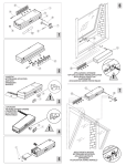
a. With a pencil, mark the midline of the window. Apply the self-adhesive drilling template (fig.
1-9) to the window and drill the holes using a drill and drill bits with a diameter corresponding
to the template.
b. Remove the self-adhesive drilling template and fit the bracket (5-4 and 6-A) and the support
(fig. 5-2 and 6-2) to the window and the frame respectively, using the screws supplied. (N.B.:
the screws are ideal for aluminium windows. For wood applications, use diameter 4.8 wood
screws with a length suitable for the thickness of the wood - fig. 1-5).
c. The actuator (fig. 1-1) is supplied with a travel of 300 mm and can be adjusted as follows:
Adjusting the travel using a cam
To modify the travel of the actuator chain, connect the actuator to the mains (see point 3)
or use the actuator test cable and then:
1. Power up the actuator.
2. Extract the chain by a length A equal to the travel required, as indicated in Table A.
3. Remove the cover (see fig. 2-1 and 3-1)
4. Fit the travel setting fitting (see fig. 2-2 and 3-2). Example: with chain A=0, the travel
is 90 mm.
5. Refit the cover.
Note: For bottom-hung applications, adjust the travel before fitting the actuator.
d. Fit the actuator to the bracket. Close the window, applying a light pressure to guarantee that
the gaskets are sealed. Then screw in the chain front pin and adjust the position at the bracket.
e. Secure the actuator with the split pin (fig. 1-6). Ensure that the actuator reaches the limit
switch positions correctly without being obstructed. (NB. The actuator is supplied with limit
switch in the closed position).
Standard supply
Every PUSH-CA 30 package contains the following (fig. 1):
1. 1 Actuator
2. 1 Actuator fixing support
3. 1 Front pin for chain
4. 1 Bracket for top-hung outward opening windows
5. 6 4.8x13 UNI 6954 self-tapping screws
6. 1 Split pin
7. 1 Cable clamp
8. 1 Securing pin
9. 1 Drilling template
10. 1 Travel adjustment fitting
1 Instructions booklet
Check that all the components are present and undamaged.
Technical data
THRUST FORCE
150N
CURRENT
DRIVE FORCE
300N
FREQUENCY
50 Hz
THERMAL PROTECTION
100°C
ADJUSTABLE TRAVEL
from 90 to 300 mm
0.8 A ac
OPERATING SPEED
40mm/sec.
CAPACITOR
4 µF
FRONT ADJUSTMENT
Max 10 mm
BUILT-IN RELAY
YES
REMOVABLE TERMINAL
BOARD
YES
PROTECTION RATING
IP 20
PARALLEL CONNECTION
YES
SINGLE-PHASE POWER
SUPPLY
230 V ac
CONSUMPTION
3
150 W
Electrical connection
Warning: injury or death - electrocution hazard.
Disconnect the power supply to the actuators before connecting the actuators or the system
Warning: There must always be a multi-polar mains switch with a minimum contact opening
of 3 mm and a differential of 0.030 A upstream of the actuator control line.
Check the cross-section of the power supply cable: it must have adequate dimensions for
the absorption of the actuator.
Unscrew the two screws indicated in fig. 7-1.
The electrical connections are indicated in fig. 9.
The electrical system must comply with current standards.
N.B.: To ensure the system is safe, use a spring return push-button (dead man) or a power supply
which is timed for the time required for movement.
4
Maintenance
Once a year, check that the hinges are in good condition, check that the actuator is firmly
secured to the window and check the general condition of the window.
For perfect functioning, lubricate the chain with silicon grease spray.
Change worn parts.
At least every 12 months, test the product to ensure the system is functioning correctly;
for special systems, this check should be done at least every 6 months.
N.B. Maintenance operations must be carried out by specialised personnel
Recommendations and safety standards:
Warnings:
-
-
-
-
-
-
- Check that the window components used allow the actuator to open fully. If not, the parts
subject to stress or the actuator itself may be damaged.
- Attach a “BEWARE MOVING PARTS” adhesive label near the frame.
- Crushing or trapping hazard! The actuator has a drive and thrust force of 300N/150N. The
hardware and the fittings for the accessories must be able to support these loads.
- The window must have suitable support and safety systems; the actuator cannot be considered
as a support or safety device for the window.
- Do NOT touch the chain when it is moving.
- Keep outside the range of the window’s movements when it is operating.
- The window must be fitted with safety arms which are suitable for the weight of the window.
- Disconnect the electrical power supply when installing, adjusting and repairing the actuator.
RIB products must be installed by specialised personnel with suitable technical skills.
Perform the operations as specified by the manufacturer.
The installer must check the installation and the correct functioning of the device.
Do NOT use the product for purposes other than those specified.
Use original spare parts.
Use the deadman command if the window is less than 2.5 m from floor level.