1
21
37
80
66
14
STANDARD CONTROL GEARS / EQUIPOS ESTANDAR
Model
Modelo
Ref.
No.
Output power
range
Output
current
Output voltage
range
Power
factor
System
GHſEKGPE[
Max.temp.
CVVERQKPV
1RGTCVKPI
temp.
Rango de potencia
en módulo
Corriente
de salida
Rango de tensión
de salida
Factor de
potencia
Rendimiento
del sistema
Temp.máx.
envolvente
Temp.
funcionamiento
Homologaciones
DC/AC 50-60Hz
Constant current control gears for LED modules up to 10 W. IP20
Equipos de alimentación de corriente constante para módulos de LED
hasta 10 W. IP20
Approvals
LC-B DLC-B
220-240V
W
mA
Vdc
NJ
dž
tc (°C)
ta (°C)
LC 102/350-B
9918026
1... 2
350
3... 7
0,73
75
75
-25… +55
01
LC 103/500-B
9918027
1... 3
500
3... 7
0,83
75
75
-25… +55
01
LC 104/700-B
9918028
1... 4
700
3... 7
0,90
75
80
-25… +55
01
LC 110/350-B
9918021
3... 10
350
9... 31
0,97
80
75
-25... +50
01
LC 110/500-B
9918022
4... 10,5
500
9... 21
0,97
80
80
-25... +50
01
LC 110/700-B
9918023
4... 10
700
6... 16
0,98
80
75
-25... +50
01
LC 109/1050-B
9918024
3... 9
1050
3... 9
0,96
80
75
-25... +50
01
DIMMABLE CONTROL GEARS / EQUIPOS REGULABLES
DLC 108/200-B
9918035
4... 8
200
20... 39
0,94
80
80
-25... +50
01
DLC 111/300-B
9918036
7... 11
300
25... 38
0,96
80
85
-25... +50
01
DLC 110/350-B
9918031
3... 10
350
9... 31
0,97
80
75
-25... +50
01
DLC 110/500-B
9918032
4... 10,5
500
9... 21
0,97
80
85
-25... +50
01
DLC 110/700-B
9918033
4... 10
700
6... 16
0,98
80
80
-25... +50
01
DLC 109/1050-B
9918034
3... 9
1050
3... 9
0,96
80
80
-25... +50
01
~ IP20 equipment.
~ Class II electrical protection.
~ Indoor use.
~ Equipped with terminal cover and cable clamps system.
~ Maximum length of secondary wire: 5 m.
~ Suitable for installation on wooden surfaces.
~ High power factor.
~ Overload protection.
~ Short circuit protection.
~ Protection against no load operation.
~ Withstands 2 hours at 350V (AC).
~ Permitted input voltage AC/DC: 198-264V.
~ Allowed dimmers for DLC models:
Trailing-edge and leading-edge dimming.
Dimming 5% - 100%.
~ Nominal lifetime at max. ta allowed: 50.000h (with a failure rate
max.0,2% per 1000h).
~ Equipos IP20.
~ Protección eléctrica Clase II.
~ Uso interior.
~ Equipados con cubre-clemas y sistema de prensa-cables.
~ Longitud máxima de los cables del secundario: 5 m.
~ Aptos para montaje sobre madera.
~ Alto factor de potencia.
~ Protección contra sobrecarga.
~ Protección contra cortocircuitos.
~ Protección en circuito abierto.
~ Soporta 2 horas a 350V (AC).
~ Tensión permitida AC/DC: 198-264V.
~ Tipo de regulador que admite los modelos DLC:
%QTVGCNſPCNFGNCHCUG[EQTVGCNRTKPEKRKQFGNCHCUG
Regulación 5% - 100%.
~ Vida útil a máxima ta permitida: 50.000h (tasa de fallo max. 0,2%
por 1000h).
Packaging and weight on www.elt.es/productos/packaging_ELT.pdf
2TQFWEVUGNGEVKQPQPYYYGNVGURTQFWEVQURTQFWEVAſPFGTJVON
Instructions manual on www.elt.es/productos/inst_manual.html
Recommended dimmers list on:
http://www.elt.es/productos/combinaciones/com_dimmers_DLC_B.pdf
Embalaje y peso en www.elt.es/productos/embalaje_ELT.pdf
Selección de producto en www.elt.es/productos/buscador_producto.html
Manual de instrucciones en www.elt.es/productos/manual_instrucciones.html
Lista de reguladores recomendados en:
http://www.elt.es/productos/combinaciones/com_dimmers_DLC_B.pdf
M
M
LC-B
EN-61347-2-13 Safety / Seguridad
EN-62384 Perfomance / Funcionamiento
EN-61000-3-2 Harmonics / Armónicos
EN-61000-3-3 EMC Emission / CEM
EN-55015 Interferences / Interferencias
EN-61547 EMC Immunity / Inmunidad CEM
DLC-B
Dimmer
2
www.elt.es
Constant current control gears for LED modules up to 16 and 25W.
IP20
Equipos de alimentación de corriente constante para módulos de LED
hasta 16 y 25 W. IP20
29
38
3,6
122
Modelo
Ref.
No.
Output
current
Rango de Corriente
potencia de salida
en módulo
Output
Output
voltage
voltage
range at 240V range at 110V
Rango de
tensión de
salida a 240V
Rango de
tensión de
salida a 110V
Vdc
Power
factor
System
GHſEKGPE[
Max.temp.
CVVERQKPV
1RGTCVKPI
temp.
Factor
Rendimiento Temp.máx.
Temp.
de
del sistema envolvente funcionamiento
potencia
Approvals
Model
Output
power
range
Homologaciones
131
W
mA
Vdc
NJ
dž
tc (°C)
ta (°C)
LC 116/350-A
9918010
4,2... 16
350
12...46
0,85
>85
85
-25...+55
01
LC 116/500-A
9918011
5... 16
500
10...32
0,85
>85
85
-25...+55
01
LC 116/700-A
9918012
4,2... 16
700
6...23
0,84
>85
75
-25...+50
LC 125/300-A
9918009
4,2... 25
300
14… 84
0,90
>85
85
-25... +55
(2)
LC 125/350-A
9918015
3,5... 25
350
10...72
15... 61
0,90
>85
85
-25...+55
(2)
LC 125/500-A
9918016
5... 25
500
10...50
12... 37
0,89
>85
85
-25...+65
LC 125/600-A
9918014
11,4... 25
600
19...42
0,90
>85
75
-25...+50
LC 125/700-A
9918019
14,8... 25
700
21...36
0,90
>85
75
-25...+50
01
01
01
01
~ IP20 equipment.
~ Class II electrical protection.
~ Indoor use.
~ Equipped with terminal cover and cable clamps.
~ Clamping screws on primary and secondary circuits for cables with
diameter: 3 mm to 8 mm.
~ Max. terminal section area 2,5 mm². (secondary circuit).
~ Maximum length of secondary cables: 5 m.
~ Suitable for installation on wooden surfaces.
~ Standby ecological mode: <0,4 W.
~ High power factor.
~ Thermal protection.
~ Overload protection.
~ Short circuit protection
~ Protection against no load operation.
~ LED module dynamic protection.
~ Permitted input voltage AC/DC: 198-264V.
~ Nominal lifetime at max. ta allowed: 50.000h (with a failure rate
max.0,2% per 1000h).
~ Output ripple current < 5%.
~ Equipos IP20.
~ Protección eléctrica Clase II.
~ Uso interiores.
~ Equipados con cubre-clemas y prensa-cables.
~ Cierra cables primario y secundario para conductores entre 3 y
8 mm. de diámetro.
~ Sección máxima en clemas del secundario: 2,5 mm².
~ Longitud máxima de los cables del secundario: 5 m.
~ Aptos para montaje sobre madera.
~ Modo ecológico de standby: consumo <0,4 W.
~ Alto factor de potencia.
~ Protección térmica.
~ Protección contra sobrecarga.
~ Protección contra cortocircuitos.
~ Protección en circuito abierto.
~ Protección dinámica del módulo de LED.
~ Tensión permitida AC/DC: 198-264V.
~ Vida útil a máxima ta permitida: 50.000h (tasa de fallo max. 0,2%
por 1000h).
~ Rizado de corriente de salida < 5%.
(1) Except LC 125/350-A and LC 125/500-A.
(2) 110-240V - Permitted input voltage AC/DC: 99-264V.
(1) Excepto LC 125/350-A y LC 125/500-A.
(2) 110-240V - Tensión permitida AC/DC: 99-264V.
Packaging and weight on www.elt.es/productos/packaging_ELT.pdf
2TQFWEVUGNGEVKQPQPYYYGNVGURTQFWEVQURTQFWEVAſPFGTJVON
Instructions manual on www.elt.es/productos/inst_manual.html
Embalaje y peso en www.elt.es/productos/embalaje_ELT.pdf
Selección de producto en www.elt.es/productos/buscador_producto.html
Manual de instrucciones en www.elt.es/productos/manual_instrucciones.html
1
110
M
M
OR < 5%
ORC
EN-61347-2-13 Safety / Seguridad
EN-62384 Perfomance / Funcionamiento
EN-61000-3-2 Harmonics / Armónicos
EN-61000-3-3 EMC Emission / CEM
EN-55015 Interferences / Interferencias
EN-61547 EMC Immunity / Inmunidad CEM
www.elt.es
LED
MODULES
3
LC-A
220-240V
DC/AC 50-60Hz
LC-A-UN
110-277V
DC/AC 50-60Hz
Constant current control gears for LED modules up to 25W.
7PKXGTUCNXQNVCLG8+2
Equipos de alimentación de corriente constante para módulos de LED
hasta 25W. Tensión universal 110-277V. IP20
29
38
3,6
122
131
Output
power
range
Model
Modelo
Ref.
No.
Output
current
Rango de Corriente
potencia en de salida
módulo
Output
voltage
range
Rango de
tensión de
salida
W
mA
Vdc
Power factor
Factor de
potencia
NJ
110V
230V
System
GHſEKGPE[
Max.temp.
CVVERQKPV
1RGTCVKPI
temp.
Approvals
Rendimiento Temp.máx.
Temp.
del sistema envolvente funcionamiento Homologaciones
dž
tc (°C)
ta (°C)
LC 125/350-A-UN
9918261
8... 25
350
23... 72
0,99
0,94
>85
80
-20...+50
*
01
LC 125/500-A-UN
9918262
8... 25
500
16... 50
0,99
0,94
>85
75
-20...+50
*
01
LC 125/700-A-UN
9918263
8,5… 25
700
12... 36
0,99
0,94
>85
80
-20...+50
*
01
~ IP20 equipment.
~ Class II electrical protection.
~ Indoor use.
~ Equipped with terminal cover and cable clamps.
~ Clamping screws on primary and secondary circuits for cables with
diameter: 3 mm to 8 mm.
~ Max. terminal section area 2,5 mm². (secondary circuit).
~ Maximum length of secondary cables: 5 m.
~ Suitable for installation on wooden surfaces.
~ High power factor.
~ Thermal protection.
~ Overload protection.
~ Short circuit protection
~ Protection against no load operation.
~ Permitted input voltage AC/DC: 99-305V.
~ Nominal lifetime at max. ta allowed: 50.000h (with a failure rate
max.0,2% per 1000h).
*In process
~ Equipos IP20.
~ Protección eléctrica Clase II.
~ Uso interiores.
~ Equipados con cubre-clemas y prensa-cables.
~ Cierra cables primario y secundario para conductores entre 3 y
8 mm. de diámetro.
~ Sección máxima en clemas del secundario: 2,5 mm².
~ Longitud máxima de los cables del secundario: 5 m.
~ Aptos para montaje sobre madera.
~ Alto factor de potencia.
~ Protección térmica.
~ Protección contra sobrecarga.
~ Protección contra cortocircuitos.
~ Protección en circuito abierto.
~ Tensión permitida AC/DC: 99-305V.
~ Vida útil a máxima ta permitida: 50.000h (tasa de fallo max. 0,2%
por 1000h).
*En proceso
Packaging and weight on www.elt.es/productos/packaging_ELT.pdf
2TQFWEVUGNGEVKQPQPYYYGNVGURTQFWEVQURTQFWEVAſPFGTJVON
Instructions manual on www.elt.es/productos/inst_manual.html
Embalaje y peso en www.elt.es/productos/embalaje_ELT.pdf
Selección de producto en www.elt.es/productos/buscador_producto.html
Manual de instrucciones en www.elt.es/productos/manual_instrucciones.html
M
M
EN-61347-2-13 Safety / Seguridad
EN-62384 Perfomance / Funcionamiento
EN-61000-3-2 Harmonics / Armónicos
EN-61000-3-3 EMC Emission / CEM
EN-55015 Interferences / Interferencias
EN-61547 EMC Immunity / Inmunidad CEM
LED
MODULES
4
www.elt.es
&KOOCDNGEQPUVCPVEWTTGPVEQPVTQNIGCTUHQT.'&OQFWNGUWRVQ
and 25 W. IP20
Equipos regulables de alimentación de corriente constante
para módulos de LED hasta 16 y 25 W. IP20
DLC-A
220-240V
50-60Hz
29
38
3,6
122
Modelo
Ref.
No.
Output
current
Output voltage
range
Power
factor
System
GHſEKGPE[
Rango de potencia
en módulo
Corriente
de salida
Rango de
tensión de salida
Factor de
potencia
Rendimiento
del sistema
Max.temp.
CVVERQKPV
1RGTCVKPI
temp.
Temp.máx.
Temp.
envolvente funcionamiento
Homologaciones
Model
Output power
range
Approvals
131
W
mA
Vdc
NJ
dž
tc (°C)
ta (°C)
DLC 116/350-A
9918232
10… 16
350
29… 46
0,85
85
75
-25… +50
*
01
DLC 116/500-A
9918233
10… 16
500
20... 32
0,85
85
85
-25… +50
*
01
DLC 116/700-A
9918236
10… 16
700
14... 23
0,85
85
75
-25… +50
*
01
DLC 120/1050-A
9918247
10… 20
1050
10... 19
0,92
85
80
-25… +50
*
01
DLC 125/350-A
9918252
16… 25
350
45… 72
0,93
85
75
-25… +50
*
01
DLC 125/500-A
9918253
16… 25
500
32… 50
0,96
85
85
-25… +50
*
01
DLC 125/700-A
9918256
16… 25
700
23... 37
0,94
85
80
-25… +50
*
01
~ IP20 equipment.
~ Class II electrical protection.
~ Indoor use.
~ Equipped with terminal cover and cable clamps.
~ Clamping screws on primary and secondary circuits for cables with
diameter: 3 mm to 8 mm.
~ Max. terminal section area 2,5 mm². (secondary circuit).
~ Maximum length of secondary cables: 5 m.
~ Suitable for installation on wooden surfaces.
~ High power factor.
~ Overload protection.
~ Short circuit protection
~ Protection against no load operation.
~ Permitted input voltage AC/DC: 198-264V.
~ Allowed dimmers for DLC models:
Trailing-edge and leading-edge dimming.
Dimming 5% - 100%.
~ Nominal lifetime at max. ta allowed: 50.000h (with a failure rate
max.0,2% per 1000h).
*In process
~ Equipos IP20.
~ Protección eléctrica Clase II.
~ Uso interiores.
~ Equipados con cubre-clemas y prensa-cables.
~ Cierra cables primario y secundario para conductores entre 3 y
8 mm. de diámetro.
~ Sección máxima en clemas del secundario: 2,5 mm².
~ Longitud máxima de los cables del secundario: 5 m.
~ Aptos para montaje sobre madera.
~ Alto factor de potencia.
~ Protección contra sobrecarga.
~ Protección contra cortocircuitos.
~ Protección en circuito abierto.
~ Tensión permitida AC/DC: 198-264V.
~ Tipo de regulador que admite los modelos DLC:
%QTVGCNſPCNFGNCHCUG[EQTVGCNRTKPEKRKQFGNCHCUG
Regulación 5% - 100%.
~ Vida útil a máxima ta permitida: 50.000h (tasa de fallo max. 0,2%
por 1000h).
*En proceso
Data into this datasheet are subject to change without prior notice for
the purpose of products improvement. We kindly request you to ask
VJGNCVGUVURGEKſECVKQPU
Los datos de esta hoja de catálogo están sujeto a cambios sin previo
aviso por cuestiones de mejora de producto. Les rogamos reclamen
la documentación más actualizada.
Packaging and weight on www.elt.es/productos/packaging_ELT.pdf
2TQFWEVUGNGEVKQPQPYYYGNVGURTQFWEVQURTQFWEVAſPFGTJVON
Instructions manual on www.elt.es/productos/inst_manual.html
Embalaje y peso en www.elt.es/productos/embalaje_ELT.pdf
Selección de producto en www.elt.es/productos/buscador_producto.html
Manual de instrucciones en www.elt.es/productos/manual_instrucciones.html
M
M
DLC-A
L
EN-61347-2-13 Safety / Seguridad
EN-62384 Perfomance / Funcionamiento
EN-61000-3-2 Harmonics / Armónicos
EN-61000-3-3 EMC Emission / CEM
EN-55015 Interferences / Interferencias
EN-61547 EMC Immunity / Inmunidad CEM
www.elt.es
Dimmer
5
LC-C
220-240V
DC/AC 50-60Hz
Constant current control gears for LED modules up to 60W. IP20
Equipos de alimentación de corriente constante para módulos de LED
hasta 60W. IP20
40
28
4,25
5
5
220
230
Output power
range
Model
Output current
Output voltage
range
Power factor
Factor de
potencia
System
GHſEKGPE[
Max.temp. at
VERQKPV
1RGTCVKPI
temp.
Rendimiento
del sistema
Temp.máx.
envolvente
Temp.
funcionamiento
Ref.
No.
Rango de
potencia en
módulo
Corriente de
salida
W
mA
Vdc
NJ
dž
tc (°C)
ta (°C)
LC 142/600-C
9918042
21... 42
600
35... 70
0,99
87
75
-25... +50
LC 142/650-C
9918043
21... 42
650
32... 65
0,99
87
75
-25... +50
LC 142/700-C
9918044
24... 42
700
34... 60
0,99
87
75
-25... +50
LC 152/600-C
9918045
30... 52
600
50... 86
0,99
87
75
-25... +50
LC 156/650-C
9918046
32... 56
650
50... 86
0,99
87
75
-25... +50
LC 160/700-C
9918040
24... 60
700
34... 86
0,99
87
75
-25... +50
Modelo
Rango de
tensión de
salida
~ IP20 equipment.
~ Driver for built-in use. Class I.
~ Maximum length of secondary cables: 2 m.
~ High power factor.
~ Overload protection.
~ Protection against no load operation.
~ Withstands 2 hours at 350V (AC).
~ Permitted input voltage AC: 198-264V; DC:150-270V.
`4CRKFEQPPGEVQTYKVJſZKPIURTKPI
Conductor size 0,5 - 1,5 mm2.
~ Nominal lifetime at max. ta allowed: 50.000h (with a failure rate
max.0,2% per 1000h).
~ Equipos IP20.
~ Equipo a incorporar. Clase I
~ Longitud máxima de los cables del secundario: 2 m.
~ Alto factor de potencia.
~ Protección contra sobrecarga
~ Protección en circuito abierto.
~ Soporta 2 horas a 350V (AC).
~ Tensión permitida AC: 198-264V; DC: 150-270V.
`%QPGEVQTGUFGEQPGZKÎPT¶RKFCEQPOWGNNGFGſLCEKÎP
.
Sección conductor 0,5 - 1,5 mm2.
~ Vida útil a máxima ta permitida: 50.000h (tasa de fallo max. 0,2%
por 1000h).
Packaging and weight on www.elt.es/productos/packaging_ELT.pdf
2TQFWEVUGNGEVKQPQPYYYGNVGURTQFWEVQURTQFWEVAſPFGTJVON
Instructions manual on www.elt.es/productos/inst_manual.html
Embalaje y peso en www.elt.es/productos/embalaje_ELT.pdf
Selección de producto en www.elt.es/productos/buscador_producto.html
Manual de instrucciones en www.elt.es/productos/manual_instrucciones.html
EN-61347-2-13 Safety / Seguridad
EN-61000-3-2 Harmonics / Armónicos
EN-61000-3-3 EMC Emission / CEM
EN-55015 Interferences / Interferencias
EN-61547 EMC Immunity / Inmunidad CEM
-
LED
MODULES
+
L
N
6
www.elt.es
Constant current control gears for LED modules up to 50W. IP20
Equipos de alimentación de corriente constante para módulos de LED
hasta 50W. IP20
29,5
Ø 4,2
69 63
92,5
108
Model
Output
current
Output voltage
range
Power
factor
System
GHſEKGPE[
Max.temp.
CVVERQKPV
1RGTCVKPI
temp.
Homologaciones
Output
power range
Approvals
STANDARD CONTROL GEARS / EQUIPOS ESTANDAR
Ref.
No.
Rango de
potencia en
módulo
Corriente
de salida
W
mA
Vdc
NJ
dž
tc (°C)
ta (°C)
LC 150/350-E
9918171
23… 50
350
66… 143
0,98
90
75
-20… +50
01
LC 150/500-E
9918172
23… 50
500
46… 100
0,98
90
75
-20… +50
01
LC 150/700-E
9918173
24… 50
700
34… 72
0,98
89
75
-20… +50
01
LC 148/1050-E
9918174
23... 48
1050
22… 46
0,98
87
75
-20… +50
01
LC 142/1400-E
9918175
18… 42
1400
13… 30
0,98
86
75
-20… +50
01
Modelo
Factor de Rendimiento
Rango de
tensión de salida potencia del sistema
Temp.máx.
Temp.
envolvente funcionamiento
CONTROL GEARS WITH FAN OUTPUT / EQUIPOS CON SALIDA PARA VENTILADOR
LC 150/350-E-FAN
9918211
23… 50
350
66… 143
0,98
90
75
-20… +50
01
LC 150/500-E-FAN
9918212
23… 50
500
46… 100
0,98
90
75
-20… +50
01
LC 150/700-E-FAN
9918213
24… 50
700
34… 72
0,98
89
75
-20… +50
01
LC 148/1050-E-FAN
9918214
23… 48
1050
22… 46
0,98
87
75
-20… +50
01
LC 142/1400-E-FAN
9918215
18... 42
1400
13… 30
0,98
86
75
-20… +50
01
~ IP20 equipment.
~ Driver for built-in use. Class I.
~ Maximum length of secondary cables: 2 m.
~ High power factor.
~ Thermal protection.
~ Overload protection.
~ Short circuit protection.
~ Protection against no load operation.
~ Withstands 2 hours at 350V (AC).
~ Permitted input voltage AC/DC 198-264V.
`4CRKFEQPPGEVQTYKVJſZKPIURTKPI
Conductor size 0,5-1,5 mm2.
~ Drivers connection in series.
~ Nominal lifetime at max. ta allowed: 50.000h ( with a failure rate
max. 0,2% per 1000h).
~ (2) Output ripple current <2%.
~ THD <10%.
~ For further currents consult our commercial department.
~ Equipos IP20.
~ Equipo a incorporar. Clase I
~ Longitud máxima de los cables del secundario: 2 m.
~ Alto factor de potencia.
~ Protección térmica.
~ Protección contra sobrecarga
~ Protección contra cortocircuitos.
~ Protección en circuito abierto.
~ Soporta 2 horas a 350V (AC).
~ Tensión permitida AC/DC: 198-264V.
`%QPGEVQTGUFGEQPGZKÎPT¶RKFCEQPOWGNNGFGſLCEKÎP
.
Sección conductor 0,5-1,5 mm2.
~ Conexión de equipos en serie.
~ Vida útil a máxima ta permitida: 50.000h (tasa de fallo max. 0,2%
por 1000h).
~ (2) Rizado de corriente de salida <2%.
~ THD <10%.
~ Para otras corrientes consultar con el departamento comercial.
(1) Except LC 150/350-E and LC 148/1050-E.
LC 150/350-E-FAN and LC 148/1050-E-FAN.
(2) Except LC 148/1050-E and LC 148/1050-E-FAN. ORC<4%.
(1) Excepto LC 150/350-E y LC 148/1050-E.
LC 150/350-E-FAN y LC 148/1050-E-FAN.
(2) Excepto LC 1148/1050-E y LC 148/1050-E-FAN. ORC<4%.
Packaging and weight on www.elt.es/productos/packaging_ELT.pdf
2TQFWEVUGNGEVKQPQPYYYGNVGURTQFWEVQURTQFWEVAſPFGTJVON
Instructions manual on www.elt.es/productos/inst_manual.html
Embalaje y peso en www.elt.es/productos/embalaje_ELT.pdf
Selección de producto en www.elt.es/productos/buscador_producto.html
Manual de instrucciones en www.elt.es/productos/manual_instrucciones.html
1
100
M
M
1
2
ORC < 2%
With fan output
Con salida ventilador
EN-61347-2-13 Safety / Seguridad
EN-62384 Perfomance / Funcionamiento
EN-61000-3-2 Harmonics / Armónicos
EN-61000-3-3 EMC Emission / CEM
EN-55015 Interferences / Interferencias
EN-61547 EMC Immunity / Inmunidad CEM
www.elt.es
Standard control gear
Equipo estándar
12 Vdc
Imax150mA
N
OUTPUT
7
L
N
L
LC-E
220-240V
DC/AC 50-60Hz
153,5
32
Ø4
70,2
4,5
2
160,5
170,5
STANDARD CONTROL GEARS / EQUIPOS ESTANDAR
Output
power range
Model
Output
current
Output
voltage range
Power
factor
System
GHſEKGPE[
Max.temp.
CVVERQKPV
1RGTCVKPI
temp.
Homologaciones
DC/AC 50-60Hz
Constant current control gears for LED modules up to 50W.
2TQVGEVKQPENCUU++CPFKPFGRGPFGPVWUG+2
Equipos de alimentación de corriente constante para módulos de LED
hasta 50W. Clase II y uso independiente. IP20
Approvals
LC-E-C2
220-240V
Ref.
No.
Rango de
potencia en
módulo
Corriente
de salida
W
mA
Vdc
NJ
dž
tc (°C)
ta (°C)
LC 150/350-E-C2
9918181
23… 50
350
66… 143
0,98
90
75
-20… +50
01
LC 150/500-E-C2
9918182
23… 50
500
46… 100
0,98
90
75
-20… +50
01
LC 150/700-E-C2
9918183
24… 50
700
34… 72
0,98
89
75
-20… +50
01
LC 150/900-E-C2
9918187
23… 50
900
25… 55
0,98
88
75
-20… +50
01
LC 148/1050-E-C2
9918184
23... 48
1050
22… 46
0,98
87
75
-20… +50
01
LC 142/1400-E-C2
9918185
18… 42
1400
13… 30
0,98
86
75
-20… +50
01
Modelo
Rango de
tensión de
salida
Factor de Rendimiento
potencia del sistema
Temp.máx.
Temp.
envolvente funcionamiento
CONTROL GEARS WITH FAN OUTPUT / EQUIPOS CON SALIDA PARA VENTILADOR
LC 150/350-E-C2-FAN
9918221
23… 50
350
66… 143
0,98
90
75
-20… +50
01
LC 150/500-E-C2-FAN
9918222
23… 50
500
46… 100
0,98
90
75
-20… +50
01
LC 150/700-E-C2-FAN
9918223
24… 50
700
34… 72
0,98
89
75
-20… +50
01
LC 148/1050-E-C2-FAN
9918224
23… 48
1050
22… 46
0,98
87
75
-20… +50
01
LC 142/1400-E-C2-FAN
9918225
18... 42
1400
13… 30
0,98
86
75
-20… +50
01
~ IP20 equipment for independent use. Class II control gear
~ Maximum length of secondary cables: 5 m.
~ High power factor.
~ Thermal protection.
~ Overload protection.
~ Short circuit protection.
~ Protection against no load operation.
~ Withstands 2 hours at 350V (AC).
~ Permitted input voltage AC/DC: 198-264V.
`4CRKFEQPPGEVQTYKVJſZKPIURTKPI
Conductor size 0,5-1,5 mm2.
~ Drivers connection in series.
~ Nominal lifetime at max. ta allowed: 50.000h ( with a failure rate
max. 0,2% per 1000h).
~ (2) Output ripple current <2%.
~ THD <10%.
~ For further currents consult our commercial department.
~ Equipos para uso independiente IP20. Equipos Clase II
~ Longitud máxima de los cables del secundario: 5 m.
~ Alto factor de potencia.
~ Protección térmica.
~ Protección contra sobrecarga.
~ Protección contra cortocircuitos.
~ Protección en circuito abierto.
~ Soporta 2 horas a 350V (AC).
~ Tensión permitida AC/DC: 198-264V.
`%QPGEVQTGUFGEQPGZKÎPT¶RKFCEQPOWGNNGFGſLCEKÎP
.
Sección conductor 0,5-1,5 mm2.
~ Conexión de equipos en serie.
~ Vida útil a máxima ta permitida: 50.000h (tasa de fallo max. 0,2%
por 1000h).
~ (2) Rizado de corriente de salida <2%.
~ THD <10%.
~ Para otras corrientes consultar con el departamento comercial.
(1) Except LC 150/350-E-C2 and LC 148/1050-E-C2.
LC 150/350-E-C2-FAN and LC 148/1050-E-C2-FAN.
(2) Except LC 148/1050-E-C2 and LC 148/1050-E-C2-FAN.
ORC<4%.
(1) Excepto LC 150/350-E-C2 y LC 148/1050-E-C2.
LC 150/350-E-C2-FAN y LC 148/1050-E-C2-FAN.
(2) Excepto LC 1148/1050-E-C2 y LC 148/1050-E-C2-FAN.
ORC<4%.
Packaging and weight on www.elt.es/productos/packaging_ELT.pdf
2TQFWEVUGNGEVKQPQPYYYGNVGURTQFWEVQURTQFWEVAſPFGTJVON
Instructions manual on www.elt.es/productos/inst_manual.html
Embalaje y peso en www.elt.es/productos/embalaje_ELT.pdf
Selección de producto en www.elt.es/productos/buscador_producto.html
Manual de instrucciones en www.elt.es/productos/manual_instrucciones.html
1
100
M
M
1
2
ORC < 2%
EN-61347-2-13 Safety / Seguridad
EN-62384 Perfomance / Funcionamiento
EN-61000-3-2 Harmonics / Armónicos
EN-61000-3-3 EMC Emission / CEM
EN-55015 Interferences / Interferencias
EN-61547 EMC Immunity / Inmunidad CEM
With fan output
Con salida ventilador
Standard control gear
Equipo estándar
12 Vdc
Imax150mA
N
L
N
L
OUTPUT
8
www.elt.es
%QPUVCPVEWTTGPVEQPVTQNIGCTUHQT.'&OQFWNGUWRVQ97PKXGTUCN
voltage 110-277V. IP20
Equipos de alimentación de corriente constante para módulos de LED
hasta 50W. Tensión Universal 110-277V. IP20
29,5
Ø 4,2
69 63
92,5
108
Model
Modelo
Ref. No.
Output
current
Output Power
range
Output voltage
range
Power
factor
System
GHſEKGPE[
Max.temp.
CVVERQKPV
1RGTCVKPI
temp.
Corriente
de salida
Rango de potencia
en módulo
Rango de tensión
de salida
Factor de
potencia
Rendimiento
del sistema
Temp.máx.
envolvente
Temp.
funcionamiento
NJ
dž
tc (°C)
ta (°C)
W
mA
Vdc
110Vac
230Vac
110Vac
230Vac
LC 150/350-E-UN
9918271
350
23 ... 42
23 ... 50
66... 120
66... 143
0,98
91
75
-20...+50
LC 150/500-E-UN
9918272
500
23 ... 42
23 ... 50
46… 84
46... 100
0,98
91
75
-20...+50
LC 150/700-E-UN
9918273
700
24 ... 42
24 ... 50
34… 60
34... 72
0,98
89
75
-20...+50
LC 148/1050-E-UN
9918274
1050
23 ... 42
23 ... 48
22... 40
22... 46
0,98
89
75
-20...+50
LC 142/1400-E-UN
9918275
1400
18 ... 42
18 ... 42
13... 30
13... 30
0,98
85
75
-20...+50
~ IP20 equipment.
~ Driver for built-in use. Class I.
~ Maximum length of secondary cables: 2 m.
~ High power factor.
~ Thermal protection.
~ Overload protection.
~ Short circuit protection.
~ Protection against no load operation.
~ Withstands 2 hours at 350V (AC).
~ Permitted input voltage AC/DC 99-305V.
`4CRKFEQPPGEVQTYKVJſZKPIURTKPI
Conductor size 0,5-1,5 mm2.
~ Drivers connection in series.
~ Nominal lifetime at max. ta allowed: 50.000h ( with a failure rate
max. 0,2% per 1000h).
~ (2) Output ripple current <2%.
~ THD <10%.
~ For further currents consult our commercial department.
~ Equipos IP20.
~ Equipo a incorporar. Clase I
~ Longitud máxima de los cables del secundario: 2 m.
~ Alto factor de potencia.
~ Protección térmica.
~ Protección contra sobrecarga
~ Protección contra cortocircuitos.
~ Protección en circuito abierto.
~ Soporta 2 horas a 350V (AC).
~ Tensión permitida AC/DC: 99-305V.
`%QPGEVQTGUFGEQPGZKÎPT¶RKFCEQPOWGNNGFGſLCEKÎP
.
Sección conductor 0,5-1,5 mm2.
~ Conexión de equipos en serie.
~ Vida útil a máxima ta permitida: 50.000h (tasa de fallo max. 0,2%
por 1000h).
~ (2) Rizado de corriente de salida <2%.
~ THD <10%.
~ Para otras corrientes consultar con el departamento comercial.
(1) Except LC 150/350-E-UN and LC 148/1050-E-UN.
(2) Except LC 148/1050-E-UN and LC 142/1400-E-UN. ORC<3%.
(1) Excepto LC 150/350-E-UN y LC 148/1050-E-UN.
(2) Excepto LC 148/1050-E-UN y LC 142/1400-E-UN. ORC<3%.
Packaging and weight on www.elt.es/productos/packaging_ELT.pdf
2TQFWEVUGNGEVKQPQPYYYGNVGURTQFWEVQURTQFWEVAſPFGTJVON
Instructions manual on www.elt.es/productos/inst_manual.html
Embalaje y peso en www.elt.es/productos/embalaje_ELT.pdf
Selección de producto en www.elt.es/productos/buscador_producto.html
Manual de instrucciones en www.elt.es/productos/manual_instrucciones.html
1
100
M
M
1
2
ORC < 2%
Standard control gear
Equipo estándar
EN-61347-2-13 Safety / Seguridad
EN-62384 Perfomance / Funcionamiento
EN-61000-3-2 Harmonics / Armónicos
EN-61000-3-3 EMC Emission / CEM
EN-55015 Interferences / Interferencias
EN-61547 EMC Immunity / Inmunidad CEM
www.elt.es
N
9
L
LC-E-UN
110-277V
DC/AC 50-60Hz
LC-E-C2-UN
110-277V
DC/AC 50-60Hz
Constant current control gears for LED modules up to 50W.
2TQVGEVKQPENCUU++CPFKPFGRGPFGPVWUG7PKXGTUCNXQNVCIG8
IP20
Equipos de alimentación de corriente constante para módulos de LED
hasta 50W. Clase II y uso independiente. Tensión universal 110-277V.
IP20
153,5
32
Ø4
70,2
4,5
Model
Modelo
2
160,5
170,5
Ref. No.
Output
current
Output Power
range
Output voltage
range
Corriente
de salida
Rango de potencia
en módulo
W
mA
110Vac
Power
factor
Rango de tensión Factor de
potencia
de salida
Vdc
230Vac
110Vac
230Vac
NJ
System
GHſEKGPE[
Max.temp. at
VERQKPV
1RGTCVKPI
temp.
Rendimiento
del sistema
Temp.máx.
envolvente
Temp.
funcionamiento
dž
tc (°C)
ta (°C)
LC 150/350-E-C2-UN
9918281
350
23 ... 42
23 ... 50
66... 120
66... 143
0,98
91
75
-20...+50
LC 150/500-E-C2-UN
9918282
500
23 ... 42
23 ... 50
46… 84
46... 100
0,98
91
75
-20...+50
LC 150/700-E-C2-UN
9918283
700
24 ... 42
24 ... 50
34… 60
34... 72
0,98
89
75
-20...+50
LC 148/1050-E-C2-UN
9918284
1050
23 ... 42
23 ... 48
22... 40
22... 46
0,98
89
75
-20...+50
LC 142/1400-E-C2-UN
9918285
1400
18 ... 42
18 ... 42
13... 30
13... 30
0,98
85
75
-20...+50
~ IP20 equipment for independent use. Class II control gear.
~ Maximum length of secondary cables: 5 m.
~ High power factor.
~ Thermal protection.
~ Overload protection.
~ Short circuit protection.
~ Protection against no load operation.
~ Withstands 2 hours at 350V (AC).
~ Permitted input voltage AC/DC 99-305V.
`4CRKFEQPPGEVQTYKVJſZKPIURTKPI
Conductor size 0,5-1,5 mm2.
~ Drivers connection in series.
~ Nominal lifetime at max. ta allowed: 50.000h ( with a failure rate
max. 0,2% per 1000h).
~ (2) Output ripple current <2%.
~ THD <10%.
~ For further currents consult our commercial department.
~ Equipos para uso independiente IP20. Equipos Clase II.
~ Longitud máxima de los cables del secundario: 5 m.
~ Alto factor de potencia.
~ Protección térmica.
~ Protección contra sobrecarga
~ Protección contra cortocircuitos.
~ Protección en circuito abierto.
~ Soporta 2 horas a 350V (AC).
~ Tensión permitida AC/DC: 99-305V.
`%QPGEVQTGUFGEQPGZKÎPT¶RKFCEQPOWGNNGFGſLCEKÎP
.
Sección conductor 0,5-1,5 mm2.
~ Conexión de equipos en serie.
~ Vida útil a máxima ta permitida: 50.000h (tasa de fallo max. 0,2%
por 1000h).
~ (2) Rizado de corriente de salida <2%.
~ THD <10%.
~ Para otras corrientes consultar con el departamento comercial.
(1) Except LC 150/350-E-C2-UN and LC 148/1050-E-C2-UN.
(2) Except LC 148/1050-E-C2-UN and LC 142/1400-E-C2-UN.
ORC<3%
(1) Excepto LC 150/350-E-C2-UN y LC 148/1050-E-C2-UN.
(2) Excepto LC 148/1050-E-C2-UN y LC 142/1400-E-C2-UN.
ORC<3%.
Packaging and weight on www.elt.es/productos/packaging_ELT.pdf
2TQFWEVUGNGEVKQPQPYYYGNVGURTQFWEVQURTQFWEVAſPFGTJVON
Instructions manual on www.elt.es/productos/inst_manual.html
Embalaje y peso en www.elt.es/productos/embalaje_ELT.pdf
Selección de producto en www.elt.es/productos/buscador_producto.html
Manual de instrucciones en www.elt.es/productos/manual_instrucciones.html
1
100
M
M
1
2
ORC < 2%
Standard control gear
Equipo estándar
EN-61347-2-13 Safety / Seguridad
EN-62384 Perfomance / Funcionamiento
EN-61000-3-2 Harmonics / Armónicos
EN-61000-3-3 EMC Emission / CEM
EN-55015 Interferences / Interferencias
EN-61547 EMC Immunity / Inmunidad CEM
N
10
L
www.elt.es
8&KOOCDNGEQPUVCPVEWTTGPVEQPVTQNIGCTUHQT.'&OQFWNGU
up to 42W. IP20
Equipos 1...10V regulables de alimentación de corriente constante
para módulos de LED hasta 42W. IP20
DLC-E
1...10V
Available soon / Próximamente
29,5
Ø 4,2
69 63
92,5
Model
Output
current
Output voltage
range
Power
factor
System
GHſEKGPE[
Max.temp.
CVVERQKPV
1RGTCVKPI
temp.
Homologaciones
Output
power range
Approvals
108
Ref.
No.
Rango de
potencia en
módulo
Corriente
de salida
W
mA
Vdc
NJ
dž
tc (°C)
ta (°C)
DLC 142/350-E-1…10V
9918331
24…40
350
69...115
0,96
89
75
-20… +50
*
01
DLC 142/500-E-1…10V
9918332
24…40
500
48…80
0,96
89
75
-20… +50
*
01
DLC 142/700-E-1…10V
9918333
24…41,5
700
34…59
0,95
88
75
-20… +50
*
01
DLC 142/1050-E-1…10V
9918334
29…40
1050
27…38
0,97
88
75
-20… +50
*
01
DLC 142/1400-E-1…10V
9918335
31…42
1400
22…30
0,96
85
75
-20… +50
*
01
Modelo
Factor de Rendimiento
Rango de
tensión de salida potencia del sistema
Temp.máx.
Temp.
envolvente funcionamiento
~ IP20 equipment.
~ Current regulation control through 1…10V signal.
~ Regulation range: 10…100%.
~ Driver for built-in use. Class I.
~ Maximum length of secondary cables: 2 m.
~ High power factor.
~ Thermal protection.
~ Overload protection.
~ Short circuit protection.
~ Protection against no load operation.
~ Withstands 2 hours at 350V (AC).
~ Permitted input voltage AC/DC 198-264V.
`4CRKFEQPPGEVQTYKVJſZKPIURTKPI
Conductor size 0,5-1,5 mm2.
~ Drivers connection in series.
~ Nominal lifetime at max. ta allowed: 50.000h ( with a failure rate
max. 0,2% per 1000h).
~ (2) Output ripple current <2%.
~ THD <10%.
~ Available upon request with protection against surge pulses: 4kV
between phases.
~ For further currents consult our commercial department.
~ Equipos IP20.
~ Control de regulación de corriente mediante señal 1…10V.
~ Rango de regulación: 10…100%.
~ Equipo a incorporar. Clase I.
~ Longitud máxima de los cables del secundario: 2 m.
~ Alto factor de potencia.
~ Protección térmica.
~ Protección contra sobrecarga.
~ Protección contra cortocircuitos.
~ Protección en circuito abierto.
~ Soporta 2 horas a 350V (AC).
~ Tensión permitida AC/DC: 198-264V.
`%QPGEVQTGUFGEQPGZKÎPT¶RKFCEQPOWGNNGFGſLCEKÎP
Sección conductor 0,5-1,5 mm2.
~ Conexión de equipos en serie.
~ Vida útil a máxima ta permitida: 50.000h (tasa de fallo max. 0,2%
por 1000h).
~ (2) Rizado de corriente de salida <2%.
~ THD <10%.
~ Disponible bajo demanda con protección contra impulsos de
sobretensión en red: 4kV entre fases.
~ Para otras corrientes consultar con el departamento comercial.
(1) Except DLC 142/350-E-1…10V, DLC 142/1050-E-1…10V
(2) Except DLC 142/500-E-1…10V, DLC 142/1050-E-1…10V.
ORC<3%.
(1) Excepto DLC 142/350-E-1…10V, DLC 142/1050-E-1…10V
(2) Excepto DLC 142/500-E-1…10V, DLC 142/1050-E-1…10V.
ORC<3%.
*In process
* En proceso
Data into this datasheet are subject to change without prior notice for
the purpose of products improvement. We kindly request you to ask
VJGNCVGUVURGEKſECVKQPU
Los datos de esta hoja de catálogo están sujetos a cambios sin
previo aviso por cuestiones de mejora de producto. Les rogamos
reclamen la documentación más actualizada.
1
100
M
M
1
2
ORC < 2%
EN-61347-2-13 Safety / Seguridad
EN-62384 Perfomance / Funcionamiento
EN-61000-3-2 Harmonics / Armónicos
EN-61000-3-3 EMC Emission / CEM
EN-55015 Interferences / Interferencias
EN-61547 EMC Immunity / Inmunidad CEM
www.elt.es
1...10V
11
N
L
8&KOOCDNGEQPUVCPVEWTTGPVEQPVTQNIGCTUHQT.'&OQFWNGU
WRVQ92TQVGEVKQPENCUU++CPFKPFGRGPFGPVWUG+2
Equipos 1...10V regulables de alimentación de corriente constante
para módulos de LED hasta 42W. Clase II y uso independiente. IP20
Available soon / Próximamente
153,5
32
Ø4
70,2
2
160,5
170,5
Output
power range
Model
Output
current
Output voltage
range
Power
factor
System
GHſEKGPE[
Max.temp.
CVVERQKPV
1RGTCVKPI
temp.
Homologaciones
4,5
Approvals
DLC-E-C2
1...10V
Ref.
No.
Rango de
potencia en
módulo
Corriente
de salida
W
mA
Vdc
NJ
dž
tc (°C)
ta (°C)
DLC 142/350-E-C2-1…10V
9918341
24…40
350
69...115
0,96
89
75
-20… +50
*
01
DLC 142/500-E-C2-1…10V
9918342
24…40
500
48…80
0,96
89
75
-20… +50
*
01
DLC 142/700-E-C2-1…10V
9918343
24…41,5
700
34…59
0,95
88
75
-20… +50
*
01
DLC 142/1050-E-C2-1…10V
9918344
29…40
1050
27…38
0,97
88
75
-20… +50
*
01
DLC 142/1400-E-C2-1…10V
9918345
31…42
1400
22…30
0,96
85
75
-20… +50
*
01
Modelo
Factor de Rendimiento
Rango de
tensión de salida potencia del sistema
Temp.máx.
Temp.
envolvente funcionamiento
~ IP20 equipment for independent use. Class II control gear.
~ Current regulation control through 1…10V signal.
~ Regulation range: 10…100%.
~ Maximum length of secondary cables: 5 m.
~ High power factor.
~ Thermal protection.
~ Overload protection.
~ Short circuit protection.
~ Protection against no load operation.
~ Withstands 2 hours at 350V (AC).
~ Permitted input voltage AC/DC: 198-264V.
`4CRKFEQPPGEVQTYKVJſZKPIURTKPI
Conductor size 0,5-1,5 mm2.
~ Drivers connection in series.
~ Nominal lifetime at max. ta allowed: 50.000h ( with a failure rate
max. 0,2% per 1000h).
~ (2) Output ripple current <2%.
~ THD <10%.
~ Available upon request with protection against surge pulses: 4kV
between phases.
~ For further currents consult our commercial department.
~ Equipos para uso independiente IP20. Equipos Clase II
~ Control de regulación de corriente mediante señal 1…10V.
~ Rango de regulación: 10…100%.
~ Longitud máxima de los cables del secundario: 5 m.
~ Alto factor de potencia.
~ Protección térmica.
~ Protección contra sobrecarga.
~ Protección contra cortocircuitos.
~ Protección en circuito abierto.
~ Soporta 2 horas a 350V (AC).
~ Tensión permitida AC/DC: 198-264V.
`%QPGEVQTGUFGEQPGZKÎPT¶RKFCEQPOWGNNGFGſLCEKÎP
.
Sección conductor 0,5-1,5 mm2.
~ Conexión de equipos en serie.
~ Vida útil a máxima ta permitida: 50.000h (tasa de fallo max. 0,2%
por 1000h).
~ (2) Rizado de corriente de salida <2%.
~ THD <10%.
~ Disponible bajo demanda con protección contra impulsos de
sobretensión en red: 4kV entre fases.
~ Para otras corrientes consultar con el departamento comercial.
(1) Except DLC 142/350-E-C2-1…10V, DLC 142/1050-E-C2-1…10V
(2) Except DLC 142/500-E-C2-1…10V, DLC 142/1050-E-C2-1…10V.
ORC<3%.
(1) Excepto DLC 142/350-E-C2-1…10V,
DLC 142/1050-E-C2-1…10V
(2) Excepto DLC 142/500-E-C2-1…10V,
DLC 142/1050-E-C2- 1…10V. ORC<3%.
*In process
* En proceso
Data into this datasheet are subject to change without prior notice for
the purpose of products improvement. We kindly request you to ask
VJGNCVGUVURGEKſECVKQPU
Los datos de esta hoja de catálogo están sujetos a cambios sin
previo aviso por cuestiones de mejora de producto. Les rogamos
reclamen la documentación más actualizada.
1
100
M
M
1
2
ORC < 2%
EN-61347-2-13 Safety / Seguridad
EN-62384 Perfomance / Funcionamiento
EN-61000-3-2 Harmonics / Armónicos
EN-61000-3-3 EMC Emission / CEM
EN-55015 Interferences / Interferencias
EN-61547 EMC Immunity / Inmunidad CEM
1...10V
N
12
L
www.elt.es
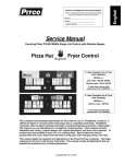
%QPUVCPVOWNVKEWTTGPVEQPVTQNIGCTHQT.'&OQFWNGUWRVQ9+2
Equipo de alimentación multicorriente de corriente constante para
módulos de LED hasta 42W. IP20
LCM-E
29,5
Ø 4,2
69 63
92,5
108
STANDARD CONTROL GEARS / EQUIPOS ESTANDAR
Output power
range
Model
Modelo
LCM 42/350…1050-E
Ref.
No.
Output
current
Rango de
potencia en
módulo
Corriente
de salida
9918311
Output
voltage range
Rango de
tensión de
salida
Power
factor
System
GHſEKGPE[
Factor de Rendimiento
potencia del sistema
W
mA
Vdc
NJ
dž
15,5… 25
350
44… 72
0,92
87
16,5… 34
500
33… 68
0,94
87
21… 42
700
30… 60
0,95
88
27,3… 38
1050
26… 36
0,96
88
Max.temp.
CVVERQKPV
1RGTCVKPI
temp.
Temp.máx.
Temp.
envolvente funcionamiento
tc (°C)
75
ta (°C)
-20… +50
5YKVEJ
RQUKVKQP
* Posición del
interruptor
1
2
3
0
0
0
0
1
0
0
0
1
1
0
0
1
1
1
0
~ 16 output selectable currents by dip-switch.
~ IP20 equipment.
~ Driver for built-in use. Class I.
~ Maximum length of secondary cables: 2 m.
~ High power factor.
~ Thermal protection.
~ Overload protection.
~ Short circuit protection.
~ Protection against no load operation.
~ Withstands 2 hours at 350V (AC).
~ Permitted input voltage AC/DC 198-264V.
`4CRKFEQPPGEVQTYKVJſZKPIURTKPI
Conductor size 0,5-1,5 mm2.
~ Drivers connection in series.
~ Nominal lifetime at max. ta allowed: 50.000h (with a failure rate
max. 0,2% per 1000h).
~ Output ripple current <2%.
~ Low THD.
~ Available upon request with protection against surge pulses: 4kV
between phases.
~ 16 corrientes de salida seleccionables con microswitch.
~ Equipos IP20.
~ Equipo a incorporar. Clase I
~ Longitud máxima de los cables del secundario: 2 m.
~ Alto factor de potencia.
~ Protección térmica.
~ Protección contra sobrecarga
~ Protección contra cortocircuitos.
~ Protección en circuito abierto.
~ Soporta 2 horas a 350V (AC).
~ Tensión permitida AC/DC: 198-264V.
`%QPGEVQTGUFGEQPGZKÎPT¶RKFCEQPOWGNNGFGſLCEKÎP
.
Sección conductor 0,5-1,5 mm2.
~ Conexión de equipos en serie.
~ Vida útil a máxima ta permitida: 50.000h (tasa de fallo max. 0,2%
por 1000h).
~ Rizado de corriente de salida <2%.
~ Bajo THD.
~ Disponible bajo demanda con protección contra impulsos de
sobretensión en red: 4kV entre fases.
* See more combinations on page 15
* Ver más combinaciones en la página 15
100
M
M
ORC < 2%
ON
EN-61347-2-13 Safety / Seguridad
EN-62384 Perfomance / Funcionamiento
EN-61000-3-2 Harmonics / Armónicos
EN-61000-3-3 EMC Emission / CEM
EN-55015 Interferences / Interferencias
EN-61547 EMC Immunity / Inmunidad CEM
www.elt.es
L
OFF
N
1 2 3 4
13
4
LCM-E-C2
%QPUVCPVOWNVKEWTTGPVEQPVTQNIGCTHQT.'&OQFWNGUWRVQ9
2TQVGEVKQPENCUU++CPFKPFGRGPFGPVWUG+2
Equipo de alimentación multicorriente de corriente constante para
módulos de LED hasta 42W. Clase II y uso independiente. IP20
153,5
32
Ø4
70,2
4,5
2
160,5
170,5
STANDARD CONTROL GEARS / EQUIPOS ESTANDAR
Output
power
range
Model
Ref.
No.
Modelo
LCM 42/350…1050-E-C2
9918321
Output
current
Rango de
potencia en
módulo
Corriente
de salida
Output
voltage range
Power
factor
System
GHſEKGPE[
Max.temp.
CVVERQKPV
Factor
Rendimiento Temp.máx.
de
del sistema envolvente
potencia
Rango de
tensión de
salida
W
mA
Vdc
NJ
dž
15,5… 25
350
44… 72
0,92
87
16,5… 34
500
33… 68
0,94
87
21… 42
700
30… 60
0,95
88
27,3… 38
1050
26… 36
0,96
88
1RGTCVKPI
temp.
5YKVEJ
RQUKVKQP
Temp.
funcionamiento
* Posición del
interruptor
tc (°C)
75
ta (°C)
-20… +50
1
2
3
0
0
0
0
1
0
0
0
1
1
0
0
1
1
1
0
~ 16 output selectable currents by dip-switch.
~ IP20 equipment for independent use. Class II control gear
~ Maximum length of secondary cables: 5 m.
~ High power factor.
~ Thermal protection.
~ Overload protection.
~ Short circuit protection.
~ Protection against no load operation.
~ Withstands 2 hours at 350V (AC).
~ Permitted input voltage AC/DC: 198-264V.
`4CRKFEQPPGEVQTYKVJſZKPIURTKPI
Conductor size 0,5-1,5 mm2.
~ Drivers connection in series.
~ Nominal lifetime at max. ta allowed: 50.000h ( with a failure rate
max. 0,2% per 1000h).
~ Output ripple current <2%.
~ THD <10%.
~ Available upon request with protection against surge pulses: 4kV
between phases.
~ For further currents consult our commercial department.
~ 16 corrientes de salida seleccionables con microswitch.
~ Equipos para uso independiente IP20. Equipos Clase II
~ Longitud máxima de los cables del secundario: 5 m.
~ Alto factor de potencia.
~ Protección térmica.
~ Protección contra sobrecarga.
~ Protección contra cortocircuitos.
~ Protección en circuito abierto.
~ Soporta 2 horas a 350V (AC).
~ Tensión permitida AC/DC: 198-264V.
`%QPGEVQTGUFGEQPGZKÎPT¶RKFCEQPOWGNNGFGſLCEKÎP
.
Sección conductor 0,5-1,5 mm2.
~ Conexión de equipos en serie.
~ Vida útil a máxima ta permitida: 50.000h (tasa de fallo max. 0,2%
por 1000h).
~ Rizado de corriente de salida <2%.
~ THD <10%.
~ Disponible bajo demanda con protección contra impulsos de
sobretensión en red: 4kV entre fases.
~ Para otras corrientes consultar con el departamento comercial.
* See more combinations on page 15
* Ver más combinaciones en la pagina 15
100
M
M
4
ORC < 2%
EN-61347-2-13 Safety / Seguridad
EN-62384 Perfomance / Funcionamiento
EN-61000-3-2 Harmonics / Armónicos
EN-61000-3-3 EMC Emission / CEM
EN-55015 Interferences / Interferencias
EN-61547 EMC Immunity / Inmunidad CEM
N
14
L
www.elt.es
%QPUVCPVOWNVKEWTTGPVEQPVTQNIGCTHQT.'&OQFWNGUWRVQ9+2
Equipo de alimentación multicorriente de corriente constante para
módulos de LED hasta 42W. IP20
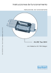
CURRENTS COMBINATION CHART
TABLA DE COMBINACION DE CORRIENTES
5YKVEJRQUKVKQP
Iout
Posición del interruptor
Vout
Wout
1
2
3
4
(mA)
(V)
(W)
0
0
0
0
350
44…72
15,5…25
0
0
0
1
400
36…70
14…28
1
0
0
0
500
33…68
16,5…34
1
0
0
1
550
33…66
18…36
0
1
0
0
580
33…66
19…38
0
1
0
1
630
32…64
20…40
1
1
0
0
700
30…60
21…42
0
0
1
0
750
30…54
22,5…41
1
1
0
1
755
30…54
22,5…41
0
0
1
1
800
29…50
23…40
1
0
1
0
870
28…44
24…39
1
0
1
1
920
28…42
25,5…39
0
1
1
0
950
28…40
26,5…38
0
1
1
1
1000
27…39
27…39
1
1
1
0
1050
26…36
27,5…38
1
1
1
1
1100
26…30
28,5…33
ON
OFF
1 2 3 4
Voltage (V) / Voltaje (V)
LCM DRIVER OPERATION
ÁREA DE OPERACIÓN DEL DRIVER LCM
80
75
70
65
60
55
50
45
40
35
30
25
20
15
10
5
0
350 400 500 550 580 630 700 750 755 800 870 920 950 1000 1050 1100
Current (mA) / Corriente (mA)
The colored space is the operation area. If the operating point is within that range,
the driver can be used.
.CUWRGTſEKGEQNQTGCFCGUGN¶TGCFGQRGTCEKÎPFGNFTKXGT5KGNRWPVQFGVTCDCLQ
se encuentra dentro del área coloreada, el driver será apto para su utilización.
www.elt.es
15
LCM-E
LCM-E-C2
LC-D
220-240V
DC/AC 50-60Hz
Constant current control gears for LED modules up to 90W. IP20
Equipos de alimentación de corriente constante para módulos de LED
hasta 90W. IP20
5
348
7
30
21
4,5
10
4,25
5
5
350
360
Output
power range
Model
Output
current
Output
voltage range
Power
factor
System
GHſEKGPE[
Max.temp.
CVVERQKPV
1RGTCVKPI
temp.
Approvals
Temp.máx.
Temp.
envolvente funcionamiento Homologaciones
Ref.
No.
Rango de
potencia en
módulo
Corriente
de salida
W
mA
Vdc
NJ
dž
tc (°C)
ta (°C)
LC 150/350-D
9918103
23… 50
350
66… 143
0,98
90
75
-20… +55
01
LC 150/500-D
9918105
23… 50
500
46… 100
0,98
90
75
-20… +55
01
LC 142/700-D
9918102
24... 42
700
34... 60
0,98
89
75
-20… +55
01
LC 150/700-D
9918107
24… 50
700
34… 72
0,98
89
75
-20… +55
01
LC 148/1050-D
9918109
23… 48
1050
22… 46
0,98
87
75
-20… +50
01
LC 190/700-D
9918117
40… 90
700
58… 129
0,98
91
75
-20… +50
01
Modelo
Rango de
tensión de
salida
Factor de Rendimiento
potencia del sistema
~ IP20 equipment.
~ Driver for built-in use. Class I.
~ Maximum length of secondary cables: 2 m.
~ High power factor.
~ Overload protection.
~ Short circuit protection.
~ Protection against no load operation.
~ Withstands 2 hours at 350V (AC).
~ Permitted input voltage AC/DC: 198-264V.
`4CRKFEQPPGEVQTYKVJſZKPIURTKPI
Conductor size 0,5-1,5 mm2.
~ Nominal lifetime at max. ta allowed: 50.000h ( with a failure rate
max. 0,2% per 1000h).
~ (2) Output ripple current <2%.
~ THD <10%.
~ For further currents consult our commercial department.
~ Equipos IP20.
~ Equipo a incorporar. Clase I
~ Longitud máxima de los cables del secundario: 2 m.
~ Alto factor de potencia.
~ Protección contra sobrecarga
~ Protección contra cortocircuitos.
~ Protección en circuito abierto.
~ Soporta 2 horas a 350V (AC).
~ Tensión permitida AC/DC: 198-264V.
`%QPGEVQTGUFGEQPGZKÎPT¶RKFCEQPOWGNNGFGſLCEKÎP
.
Sección conductor 0,5-1,5 mm2.
~ Vida útil a máxima ta permitida: 50.000h (tasa de fallo max. 0,2%
por 1000h).
~ (2) Rizado de corriente de salida <2%.
~ THD <10%.
~ Para otras corrientes consultar con el departamento comercial.
(1) Except: LC 148/1050-D, LC 150/350-D and LC 190/700-D.
(2) Except: LC 148/1050-D. ORC<4%.
(1) Excepto: LC 148/1050-D, LC 150/350-D y LC 190/700-D.
(2) Excepto: LC 148/1050-D. ORC<4%.
Packaging and weight on www.elt.es/productos/packaging_ELT.pdf
2TQFWEVUGNGEVKQPQPYYYGNVGURTQFWEVQURTQFWEVAſPFGTJVON
Instructions manual on www.elt.es/productos/inst_manual.html
Embalaje y peso en www.elt.es/productos/embalaje_ELT.pdf
Selección de producto en www.elt.es/productos/buscador_producto.html
Manual de instrucciones en www.elt.es/productos/manual_instrucciones.html
1
1
2
ORC < 2%
EN-61347-2-13 Safety / Seguridad
EN-62384 Perfomance / Funcionamiento
EN-61000-3-2 Harmonics / Armónicos
EN-61000-3-3 EMC Emission / CEM
EN-55015 Interferences / Interferencias
EN-61547 EMC Immunity / Inmunidad CEM
16
www.elt.es
%QPUVCPVEWTTGPVEQPVTQNIGCTUHQT.'&OQFWNGUWRVQ97PKXGTUCN
voltage 110-277V. IP20
Equipos de alimentación de corriente constante para módulos de LED
hasta 50W. Tensión Universal 110-277V. IP20
5
348
7
30
21
4,5
10
4,25
5
5
350
360
Output
power range
Model
Output
current
Output
voltage range
Factor de
potencia
System
GHſEKGPE[
Max.temp. at
VERQKPV
1RGTCVKPI
temp.
Rendimiento
del sistema
Temp.máx.
envolvente
Temp.
funcionamiento
Ref. No.
Rango de
potencia en
módulo
Corriente de
salida
W
mA
Vdc
NJ
dž
tc (°C)
ta (°C)
LC 150/350-D-UN
9918123
23... 50
350
66... 143
0,98
90
75
-20… +55
LC 150/500-D-UN
9918125
23... 50
500
46... 100
0,98
90
75
-20… +55
LC 150/700-D-UN
9918127
24... 50
700
34... 72
0,98
89
75
-20… +55
LC 148/1050-D-UN
9918129
23... 48
1050
22... 46
0,98
87
75
-20… +50
Modelo
Rango de
tensión de
salida
Power factor
~ IP20 equipment.
~ Driver for built-in use. Class I.
~ Maximum length of secondary cables: 2 m.
~ High power factor.
~ Overload protection.
~ Short circuit protection.
~ Protection against no load operation.
~ Withstands 2 hours at 350V (AC).
~ Permitted input voltage AC/DC: 99-305V.
`4CRKFEQPPGEVQTYKVJſZKPIURTKPI
Conductor size 0,5-1,5 mm2.
~ Nominal lifetime at max. ta allowed: 50.000h ( with a failure rate
max. 0,2% per 1000h).
~ (2) Output ripple current <3%.
~ THD <10%.
~ For further currents consult our commercial department.
~ Equipos IP20.
~ Equipo a incorporar. Clase I
~ Longitud máxima de los cables del secundario: 2 m.
~ Alto factor de potencia.
~ Protección contra sobrecarga
~ Protección contra cortocircuitos.
~ Protección en circuito abierto.
~ Soporta 2 horas a 350V (AC).
~ Tensión permitida AC/DC: 99-305V.
`%QPGEVQTGUFGEQPGZKÎPT¶RKFCEQPOWGNNGFGſLCEKÎP
.
Sección conductor 0,5-1,5 mm2.
~ Vida útil a máxima ta permitida: 50.000h (tasa de fallo max. 0,2%
por 1000h).
~ (2) Rizado de corriente de salida <3%.
~ THD <10%.
~ Para otras corrientes consultar con el departamento comercial.
(1) Except: LC 148/1050-D-UN and LC 150/350-D-UN.
(2) Except: LC 148/1050-D-UN. ORC<5%.
(1) Excepto: LC 148/1050-D-UN y LC 150/350-D-UN.
(2) Excepto: LC 148/1050-D-UN. ORC<5%.
Packaging and weight on www.elt.es/productos/packaging_ELT.pdf
2TQFWEVUGNGEVKQPQPYYYGNVGURTQFWEVQURTQFWEVAſPFGTJVON
Instructions manual on www.elt.es/productos/inst_manual.html
Embalaje y peso en www.elt.es/productos/embalaje_ELT.pdf
Selección de producto en www.elt.es/productos/buscador_producto.html
Manual de instrucciones en www.elt.es/productos/manual_instrucciones.html
1
1
2
ORC < 2%
EN-61347-2-13 Safety / Seguridad
EN-62384 Perfomance / Funcionamiento
EN-61000-3-2 Harmonics / Armónicos
EN-61000-3-3 EMC Emission / CEM
EN-55015 Interferences / Interferencias
EN-61547 EMC Immunity / Inmunidad CEM
www.elt.es
17
LC-D-UN
110-277V
DC/AC 50-60Hz
&#.+FKOOCDNG%QPUVCPVEWTTGPVEQPVTQNIGCTHQT.'&OQFWNGU
up to 90W
Equipos DALI regulables de alimentación de corriente
constante para módulos de LED hasta 90W
5
348
7
30
21
4,5
10
4,25
5
5
350
Output
power range
Model
Output
current
Output
voltage range
System
GHſEKGPE[
Max.temp.
CVVERQKPV
1RGTCVKPI
temp.
Ref. No.
Rango de
potencia en
módulo
Corriente
de salida
W
mA
Vdc
NJ
dž
tc (°C)
ta (°C)
DLC 150/700-D-DALI
9918137
27… 50
700
39… 72
0,98
89
75
-20… +55
01
DLC 190/700-D-DALI
9918147
45… 90
700
64…129
0,98
91
75
-20… +50
01
Modelo
Rango de
tensión de
salida
Power
factor
Homologaciones
360
Approvals
DLC-D
DALI
220-240V
50-60Hz
Factor de Rendimiento
potencia del sistema
Temp.máx.
Temp.
envolvente funcionamiento
~ IP20 equipment.
~ Dimming control by DALI inerface.
~ Regulation range 3...100%.
~ PWM output dimming.
~ Regulation by Touch Dim.
~ Corridor function.
~ Driver for built-in use. Class I.
~ Maximum length of secondary cables: 2 m.
~ Standby ecological mode: consumption <0,4W
~ Low Total Harmonic Distortions (THD) at maximum power <8%.
~ High power factor.
~ Dynamic thermal protection.
~ Overload protection.
~ Short circuit protection.
~ Protection against no load operation.
~ Withstands 2 hours at 350V (AC).
~ Permitted input voltage AC/DC: 198-264V.
`4CRKFEQPPGEVQTYKVJſZKPIURTKPI
Conductor size 0,5 - 1,5 mm2.
~ Nominal lifetime at max. ta allowed: 50.000h ( with a failure rate
max. 0,2% per 1000h).
~ Output ripple current <2%.
~ Equipos IP20.
~ Control de regulación mediante interfaz DALI.
~ Rango de regulación de 3… 100%.
~ Regulación a la salida por PWM.
~ Control de regulación mediante Touch Dim.
~ Función corridor.
~ Equipo a incorporar. Clase I
~ Longitud máxima de los cables del secundario: 2 m.
~ Modo ecológico de standby: consumo <0,4W.
~ Bajo factor de distorsión armónica (THD) a máxima carga <8%.
~ Alto factor de potencia.
~ Protección térmica dinámica.
~ Protección contra sobrecarga.
~ Protección contra cortocircuitos.
~ Protección en circuito abierto.
~ Soporta 2 horas a 350V (AC).
~ Tensión permitida AC/DC: 198-264V.
`%QPGEVQTGUFGEQPGZKÎPT¶RKFCEQPOWGNNGFGſLCEKÎP
Sección conductor 0,5 - 1,5 mm2.
~ Vida útil a máxima ta permitida: 50.000h (tasa de fallo max. 0,2%
por 1000h).
~ Rizado de corriente de salida <3%.
~ For further currents consult our commercial department.
~ Para otras corrientes consultar con el departamento comercial.
Packaging and weight on www.elt.es/productos/packaging_ELT.pdf
2TQFWEVUGNGEVKQPQPYYYGNVGURTQFWEVQURTQFWEVAſPFGTJVON
Instructions manual on www.elt.es/productos/inst_manual.html
Embalaje y peso en www.elt.es/productos/embalaje_ELT.pdf
Selección de producto en www.elt.es/productos/buscador_producto.html
Manual de instrucciones en www.elt.es/productos/manual_instrucciones.html
DALI
DA
DA
DALI
DA / LS
DA / N
L
N
DAL I
90
PWM Output Dimming
ORC < 2%
EN-61347-2-13 Safety / Seguridad
EN-62384 Perfomance / Funcionamiento
EN-61000-3-2 Harmonics / Armónicos
EN-61000-3-3 EMC Emission / CEM
EN-55015 Interferences / Interferencias
EN-61547 EMC Immunity / Inmunidad CEM
EN 62386-101 DALI General requirements system
EN 62386-102 DALI General requirements control gear
EN 62386-207 DALI Particular requirements for control gear. LED modules
18
CORRIDOR
TOUCH
SENSOR
L N
CORRIDOR
DA / LS
DA / N
L
N
TOUCH
TOUCH
DA / LS
DA / N
L
N
www.elt.es
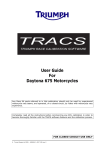
DALI control gear: characteristics and technical information
Equipo DALI: Características e información técnica
Ŗ&KOOCDNGD[&#.+QT6QWEJ&+/HTQOVQQHVJG
TCVGFNWOKPQWUƀWZ
Ŗ4GIWNCDNGRQT&#.+Q617%*&+/EQPTCPIQFGTGIWNCEKÎP
FGNCNFGNƀWLQNWOKPQUQ
TOUCH
DALI
%
Luminous
Flux
100
90
80
70
%
Luminous
Flux
100
90
80
70
60
50
40
30
20
10
0
60
50
40
30
20
10
0
0,0
0,5
1,0
1,5
2,5
2,0
3,0
3,5
4,0
0
50
Time (sec)
100
150
200
250
Digital Light Value
~ &#.+KPVGTHCEGprotected DALI control input against
overvoltage. Polarity free.
~ Interfaz DALI: Los terminales del control DALI están
protegidos frente a sobretensiones. Sin polaridad.
~ 6QWEJ&+/by using standard commercial normally
open switches.
~ TOUCH DIM: Regulación manual con pulsador estándar
(NA: Normalmente abierto).
TOUCH
DALI
L3
L2
L1
N
L1
N
DA / LS
DA / N
Push
button
L
N
LED
MODULES
DLC ...-DALI
DA / LS
DA / N
L N PE DA DA
DALI
controller
DA / LS
DA / N
L
N
L
N
LED
MODULES
DLC ...-DALI
DA / LS
DA / N
L
N
DA / LS
DA / N
L
N
LS
LED
MODULES
DLC ...-DALI
DA / LS
DA / N
L
N
N L1
DA DA
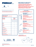
~ %QTTKFQTHWPEVKQP Dimming system that controls light
level when a presence is detected by a conventional
mains on/off sensor connected in DALI input. When the
sensor detects a presence, light level increases up to
100%, otherwise the control gear keeps on providing
10% light level.
DLC ...-DALI
LED
MODULES
DLC ...-DALI
LED
MODULES
DLC ...-DALI
LED
MODULES
N L1 L2 L3
~ Función corridor: sistema para controlar el nivel de luz
con un sensor de movimiento convencional conectado
en los bornes DALI. Cuando el sensor detecta presencia, el nivel de luz aumenta al 100%, en caso contrario,
el equipo mantiene un 10% de nivel de luz.
Ŗ2TQVGEEKQPGU
Protección térmica inteligente de forma que el equipo
TGFWEGGNƀWLQNWOKPQUQCNFGVGEVCTWPGZEGUQFGVGORGTCtura interna.
~ Si la temperatura en Tc sobrepasa 80°C, se reduce la
potencia un 25%.
~ Si la temperatura en Tc baja a 70°C una vez la potencia
se ha reducido en un 25%, el equipo vuelve a funcionamiento normal.
~ Si la temperatura en Tc aumenta hasta 85°C una vez se
ha reducido la potencia un 25%, el equipo pasa a modo
stand-by.
~ Cuando el equipo está en stand-by y la temperatura en
Tc baja a 70°C, el equipo reenciende en funcionamiento
normal.
Ŗ2TQVGEVKQPU
Effective thermal management protection reducing lumiPQWUƀWZYJGPFGVGEVGZEGUUKXGKPVGTPCNVGORGTCVWTG
~ If Tc temperature exceeds 80º C, power is reduced by
25%.
~ If temperature decreases to Tc 70° C once power has
been reduced by 25%, gear returns to normal operation.
~ If Tc temperature increases to 85° C once power has been
reduced by 25%, gear switches to standby mode.
~ When gear is on standby and Tc temperature decreases
to 70° C, gear reboots in normal operation mode.
n
Encendido
Funcionamiento normal
NO
100%
Tc >80°C?
YES/SI
Light level
25% power re
n
Reducción de un 25% de la potencia
Tc >85°C?
Nivel de flujo
luminoso
YES/SI
Stand-by (OFF)
10%
NO
NO
NO
Tc <70°C?
YES/SI
www.elt.es
Tc <70°C?
OFF
YES/SI
19
60 seg.
32 seg.
LC-IP67
220-240V
DC/AC 50-60Hz
Constant current control gears for LED modules IP67 up to 10 W
Equipos de alimentación de corriente constante para módulos de LED
IP67 hasta 10 W
34
67
200
40,5
STANDARD CONTROL GEARS / EQUIPOS ESTANDAR
Output power
range
Model
Output
current
Output
voltage range
Factor de
potencia
System
GHſEKGPE[
Max.temp. at
VERQKPV
1RGTCVKPI
temp.
Rendimiento
del sistema
Temp.máx.
envolvente
Temp.
funcionamiento
Ref. No.
Rango de
potencia en
módulo
Corriente de
salida
W
mA
Vdc
NJ
dž
tc (°C)
ta (°C)
LC 110/350-EN
9916021
3…10
350
9...31
0,97
80
75
-25 .. +50
LC 110/500-EN
9916022
4…10
500
9...21
0,97
80
80
-25 .. +50
LC 110/700-EN
9916023
4…10
700
6...16
0,98
80
75
-25 .. +50
LC 109/1050-EN
9916024
3…9
1050
3...9
0,98
80
75
-25 .. +50
Modelo
Rango de
tensión de
salida
Power factor
DIMMABLE CONTROL GEARS / REGULABLES
DLC 110/350-EN
9916081
3…10
350
9...31
0,97
80
75
-25 .. +50
DLC 110/500-EN
9916082
4…10
500
9...21
0,97
80
85
-25 .. +50
DLC 110/700-EN
9916083
4…10
700
6...16
0,98
80
80
-25 .. +50
DLC 109/1050-EN
9916084
3…9
1050
3...9
0,98
80
80
-25 .. +50
~ Class II electrical protection.
~ Maximum length of secondary wire: 5 m.
~ High power factor.
~ Overload protection.
~ Short circuit protection.
~ Protection against no load operation.
~ Withstands 2 hours at 350V (AC).
~ Permitted input voltage AC/DC: 198-264V.
~ Allowed dimmers for DLC models:
Trailing-edge and leading-edge dimming.
Dimming 5% - 100%.
~ IP67 equipment.
~ Nominal lifetime at max. ta allowed: 50.000h (with a failure rate
max.0,2% per 1000h).
~ Input transient, surge and strike protection device ITP is suitable for
this driver pag. 36 and www.elt.es\productos\pdf\701000000.pdf.
~ ENEC driver inside.
~ Protección eléctrica Clase II.
~ Longitud máxima de los cables del secundario: 5 m.
~ Alto factor de potencia.
~ Protección contra sobrecarga.
~ Protección contra cortocircuitos.
~ Protección en circuito abierto.
~ Soporta 2 horas a 350V (AC).
~ Tensión permitida AC/DC: 198-264V.
~ Tipo de regulador que admite los modelos DLC:
%QTVGCNſPCNFGNCHCUG[EQTVGCNRTKPEKRKQFGNCHCUG
Regulación 5% - 100%.
~ Equipos IP67.
~ Vida útil a máxima ta permitida: 50.000h (tasa de fallo max. 0,2%
por 1000h).
~ Equipo compatible con el sistema de protección contra rayos e
impulsos en la entrada ITP pág. 36 y
www.elt.es\productos pdf\701000000.pdf.
~ Incorpora driver ENEC.
Packaging and weight on www.elt.es/productos/packaging_ELT.pdf
2TQFWEVUGNGEVKQPQPYYYGNVGURTQFWEVQURTQFWEVAſPFGTJVON
Instructions manual on www.elt.es/productos/inst_manual.html
Embalaje y peso en www.elt.es/productos/embalaje_ELT.pdf
Selección de producto en www.elt.es/productos/buscador_producto.html
Manual de instrucciones en www.elt.es/productos/manual_instrucciones.html
LC 1...-EN
M
DLC 1...-EN
M
L
Rojo / Red
N
Negro / Black
Rojo / Red
20
Negro / Black
EN-61347-2-13 Safety / Seguridad
EN-62384 Perfomance / Funcionamiento
EN-61000-3-2 Harmonics / Armónicos
EN-61000-3-3 EMC Emission / CEM
EN-55015 Interferences / Interferencias
EN-61547 EMC Immunity / Inmunidad CEM
N
L
Dimmer
www.elt.es
Constant current control gears for LED modules up to 50W.
+25VTGGVNKIJVKPICRRNKECVKQPU
Equipos de alimentación de corriente constante para módulos de LED
hasta 50W. IP20 Aplicaciones de alumbrado público
29,5
Ø 4,2
69 63
92,5
108
Output
power range
Model
Output
current
Output voltage
range
Power
factor
System
GHſEKGPE[
Max.temp. at
VERQKPV
1RGTCVKPI
temp.
Rango de
tensión de salida
Factor de
potencia
Rendimiento
del sistema
Temp.máx.
envolvente
Temp.
funcionamiento
Ref. No.
Rango de
potencia en
módulo
Corriente de
salida
W
mA
Vdc
NJ
dž
tc (°C)
ta (°C)
LC 150/350-E-VDR
9918291
23… 50
350
66… 143
0,98
90
75
-20… +50
LC 150/500-E-VDR
9918292
23… 50
500
46… 100
0,98
90
75
-20… +50
LC 150/700-E-VDR
9918293
24… 50
700
34… 72
0,98
89
75
-20… +50
LC 148/1050-E-VDR
9918294
23... 48
1050
22… 46
0,98
87
75
-20… +50
LC 142/1400-E-VDR
9918295
18… 42
1400
13… 30
0,98
86
75
-20… +50
Modelo
~ IP20 equipment.
~ Driver for built-in use. Class I.
~ Maximum length of secondary cables: 2 m.
~ High power factor.
~ Thermal protection.
~ Overload protection.
~ Short circuit protection.
~ Protection against no load operation.
~ Enhanced protection against surge pulses: 4Kv between phases.
~ Withstands 2 hours at 350V (AC).
~ Permitted input voltage AC/DC 198-264V.
`4CRKFEQPPGEVQTYKVJſZKPIURTKPI
Conductor size 0,5-1,5 mm2.
~ Drivers connection in series.
~ Nominal lifetime at max. ta allowed: 50.000h ( with a failure rate
max. 0,2% per 1000h).
~ (2) Output ripple current <2%.
~ THD <10%.
~ For further currents consult our commercial department.
~ Available with 12Vdc 150mA FAN output upon request
(LC-E-FAN-VDR).
~ Available in Class II version upon request (LC-E-C2-VDR)
~ Input transient, surge and strike protection device ITP is suitable for
this driver pag. 36 and www.elt.es\productos\pdf\701000000.pdf.
(1) Except LC 150/350-E-VDR and LC 148/1050-E-VDR.
(2) Except LC 148/1050-E-VDR. ORC<4%.
~ Equipos IP20.
~ Equipo a incorporar. Clase I
~ Longitud máxima de los cables del secundario: 2 m.
~ Alto factor de potencia.
~ Protección térmica.
~ Protección contra sobrecarga
~ Protección contra cortocircuitos.
~ Protección en circuito abierto.
~ Protección reforzada contra impulsos de sobretensión en red: 4Kv
entre fases.
~ Soporta 2 horas a 350V (AC).
~ Tensión permitida AC/DC: 198-264V.
`%QPGEVQTGUFGEQPGZKÎPT¶RKFCEQPOWGNNGFGſLCEKÎP
.
Sección conductor 0,5-1,5 mm2.
~ Conexión de equipos en serie.
~ Vida útil a máxima ta permitida: 50.000h (tasa de fallo max. 0,2%
por 1000h).
~ (2) Rizado de corriente de salida <2%.
~ THD <10%.
~ Para otras corrientes consultar con el departamento comercial.
~ Disponible bajo demanda con salida 12Vdc 150mA para ventilador
(LC-E-FAN-VDR).
~ Disponible bajo demanda con envolvente Clase II (LC-E-C2-VDR).
~ Equipo compatible con el sistema de protección contra rayos e
impulsos en la entrada ITP pág. 36 y
www.elt.es\productos\pdf\701000000.pdf.
(1) Excepto LC 150/350-E-VDR y LC 148/1050-E-VDR.
(2) Excepto LC 148/1050-E-VDR. ORC<4%.
Packaging and weight on www.elt.es/productos/packaging_ELT.pdf
2TQFWEVUGNGEVKQPQPYYYGNVGURTQFWEVQURTQFWEVAſPFGTJVON
Instructions manual on www.elt.es/productos/inst_manual.html
Embalaje y peso en www.elt.es/productos/embalaje_ELT.pdf
Selección de producto en www.elt.es/productos/buscador_producto.html
Manual de instrucciones en www.elt.es/productos/manual_instrucciones.html
1
100
M
M
1
EN-61347-2-13 Safety / Seguridad
EN-62384 Perfomance / Funcionamiento
EN-61000-3-2 Harmonics / Armónicos
EN-61000-3-3 EMC Emission / CEM
EN-55015 Interferences / Interferencias
EN-61547 EMC Immunity / Inmunidad CEM
www.elt.es
2
ORC < 2%
4
L-N
4
L-N
N
21
L
LC-E-VDR
220-240V
DC/AC 50-60Hz
LC-XT
220-240V
DC/AC 50-60Hz
Constant current control gears for LED modules up to 150W. IP20
5VTGGVNKIJVKPICRRNKECVKQPU
Equipos de alimentación de corriente constante para módulos de LED
hasta 150W. IP20. Aplicaciones de alumbrado público
38,3
154,4
144,6
78,5 93,4
Model
Modelo
Output
power
range
Ref.
No.
Output
current
Rango de
potencia en
módulo
Corriente
de salida
Output
voltage
range
Rango de
tensión de
salida
Power
factor
System
GHſEKGPE[
Factor de Rendimiento
potencia del sistema
Max.temp.
CVVERQKPV
1RGTCVKPI
temp.
Approvals
Temp.máx.
Temp.
envolvente funcionamiento Homologaciones
W
mA
Vdc
NJ
dž
tc (°C)
ta (°C)
LC 190/350-XT
9916101
50… 90
350
142… 258
0,96
89
75
-40... +60
*
01
LC 190/500-XT
9916102
45… 90
500
90… 180
0,96
89
75
-40... +60
*
01
LC 190/700-XT
9916103
60… 90
700
85… 129
0,96
89
75
-40... +60
*
01
LC 190/1050-XT
9916104
50… 90
1050
48... 86
0,96
89
75
-40... +60
*
01
LC 1150/700-XT
9916113
98… 150
700
140… 215
0,98
91
75
-40… +55
*
01
LC 1150/1050-XT
9916114
95… 150
1050
90,5… 143
0,98
91
75
-40… +55
*
01
LC 1150/1200-XT
9916115
110... 150
1200
91,5... 125
0,98
91
75
-40... +55
*
01
LC 1150/1400-XT
9916116
125… 150
1400
89… 108
0,98
91
75
-40… +55
*
01
~ Built-in-use control gear, protection index IP20.
~ High power factor.
~ Overload protection.
~ Protection against no load operation.
~ Enhanced protection against surge pulses: 6Kv between phases.
`'HſEKGPVRTQVGEVKQPCICKPUV'5&KPVJG.'&OQFWNG
~ Withstands 2 hours at 350V (AC).
~ Permitted input voltage AC/DC: 198-264V.
~ Nominal lifetime at max. ta allowed: 50.000h ( with a failure rate
max. 0,2% per 1000h).
~ Output ripple current <4%.
~ THD <10%.
~ Electronic circuit fully protected against humidity.
~ For further currents, consult our commercial department.
~ Input transient, surge and strike protection device ITP is suitable for
this driver pag. 36 and www.elt.es\productos\pdf\701000000.pdf.
(1) Exclusively LC 190/1050-XT and LC 1150/1400-XT.
~ Equipos a incorporar, indice de proteccón IP20.
~ Alto factor de potencia.
~ Protección contra sobrecarga.
~ Protección en circuito abierto.
~ Protección reforzada contra impulsos de sobretensión en red: 6Kv
entre fases.
~ Protección contra estática en la salida.
~ Soporta 2 horas a 350V (AC).
~ Tensión permitida AC/DC: 198-264V.
~ Vida útil a máxima ta permitida: 50.000h (tasa de fallo max. 0,2%
por 1000h).
~ Rizado de corriente de salida <4%.
~ THD <10%.
~ Circuito electrónico protegido contra la humedad.
~ Para otras corrientes consultar con el departamento comercial.
~ Equipo compatible con el sistema de protección contra rayos
e impulsos en la entrada ITP pág. 36 y (www.elt.es\productos\
pdf\701000000.pdf).
*En proceso
(1) Exclusivamente LC 190/1050-XT y LC 1150/1400-XT.
Data into this datasheet are subject to change without prior notice for
the purpose of products improvement. We kindly request you to ask
VJGNCVGUVURGEKſECVKQPU
Los datos de esta hoja de catálogo están sujetos a cambios sin
previo aviso por cuestiones de mejora de producto. Les rogamos
reclamen la documentación más actualizada.
Packaging and weight on www.elt.es/productos/packaging_ELT.pdf
2TQFWEVUGNGEVKQPQPYYYGNVGURTQFWEVQURTQFWEVAſPFGTJVON
Instructions manual on www.elt.es/productos/inst_manual.html
Embalaje y peso en www.elt.es/productos/embalaje_ELT.pdf
Selección de producto en www.elt.es/productos/buscador_producto.html
Manual de instrucciones en www.elt.es/productos/manual_instrucciones.html
*In process
1
100
M
M
EN-61347-2-13 Safety / Seguridad
EN-62384 Perfomance / Funcionamiento
EN-61000-3-2 Harmonics / Armónicos
EN-61000-3-3 EMC Emission / CEM
EN-55015 Interferences / Interferencias
EN-61547 EMC Immunity / Inmunidad CEM
1
ORC < 4%
6
LED
MODULES
ODP
L-N
ODP
L
mains
N
22
www.elt.es
Emergency lighting kits with self-diagnosis function for 12V to 220V
constant current LED luminaires
Kits para alumbrado de emergencia, con autodiagnóstico,
para luminarias LED de corriente constante de 12V a 220V
21,5
16,8
450
31,5
205,5
210
Ø 23
Ø 4,5
4,8V 1,8 Ah NiCd
1 h.
173
Ø 33
4,8V 4,5 Ah NiCd
250
3 h.
240
250
Approvals
Homologaciones
5GVYGKIJ
Peso conjunto
-+6
'OGTIGPE[WPKVDCVVGT[Unidad de emergencia + bateria)
Ref.
No.
1RGTCVKPI
voltages under
PQTOCNEQPFKVKQPU
Tensión de
funcionamiento en
condiciones normales
LED module not
connected or
FGHGEVKXG
Módulo LED
no conectado o
defectuoso
h
ta (°C)
Kg.
GOGT.'&89J
9953061
min. 12V / max. 50V
max. 60V
4,8V 1,8 Ah NiCd
1
+5... +50
0,420
*
GOGT.'&89J
9953062
min. 12V / max. 50V
max. 60V
4,8V 4,5 Ah NiCd
3
+5... +50
0,730
*
GOGT.'&89J
9953063
min. 30V / max. 220V
max. 250V
4,8V 1,8 Ah NiCd
1
+5... +50
0,420
*
GOGT.'&89J
9953064
min. 30V / max. 220V
max. 250V
4,8V 4,5 Ah NiCd
3
+5... +50
0,730
*
Model
Modelo
0QOKPCN
1RGTCVKPI
Perfomance
temp.
Battery
Funcionamiento
Temp.
KPENWFGF
nominal
funcionamiento
Batería incluída
BATTERIES AND HOLDERS / BATERÍA Y SOPORTE BATERÍA
Model
Modelo
Battery code
Código batería
0QOKPCN2GTHQOCPEG
Funcionamiento nominal
$CVVGT[YGKIJV
Peso batería
Holder code
Código soporte
*QNFGTYGKIJV
Peso soporte
h
Kg.
8#J0K%F
9513041
1
0,200
9331700
0,004
8#J0K%F
9513051
3
0,500
9331701
0,011
~ The emerLED has to be used in combination with a constant current
control gear for LED modules in LED luminaires.
~ Electrical protection: Class I.
~ Protection rating: IP 20.
~ Automatic test according EN 62034.
~ Valid for DIN 0108 / EN 50172 installations.
~ Suitable for cables 0,5-1,5 mm2 section stripping 8 mm.
~ The battery holders are to be ordered separately.
`2QN[XCNGPVGOGTIGPE[NKIJVKPIWPKV5WKVCDNGHQTGXGT[EQPſIWTCVKQP
~ The maximum operating current in the LED module has to be lower
than 2,5A.
`+PECUGQHOCKPUHCKNWTGGOGT.'&WPKVUJCXGCPCFFKVKQPCNſHVJRQNG
to disconnect the mains. So the LED module is completely isolated
from the driver; ensuring its correct re-ignition when it returns to
normal operating mode.
~ Batteries are supplied discharged. For a functional test a 10 minutes
charge period should be enough. To obtain full performance it has
to be connected to the mains at least 48 hours.
~ These emerLED modules include an automatic self-diagnostic
at regular intervals. Every 8 days the correct performance of the
module, the light and the battery is tested. Every 12 weeks the
capacity of the batteries is tested simulating a mains failure and
making a performance test. That is the reason why there’s only
need for a visual and periodical inspection LED display and the
installation.
~ Los emerLED tienen que ser empleados en combinación con un
equipo de alimentación de corriente constante para módulos LED
en las luminarias.
~ Protección eléctrica: Clase I.
~ Grado de protección: IP 20.
~ Autotest de acuerdo a EN 62034.
~ Válido para instalaciones. DIN 0108 / EN 50172.
~ Admite cables de sección 0,5 - 1,5 mm2 con pelado 8 mm.
~ Los soportes para la batería deben solicitarse separadamente.
~ Unidad de iluminación de emergencia polivalente. Válida para
EWCNSWKGTEQPſIWTCEKÎP
~ La corriente máxima de funcionamiento del módulo LED deberá ser
inferior a 2,5A.
~ En el caso de un fallo de red, los equipos de emergencia emerLED
están provistos de un quinto polo para la desconexión de su
alimentación, de forma que el módulo LED se aisla completamente
del driver; asegurando su correcto reencendido cuando regresa a
modo normal de funcionamiento.
~ Las baterías se entregan descargadas. Para una prueba funcional
RWGFGUGTUWſEKGPVGWPVKGORQFGECTICOÈPKOQFGOKPWVQU
Para obtener un rendimiento total deberá estar conectada a la red
eléctrica durante al menos 48 horas.
~ Las unidades emerLED incorporan función de auto-diagnóstico
en intervalos regulares. Cada 8 días ponen a prueba el correcto
funcionamiento del equipo, la luz y la batería. Cada 12 semanas
la capacidad de las baterías se mide mediante la simulación de un
fallo de alimentación, además de la prueba de funcionamiento. De
esta forma sólo es necesaria una inspección visual periódica del
estado del indicador LED y de la instalación.
* En proceso.
* In process.
EN 60598-2-22 Luminaires emergency lighting / Luminarias alumbrado emergencia
EN 61347-1 Safety (general) / Seguridad (general)
EN 61347-2-7 Safety (particular emergency) / Seguridad (particular para emergencias)
www.elt.es
Kg.
23
emerLED
emerLED
emerLED: characteristics and technical information
Características del emerLED e información técnica
LED colour
Status
5KVWCVKQP
Color LED
Estado
Situación
Green
On
Battery charged
Correct functioning
LED
Verde
Encendido
Batería cargada
Funcionamiento correcto
White
Off > 10 mn
Mains failure
Mains below 160V
Battery discharged
Defective FES unit
LED
Blanco
Apagado > 10mn
Fallo de red
Red por debajo de 160V
Bateria descargada
Emergencia defectuosa
Red
Intermittent
ƀCUJKPI
Defective LED module
LED
Rojo
Parpadeo intermitente
Fallo del modulo LED
Red
2GTOCPGPVN[ƀCUJKPI
Defective battery
LED
Rojo
Parpadea
continuamente
Fallo en la bateria
emerLED - LED MODULES
COMBINATIONS
COMBINACIONES
emerLED - MÓDULOS LED
The ideal emerLED will be the one whose output voltage range
includes all operating voltage range of the LED load.
El emerLED idóneo será aquel cuyo rango de tension de
funcionamiento incluya todo el rango de tensión de operación de la
carga.
emerLED VALIDS FOR THE FOLLOWING COMBINATIONS OF eLED MODULES
emerLED VÁLIDOS PARA LAS SIGUIENTES COMBINACIONES DE MÓDULOS eLED
0G.'&EQPPGEVGFKPUGTKGU
eLED Model
Modelo eLED
Nº eLED conectados en serie
1
2
3
4
5
8
10
eLED LINE 1 800
emerLED 12-50V
emerLED 12-50V
emerLED 12-50V
emerLED 30-220V
emerLED 12-50V
emerLED 30-220V
emerLED 30-220V
emerLED 30-220V
eLED LINE 1 1100
emerLED 12-50V
emerLED 12-50V
emerLED 30-220V
emerLED 30-220V
emerLED 30-220V
emerLED 30-220V
emerLED 30-220V
eLED LINE 2 1350
emerLED 12-50V
emerLED 12-50V
emerLED 12-50V
emerLED 30-220V
emerLED 30-220V
emerLED 30-220V
emerLED 30-220V
emerLED 30-220V
eLED LINE 2 1600
emerLED 12-50V
emerLED 12-50V
emerLED 30-220V
emerLED 30-220V
emerLED 30-220V
emerLED 30-220V
emerLED 30-220V
emerLED 30-220V
eLED LINE 2 2100
emerLED 12-50V
emerLED 30-220V
emerLED 30-220V
emerLED 30-220V
emerLED 30-220V
emerLED 30-220V
eLED OCTO 1 1850
emerLED 12-50V
emerLED 30-220V
emerLED 12-50V
emerLED 30-220V
emerLED 30-220V
emerLED 30-220V
emerLED 30-220V
emerLED 30-220V
eLED OCTO 1 2250
emerLED 12-50V
emerLED 30-220V
emerLED 30-220V
emerLED 30-220V
emerLED 30-220V
emerLED 30-220V
eLED SQUARE 2 1700
emerLED 12-50V
emerLED 12-50V
emerLED 30-220V
emerLED 30-220V
emerLED 30-220V
emerLED 30-220V
24
emerLED 30-220V
emerLED 30-220V
www.elt.es
emerLED
emerLED: characteristics and technical information
Características del emerLED e información técnica
% LUMINOUS FLUX IN EMERGENCY
12'4#6+10
CVu%CODKGPVVGOR
% FLUJO LUMINOSO EN EMERGENCIA
(a 25°C temp. ambiente)
The LED current in emergency mode is automatically adjust by the emerLED based on the total voltage of the combination of LED modules connected and the associated battery.
La corriente en modo emergencia es ajustada automáticamente por el emerLED, basandose en la tensión total de la
combinación de módulos LED conectados y la bateria asociada.
Iemergency mode [mA] vs Vout [V] / Imodo emergencia [mA] vs Vsalida [V]
Iemergency mode [mA] / Imodo emergencia [mA]
250
200
150
100
50
0
0
25
50
75
100
125
150
175
200
225
250
Vout [V] / Vsalida [V]
Knowing the total voltage output of the luminaire operating
KPPQTOCNOQFGVJGNWOKPQWUƀWZXCNWGKPGOGTIGPE[OQFG
can be calculated:
1- Locate the value voltage output in normal mode in the
CDQXG ITCRJ VQ ſPF VJG EWTTGPV XCNWG KP GOGTIGPE[
mode.
%CNEWNCVGVJGNWOKPQWUƀWZQWVRWVKPGOGTIGPE[OQFG
with the next equation:
Conociendo la tensión total de salida de la luminaria opeTCPFQGPOQFQPQTOCNUGRWGFGECNEWNCTGNXCNQTFGNƀWLQ
luminoso resultante en modo emergencia:
1- Ubicar el valor de tension de salida en modo normal en
GN ITCſEQ CPVGTKQT RCTC JCNNCT GN XCNQT FG EQTTKGPVG GP
modo emergencia .
%CNEWNCTGNƀWLQNWOKPQUQGPOQFQGOGTIGPEKCEQPNC
siguiente fórmula:
: Luminous flux in emergency mode / Flujo Luminoso en modo emergencia
: Luminous flux in normal mode / Flujo Luminoso en modo normal
: Current in emergency mode / Corriente en modo emergencia
: Current in emergency mode / Corriente en modo normal
All reference values are sensitive to the tolerances of the
LED used
Todos los valores de referencia son sensibles a las tolerancias del LED utilizado
WIRING DIAGRAM
ESQUEMA DE CONEXIONADO
R
R
battery
R
N
emergency unit
1
2
3
4
R
N
L1
L2
L
R
N
L
R
L
R
R
L2
DRIVER
www.elt.es
Mains 230V 50-60Hz
KIT emerLED
LED luminaire / Luminaria LED
25
LED modules eLED LINE 1 800
Módulos LED eLED LINE 1 800
6,1
1,6
2,8
Ø4
18,4
24
15
62,5
62,5
62,5
62,5
15
280
Unidades por caja
7PKVURGTDQZ
Temp. Máx. En la unión
Flujo luminoso
típico a temp.
amb. 25 °C
/CZ6GOR+PVJGLWPEVKQP
Rango de Temp.
tensión de color
típica
Temp. funcionamiento
Intensidad
máxima
6[RKECN
NWOKPQWUƀWZ
CVCODVGOR
25 °C
1RGTCVKPIVGOR
Potencia
típica en
módulo
Colour
temp.
Temp. máx. en tc
Ref.
No.
Modelo
6[RKECN
voltage
range
/CZVGORCVVERQKPV
Model
/CZKOWO
current
CRI
6[RKECN
RQYGTKP
module
~ Módulo de LED apropiado para funcionamiento en corriente
constante.
`#NVCGſEKGPEKCNWOÈPKEC
~ Baja tensión del módulo lo que permite aplicaciones de hasta más
de 4.000lm con una tensión inferior a 50V.
~ Bajo calentamiento del módulo debido al funcionamiento
independiente del LED a baja corriente.
~ Instalación en luminaria.
'ſEKGPEKCNWOKPQUCVÈRKEC
~ LED Module appropriate for operation in constant current.
`*KIJNWOKPQWUGHſEKGPE[
~ Low voltage of the module, allowing applications up to more than
4.000lm with a voltage under 50V.
~ Low heating of the module due to the independent operation of the
LED in low current.
~ Built-in luminaires.
6[RKECNNWOKPQWUGHſECE[
eLED LINE
280mm
800
W
mA
V
*K
*lm
lm / W
tc (°C)
ta (°C)
Tj (°C)
eLED LINE 1 800 830
9950502
6,4
700
8,7... 9,6
3000
750
117
>80
75
-40… +55
110
120
eLED LINE 1 800 840
9950501
6,4
700
8,7... 9,6
4000
800
125
>80
75
-40… +55
110
120
eLED LINE 1 800 857
9950503
6,4
700
8,7... 9,6
5700
820
129
>80
75
-40… +55
110
120
.WOKPQWUƀWZVQNGTCPEGvCPFHQTEQNQWTVGORGTCVWTGvIWCTCPVGGKPICUVCPFCTFFGXKCVKQPQHvRGTOQFWNGG.'&
Tolerancia de Flujo Luminoso de ±7% y de Temperatura de Color ±7% asegurando una desviación típica de un ±3% por módulo eLED
~ Beam angle 120°.
~ Color tolerance: 3 MacAdam’s ellipses - 3SDCM.
~ Excellent thermal performance, not require further dissipation
~ Dimmable.
~ Indifferent installation position.
~ Anti-reverse polarity protection.
~ Designed upon ZHAGA requirements book 7 cat. LLE-L28W2.
~ Push wire connection.
~ The connector allows connection and disconnection.
~ Wire gauge: 0,2... 0,75 mm2.
~ Stripping length: 6... 7 mm.
`.QPINKHGVKOGQHJQWTUCV6ENWOKPQWUƀWZQH CHVGT
this time period.
~ Angulo de visión 120°.
~ Tolerancia de color: 3 elipses de MacAdam - 3SDCM.
~ Bajo calentamiento del módulo, no requiere ningún tipo de
disipación extra.
~ Regulable.
~ Posición de la operación indiferente.
~ Protección contra inversión de polaridad.
~ Diseñado bajo requerimiento ZHAGA libro 7 cat. LLE-L28W2.
~ Conexión mediante conector rápido.
~ Conector que permite conexión y desconexión.
~ Sección conductor: 0,2... 0,75 mm2.
~ Longitud de pelado: 6... 7 mm.
`.CTICXKFCFGJQTCUC6EEQPƀWLQNWOKPQUQ FGURWÃU
de este periodo.
`&KHHWUGTUCXCKNCDNG5GGCEEGUUQTKGUUGEVKQP
~ Difusores disponibles. Ver apartado de accesorios.
~ Made in 5RCKP.
~ 5 years warranty in combination with an appropriate ELT driver.
~ Fabricado en España.
~ Garantía de 5 años en combinación con driver ELT apropiado.
Packaging and weight on www.elt.es/productos/packaging_ELT.pdf
2TQFWEVUGNGEVKQPQPYYYGNVGURTQFWEVQURTQFWEVAſPFGTJVON
Embalaje y peso en www.elt.es/productos/embalaje_ELT.pdf
Selección de producto en www.elt.es/productos/buscador_producto.html
RoHS
EN 62031 Safety / Seguridad
EN 62471 Photo-biological / Fotobiológica
26
www.elt.es
LUMINOUS FLUX DATA
DATOS DEL FLUJO LUMINOSO
Lumenes (lm)
6[RKECNNWOKPQWUƀWZ
CVCODVGORu%
Current
Colour Temperature
Intensidad
Temperatura de Color
Flujo luminoso típico a
temp. amb. 25 °C
mA
*K
*lm
3000
750
4000
800
5700
820
3000
560
4000
600
5700
620
3000
420
4000
450
5700
460
900
800
700
700
500
350
600
3000K
Fila
4000K
Fila
5700K
Fila
500
400
300
200
300
350
400
Corriente (mA)
.WOKPQWUƀWZVQNGTCPEGvCPFHQTEQNQWTVGORGTCVWTGv
IWCTCPVGGKPICUVCPFCTFFGXKCVKQPQHvRGTOQFWNGG.'&
Tolerancia de Flujo Luminoso de ±7% y de Temperatura de Color ±7%
asegurando una desviación típica de un ±3% por módulo eLED
450
500
550
600
650
700
…….. 1050
LED BIN SELECTION
ELECCIÓN DEL BIN DEL LED
Each eLED LINE is made with approved LED and selected
previously during our logistic process, considering brightness, colour and voltage, obtaining guaranteed uniformity
and quality of the light.
$TKIJVPGUU%JQKEGQH.'&UYKVJJKIJGHſEKGPE[VQGPUWTG
NWOGPUYCVVURGEKſGF
8QNVCIG Tolerance in each LED of maximum 0,1V.
%QNQWT The possible variation of LED colour is imperceptible to the human eye, and as a result gives 3
MacAdam’s ellipses: 3SDCM.
Cada eLED LINE se fabrica con LED previamente acordado y seleccionado en nuestro proceso logístico, en cuanto a
Brillo, Color y Tensión, de esta forma la uniformidad y calidad de la luz está garantizada.
Brillo: 'NGEEKÎP FG NQU .'&U EQP CNVQ PKXGN FG GſEKGPEKC
RCTCICTCPVK\CTNQUNÕOGPGUYCVKQGURGEKſECFQU
Tensión: Tolerancia en cada LED máxima de 0,1V.
Color: La posible variación de color de los LED es imperceptible al ojo humano, dando como resultado 3 elipses de
MacAdam: 3SDCM.
LUMINOUS INTENSITY DISTRIBUTION
CURVES (Cd/Klm) @700mA
CURVAS DE DISTRIBUCIÓN DE
INTENSIDAD LUMÍNICA (Cd/Klm) @700mA
This luminous intensity distribution curve is the result of
the information obtained with an unique eLED LINE module
without any type of optics.
Esta curva de distribución de intensidad lumínica es el resultado de los datos obtenidos de un único modulo eLED
LINE sin ningún tipo de óptica.
www.elt.es
27
EXAMPLES OF COMBINATION
eLED LINE AND ELT DRIVER @700mA
R
1 x 1 eLED
~
~
PRI
+
SEC
R
R
DRIVER
EJEMPLOS DE COMBINACIONES
eLED LINE Y DRIVER ELT @700mA
1
Driver LC 110/700-B
280 mm
800 Lm
9,2 Vout
6,4 W
{
~ PRI ~
1 x 2 eLED
+ SEC -
R
R
R
R
DRIVER
R
1
2
{
Driver LC 116/700-A
2 x 280 = 560 mm
2 x 800 = 1.600 Lm
2 x 9,2 = 18,4 Vout
2 x 6,4 = 12,8 W
R
L
N
DRIVER
R
R
R
R
R
1
R
R
2
3
R
4
R
R
5
{
1 x 5 eLED
1
2
R
3
R
R
Driver LC 142/700-C
5 x 280 = 1.400 mm
5 x 800 = 4.000 Lm
5 x 9,2 = 46 Vout
5 x 6,4 = 32 W
4
R
R
R
R
DRIVER
R
R
R
R
5
6
1
2
R
L
N
R
4 x 280 = 1.120 mm
R
R
7
R
R
8
2 x 4 eLED
{
R
R
4 x 2 eLED
R
R
2 x 280 = 560 mm
3
R
4
R
R
R
{
Driver LC 160/700-C
8 x 800 = 6.400 Lm
8 x 9,2 = 73,6 Vout
8 x 6,4 = 51,2 W
R
DRIVER
R
R
R
5
R
R
7
R
L
N
6
R
R
8
2TQFWEVUGNGEVKQPRCICPFYYYGNVGURTQFWEVQURTQFWEVAſPFGTJVON
Selección de producto pág. 51 y www.elt.es/productos/buscador_producto.html
#UUGODN[CPF5CHGV[+PHQTOCVKQP
Información de instalación y de seguridad
The eLED LINE must be applied to dry and clean surfaces
that are free from dust, oil, silicone or other soiling.
'NOÎFWNQFGDGUGTKPUVCNCFQGPUWRGTſEKGUUGECU[NKOpias, libres de polvo, aceite, silicona u otra suciedad.
eLED LINE products are sensitive to mechanical efforts,
avoid applying mechanical tensions, bending stresses, millings, pressure, or any other form of mechanical stress on
them.
Los productos eLED LINE son sensibles a esfuerzos mecánicos, evite aplicar tensiones mecánicas, esfuerzos de
ƀGZKÎPHTGUCFQURTGUKÎPQEWCNSWKGTQVTCHQTOCFGGUVTÃU
mecánico.
eLED LINE modules should be taken by the edges of the
printed circuit board, never by the top side where the LED
components are.
Tome los módulos eLED LINE por los bordes del circuito
impreso, nunca sobre la cara top donde se sitúan los componentes LED.
Handle eLED LINE products in protected zones against
static electricity. (ESD Electric Static Discharge).
Manipule los productos eLED LINE en zonas protegidas
contra la electricidad estática. (ESD Electric Static Discharge).
A gap between consecutive modules is recommended to
facilitate the thermal expansion.
Se recomienda dejar una separación entre módulos consecutivos para favorecer las dilataciones.
0,5 mm
28
www.elt.es
LED modules eLED LINE 1 1100
Módulos LED eLED LINE 1 1100
eLED LINE
280x40mm
1100
6,1
1,6
Ø4
4,4
31,2
40
30
110
30
110
280
Unidades por caja
7PKVURGTDQZ
Temp. Máx. En la unión
Flujo luminoso
típico a temp.
amb. 25 °C
/CZ6GOR+PVJGLWPEVKQP
Temp.
de color
Temp. funcionamiento
Rango
de
tensión
típica
1RGTCVKPIVGOR
Intensidad
máxima
Temp. máx. en tc
Potencia
típica en
módulo
6[RKECN
NWOKPQWUƀWZ
CVCODVGOR
25 °C
/CZVGORCVVERQKPV
Ref.
No.
Colour
temp.
CRI
Modelo
6[RKECN
voltage
range
'ſEKGPEKCNWOKPQUCVÈRKEC
Model
6[RKECN
RQYGTKP /CZKOWO
module
current
~ Módulo de LED apropiado para funcionamiento en corriente
constante.
`#NVCGſEKGPEKCNWOÈPKEC
~ Baja tensión del módulo lo que permite aplicaciones de hasta más
de 4.000lm con una tensión inferior a 50V.
~ Bajo calentamiento del módulo debido al funcionamiento
independiente del LED a baja corriente.
~ Instalación en luminaria.
6[RKECNNWOKPQWUGHſECE[
~ LED Module appropriate for operation in constant current.
`*KIJNWOKPQWUGHſEKGPE[
~ Low voltage of the module, allowing applications up to more than
4.000lm with a voltage under 50V.
~ Low heating of the module due to the independent operation of the
LED in low current.
~ Built-in luminaires.
W
mA
V
*K
*lm
lm / W
tc (°C)
ta (°C)
Tj (°C)
eLED LINE 1 1100 830
9950508
8,5
700
11,6... 12,8
3000
1000
117
>80
75
-40… +55
110
80
eLED LINE 1 1100 840
9950509
8,5
700
11,6... 12,8
4000
1070
125
>80
75
-40… +55
110
80
eLED LINE 1 1100 857
9950510
8,5
700
11,6... 12,8
5700
1100
129
>80
75
-40… +55
110
80
.WOKPQWUƀWZVQNGTCPEGvCPFHQTEQNQWTVGORGTCVWTGvIWCTCPVGGKPICUVCPFCTFFGXKCVKQPQHvRGTOQFWNGG.'&
Tolerancia de Flujo Luminoso de ±7% y de Temperatura de Color ±7% asegurando una desviación típica de un ±3% por módulo eLED
~ Beam angle 120°.
~ Color tolerance: 3 MacAdam’s ellipses - 3SDCM.
~ Excellent thermal performance, not require further dissipation
~ Dimmable.
~ Indifferent installation position.
~ Anti-reverse polarity protection.
~ Designed upon ZHAGA requirements book 7 cat. LLE-L28W4.
~ Push wire connection.
~ The connector allows connection and disconnection.
~ Wire gauge: 0,2... 0,75 mm2.
~ Stripping length: 6...7 mm.
`.QPINKHGVKOGQHJQWTUCV6ENWOKPQWUƀWZQH CHVGT
this time period.
~ Angulo de visión 120°.
~ Tolerancia de color: 3 elipses de MacAdam - 3SDCM.
~ Bajo calentamiento del módulo, no requiere ningún tipo de
disipación extra.
~ Regulable.
~ Posición de la operación indiferente.
~ Protección contra inversión de polaridad.
~ Diseñado bajo requerimiento ZHAGA libro 7 cat. LLE-L28W4.
~ Conexión mediante conector rápido.
~ Conector que permite conexión y desconexión.
~ Sección conductor: 0,2... 0,75 mm2.
~ Longitud de pelado: 6... 7 mm.
`.CTICXKFCFGJQTCUC6EEQPƀWLQNWOKPQUQ FGURWÃU
de este periodo.
`&KHHWUGTUCXCKNCDNG5GGCEEGUUQTKGUUGEVKQP
~ Difusores disponibles. Ver apartado de accesorios.
~ Made in 5RCKP.
~ 5 years warranty in combination with an appropriate ELT driver.
~ Fabricado en España.
~ Garantía de 5 años en combinación con driver ELT apropiado.
Packaging and weight on www.elt.es/productos/packaging_ELT.pdf
2TQFWEVUGNGEVKQPQPYYYGNVGURTQFWEVQURTQFWEVAſPFGTJVON
Embalaje y peso en www.elt.es/productos/embalaje_ELT.pdf
Selección de producto en www.elt.es/productos/buscador_producto.html
EN 62031 Safety / Seguridad
EN 62471 Photo-biological / Fotobiológica
www.elt.es
29
LUMINOUS FLUX DATA
DATOS DEL FLUJO LUMINOSO
Colour Temperature
Intensidad
Temperatura de Color
Flujo luminoso típico a
temp. amb. 25 °C
mA
*K
*lm
3000
1000
4000
1070
5700
1100
3000
750
4000
800
5700
820
3000
560
4000
600
5700
620
Lumenes (lm)
6[RKECNNWOKPQWUƀWZ
CVCODVGORu%
Current
1200
1100
1000
900
700
500
350
800
3000K
Fila 3
Fila 4
4000K
Fila 5
5700K
700
600
500
400
300
200
300
350
400
Corriente (mA)
.WOKPQWUƀWZVQNGTCPEGvCPFHQTEQNQWTVGORGTCVWTGv
IWCTCPVGGKPICUVCPFCTFFGXKCVKQPQHvRGTOQFWNGG.'&
Tolerancia de Flujo Luminoso de ±7% y de Temperatura de Color ±7%
asegurando una desviación típica de un ±3% por módulo eLED
450
500
550
600
650
700
…….. 1050
LED BIN SELECTION
ELECCIÓN DEL BIN DEL LED
Each eLED LINE is made with approved LED and selected
previously during our logistic process, considering brightness, colour and voltage, obtaining guaranteed uniformity
and quality of the light.
$TKIJVPGUU%JQKEGQH.'&UYKVJJKIJGHſEKGPE[VQGPUWTG
NWOGPUYCVVURGEKſGF
8QNVCIG Tolerance in each LED of maximum 0,1V.
%QNQWT The possible variation of LED colour is imperceptible to the human eye, and as a result gives 3
MacAdam’s ellipses: 3SDCM.
Cada eLED LINE se fabrica con LED previamente acordado y seleccionado en nuestro proceso logístico, en cuanto a
Brillo, Color y Tensión, de esta forma la uniformidad y calidad de la luz está garantizada.
Brillo: 'NGEEKÎP FG NQU .'&U EQP PKXGN CNVQ FG GſEKGPEKC
RCTCICTCPVK\CTNQUNÕOGPGUYCVKQGURGEKſECFQU
Tensión: Tolerancia en cada LED máxima de 0,1V.
Color: La posible variación de color de los LED es imperceptible al ojo humano, dando como resultado 3 elipses de
MacAdam: 3SDCM.
LUMINOUS INTENSITY DISTRIBUTION
CURVES (Cd/Klm) @700mA
CURVAS DE DISTRIBUCIÓN DE
INTENSIDAD LUMÍNICA (Cd/Klm) @700mA
This luminous intensity distribution curve is the result of
the information obtained with an unique eLED LINE module
without any type of optics.
Esta curva de distribución de intensidad lumínica es el resultado de los datos obtenidos de un único modulo eLED
LINE sin ningún tipo de óptica.
30
www.elt.es
EXAMPLES OF COMBINATION
eLED LINE AND ELT DRIVER @700mA
R
~
~
EJEMPLOS DE COMBINACIONES
eLED LINE Y DRIVER ELT @700mA
PRI
1 x 1 eLED
+
SEC
DRIVER
R
R
~ PRI ~
{
1 x 2 eLED
+ SEC -
R
Made in Spain (EU)
1
Driver LC 110/700-B
280 mm
1.070 Lm
12,2 Vout
8,5 W
DRIVER
R
R
R
R
1
2
{
Driver LC 125/700-A
2 x 280 = 560 mm
2 x 1.070 = 2.140 Lm
2 x 12,2 = 24,4 Vout
2 x 8,5 = 17 W
R
L
N
DRIVER
R
R
R
R
R
1
R
R
3
2
R
R
R
5
4
{
1 x 5 eLED
R
R
R
DRIVER
R
R
L
N
R
R
R
R
4 x 280 = 1.120 mm
R
4
3
R
2
R
1
R
R
5
6
1
2
R
R
Driver LC 160/700-C
5 x 280 = 1.400 mm
5 x 1.070 = 5.350 Lm
5 x 12,2 = 61 Vout
5 x 8,5 = 42,5 W
R
8
7
2 x 4 eLED
R
R
{
R
R
2 x 280 = 560 mm
4 x 2 eLED
4
3
{
Driver LC 190/700-D
8 x 1.070 = 8.560 Lm
8 x 12,2 = 97,6 Vout
8 x 8,5 = 68 W
R
R
R
R
R
DRIVER
L
N
R
R
R
6
5
R
R
R
7
R
R
8
2TQFWEVUGNGEVKQPRCICPFYYYGNVGURTQFWEVQURTQFWEVAſPFGTJVON
Selección de producto pág. 51 y www.elt.es/productos/buscador_producto.html
#UUGODN[CPF5CHGV[+PHQTOCVKQP
Información de instalación y de seguridad
The eLED LINE must be applied to dry and clean surfaces
that are free from dust, oil, silicone or other soiling.
'NOÎFWNQFGDGUGTKPUVCNCFQGPUWRGTſEKGUUGECU[NKOpias, libres de polvo, aceite, silicona u otra suciedad.
eLED LINE products are sensitive to mechanical efforts,
avoid applying mechanical tensions, bending stresses, millings, pressure, or any other form of mechanical stress on
them.
Los productos eLED LINE son sensibles a esfuerzos mecánicos, evite aplicar tensiones mecánicas, esfuerzos de
ƀGZKÎPHTGUCFQURTGUKÎPQEWCNSWKGTQVTCHQTOCFGGUVTÃU
mecánico.
eLED LINE modules should be taken by the edges of the
printed circuit board, never by the top side where the LED
components are.
Tome los módulos eLED LINE por los bordes del circuito
impreso, nunca sobre la cara top donde se sitúan los componentes LED.
Handle eLED LINE products in protected zones against
static electricity. (ESD Electric Static Discharge).
Manipule los productos eLED LINE en zonas protegidas
contra la electricidad estática. (ESD Electric Static Discharge).
A gap between consecutive modules is recommended to
facilitate the thermal expansion.
Se recomienda dejar una separación entre módulos consecutivos para favorecer las dilataciones.
0,5 mm
www.elt.es
31
LED modules eLED LINE 2 1350
Módulos LED eLED LINE 2 1350
6,1
1,6
Ø 4,7
2,8
18,4
24
15
125
125
30
125
125
15
560
Unidades por caja
7PKVURGTDQZ
Temp. máx. en la unión
Flujo luminoso
típico a temp.
amb. 25 °C
Temp. funcionamiento
Rango de Temp.
tensión de color
típica
/CZ6GOR+PVJGLWPEVKQP
Intensidad
máxima
6[RKECN
NWOKPQWUƀWZ
CVCODVGOR
25 °C
1RGTCVKPIVGOR
Potencia
típica en
módulo
Colour
temp.
Temp. máx. en tc
Ref.
No.
Modelo
6[RKECN
voltage
range
/CZVGORCVVERQKPV
Model
/CZKOWO
current
CRI
6[RKECN
RQYGTKP
module
~ Módulo de LED apropiado para funcionamiento en corriente
constante.
`#NVCGſEKGPEKCNWOÈPKEC
~ Bajo calentamiento del módulo debido al funcionamiento
independiente del LED a baja corriente.
~ Instalación en luminaria.
'ſEKGPEKCNWOKPQUCVÈRKEC
~ LED Module appropriate for operation in constant current.
`*KIJNWOKPQWUGHſEKGPE[
~ Low heating of the module due to the independent operation of the
LED in low current.
~ Built-in luminaires.
6[RKECNNWOKPQWUGHſECE[
eLED LINE
560mm
1350
W
mA
V
*K
*lm
lm / W
tc (°C)
ta (°C)
Tj (°C)
eLED LINE 2 1350 830
9950521
10,7
700
14,5… 16
3000
1265
118
>80
75
-40… +55
110
60
eLED LINE 2 1350 840
9950522
10,7
700
14,5… 16
4000
1350
126
>80
75
-40… +55
110
60
eLED LINE 2 1350 857
9950523
10,7
700
14,5… 16
5700
1385
130
>80
75
-40… +55
110
60
.WOKPQWUƀWZVQNGTCPEGvCPFHQTEQNQWTVGORGTCVWTGvIWCTCPVGGKPICUVCPFCTFFGXKCVKQPQHvRGTOQFWNGG.'&
Tolerancia de Flujo Luminoso de ±7% y de Temperatura de Color ±7% asegurando una desviación típica de un ±3% por módulo eLED
~ Beam angle 120°.
~ Color tolerance: 3 MacAdam’s ellipses - 3SDCM.
~ Excellent thermal performance, not require further dissipation
~ Dimmable.
~ Indifferent installation position.
~ Anti-reverse polarity protection.
~ Push wire connection.
~ The connector allows connection and disconnection.
~ Wire gauge: 0,2... 0,75 mm2.
~ Stripping length: 6...7 mm.
`.QPINKHGVKOGQHJQWTUCV6ENWOKPQWUƀWZQH CHVGT
this time period.
~ Angulo de visión 120°.
~ Tolerancia de color: 3 elipses de MacAdam - 3SDCM.
~ Bajo calentamiento del módulo, no requiere ningún tipo de
disipación extra.
~ Regulable.
~ Posición de la operación indiferente.
~ Protección contra inversión de polaridad.
~ Conexión mediante conector rápido.
~ Conector que permite conexión y desconexión.
~ Sección conductor: 0,2... 0,75 mm2.
~ Longitud de pelado: 6... 7 mm.
`.CTICXKFCFGJQTCUC6EEQPƀWLQNWOKPQUQ FGURWÃU
de este periodo.
`&KHHWUGTUCXCKNCDNG5GGCEEGUUQTKGUUGEVKQP
~ Difusores disponibles. Ver apartado de accesorios.
~ Made in 5RCKP.
~ 5 years warranty in combination with an appropriate ELT driver.
~ Fabricado en España.
~ Garantía de 5 años en combinación con driver ELT apropiado.
Packaging and weight on www.elt.es/productos/packaging_ELT.pdf
2TQFWEVUGNGEVKQPQPYYYGNVGURTQFWEVQURTQFWEVAſPFGTJVON
Embalaje y peso en www.elt.es/productos/embalaje_ELT.pdf
Selección de producto en www.elt.es/productos/buscador_producto.html
RoHS
EN 62031 Safety / Seguridad
EN 62471 Photo-biological / Fotobiológica
32
www.elt.es
LUMINOUS FLUX DATA
Colour Temperature
Intensidad
Temperatura de Color
mA
700
500
350
Lumenes (lm)
Current
DATOS DEL FLUJO LUMINOSO
6[RKECNNWOKPQWUƀWZ
CVCODVGORu%
Flujo luminoso típico a
temp. amb. 25 °C
*K
*lm
3000
1265
4000
1350
5700
1385
3000
960
4000
1025
5700
1055
3000
700
4000
750
5700
770
1600
1400
1200
1000
3000K
Fi
4000K
Fi
Fi
5700K
800
600
400
200
300
.WOKPQWUƀWZVQNGTCPEGvCPFHQTEQNQWTVGORGTCVWTGv
IWCTCPVGGKPICUVCPFCTFFGXKCVKQPQHvRGTOQFWNGG.'&
Tolerancia de Flujo Luminoso de ±7% y de Temperatura de Color ±7%
asegurando una desviación típica de un ±3% por módulo eLED
350
400
450
500
550
600
650
700
……..
1050
Corriente (mA)
LED BIN SELECTION
ELECCIÓN DEL BIN DEL LED
Each eLED LINE is made with approved LED and selected
previously during our logistic process, considering brightness, colour and voltage, obtaining guaranteed uniformity
and quality of the light.
$TKIJVPGUU%JQKEGQH.'&UYKVJJKIJGHſEKGPE[VQGPUWTG
NWOGPUYCVVURGEKſGF
8QNVCIG Tolerance in each LED of maximum 0,1V.
%QNQWT The possible variation of LED colour is imperceptible to the human eye, and as a result gives 3
MacAdam’s ellipses: 3SDCM.
Cada eLED LINE se fabrica con LED previamente acordado y seleccionado en nuestro proceso logístico, en cuanto a
Brillo, Color y Tensión, de esta forma la uniformidad y calidad de la luz está garantizada.
Brillo: 'NGEEKÎP FG NQU .'&U EQP CNVQ PKXGN FG GſEKGPEKC
RCTCICTCPVK\CTNQUNÕOGPGUYCVKQGURGEKſECFQU
Tensión: Tolerancia en cada LED máxima de 0,1V.
Color: La posible variación de color de los LED es imperceptible al ojo humano, dando como resultado 3 elipses de
MacAdam: 3SDCM.
LUMINOUS INTENSITY DISTRIBUTION
CURVES (Cd/Klm) @700mA
CURVAS DE DISTRIBUCIÓN DE
INTENSIDAD LUMÍNICA (Cd/Klm) @700mA
This luminous intensity distribution curve is the result of
the information obtained with an unique eLED LINE module
without any type of optics.
Esta curva de distribución de intensidad lumínica es el resultado de los datos obtenidos de un único modulo eLED
LINE sin ningún tipo de óptica.
www.elt.es
33
EXAMPLES OF COMBINATION
eLED LINE AND ELT DRIVER @700mA
EJEMPLOS DE COMBINACIONES
eLED LINE Y DRIVER ELT @700mA
~ PRI ~
1 x 1 eLED
+ SEC -
R
R
R
DRIVER
{
1 x 2 eLED
+ SEC -
R
~ PRI ~
1
Driver LC 116/700-A
560 mm
1.350 Lm
15,25 Vout
10,7 W
R
R
R
R
1
2
R
R
R
R
DRIVER
R
L
N
R
R
3
R
2 x 560 = 1.120 mm
Driver LC 125/700-A
2 x 560 = 1.120 mm
2 x 1.350 = 2.700 Lm
2 x 15,25 = 30,50 Vout
2 x 10,7 = 21,4 W
2
1
R
{
DRIVER
4
2 x 2 eLED
{
1
R
R
4 x 1 eLED
1 x 560 = 560 mm
2
R
{
Driver LC 160/700-C
4 x 1.350 = 5.400 Lm
4 x 15,25 = 61 Vout
4 x 10,7 = 42,8 W
R
R
L
N
DRIVER
R
R
3
R
R
4
#UUGODN[CPF5CHGV[+PHQTOCVKQP
Información de instalación y de seguridad
The eLED LINE must be applied to dry and clean surfaces
that are free from dust, oil, silicone or other soiling.
'NOÎFWNQFGDGUGTKPUVCNCFQGPUWRGTſEKGUUGECU[NKOpias, libres de polvo, aceite, silicona u otra suciedad.
eLED LINE products are sensitive to mechanical efforts,
avoid applying mechanical tensions, bending stresses, millings, pressure, or any other form of mechanical stress on
them.
Los productos eLED LINE son sensibles a esfuerzos mecánicos, evite aplicar tensiones mecánicas, esfuerzos de
ƀGZKÎPHTGUCFQURTGUKÎPQEWCNSWKGTQVTCHQTOCFGGUVTÃU
mecánico.
eLED LINE modules should be taken by the edges of the
printed circuit board, never by the top side where the LED
components are.
Tome los módulos eLED LINE por los bordes del circuito
impreso, nunca sobre la cara top donde se sitúan los componentes LED.
Handle eLED LINE products in protected zones against
static electricity. (ESD Electric Static Discharge).
Manipule los productos eLED LINE en zonas protegidas
contra la electricidad estática. (ESD Electric Static Discharge).
A gap between consecutive modules is recommended to
facilitate the thermal expansion.
Se recomienda dejar una separación entre módulos consecutivos para favorecer las dilataciones.
0,5 mm
34
www.elt.es
LED modules eLED LINE 2 1600
Módulos LED eLED LINE 2 1600
eLED LINE
560mm
1600
6,1
1,6
Ø 4,7
2,8
18,4
24
R
15
R
125
125
30
125
125
15
560
Unidades por caja
7PKVURGTDQZ
Temp. máx. en la unión
/CZ6GOR+PVJGLWPEVKQP
Flujo luminoso
típico a temp.
amb. 25 °C
Temp. funcionamiento
Rango de Temp.
tensión de color
típica
1RGTCVKPIVGOR
Intensidad
máxima
6[RKECN
NWOKPQWUƀWZ
CVCODVGOR
25 °C
Temp. máx. en tc
Potencia
típica en
módulo
Colour
temp.
/CZVGORCVVERQKPV
Ref.
No.
Modelo
6[RKECN
voltage
range
CRI
Model
/CZKOWO
current
'ſEKGPEKCNWOKPQUCVÈRKEC
6[RKECN
RQYGTKP
module
~ Módulo de LED apropiado para funcionamiento en corriente
constante.
`#NVCGſEKGPEKCNWOÈPKEC
~ Bajo calentamiento del módulo debido al funcionamiento
independiente del LED a baja corriente.
~ Instalación en luminaria.
6[RKECNNWOKPQWUGHſECE[
~ LED Module appropriate for operation in constant current.
`*KIJNWOKPQWUGHſEKGPE[
~ Low heating of the module due to the independent operation of the
LED in low current.
~ Built-in luminaires.
W
mA
V
*K
*lm
lm / W
tc (°C)
ta (°C)
Tj (°C)
eLED LINE 2 1600 830
9950531
12,8
700
17,4… 19,2
3000
1500
117
>80
75
-40… +55
110
60
eLED LINE 2 1600 840
9950532
12,8
700
17,4… 19,2
4000
1600
125
>80
75
-40… +55
110
60
eLED LINE 2 1600 857
9950533
12,8
700
17,4… 19,2
5700
1640
129
>80
75
-40… +55
110
60
.WOKPQWUƀWZVQNGTCPEGvCPFHQTEQNQWTVGORGTCVWTGvIWCTCPVGGKPICUVCPFCTFFGXKCVKQPQHvRGTOQFWNGG.'&
Tolerancia de Flujo Luminoso de ±7% y de Temperatura de Color ±7% asegurando una desviación típica de un ±3% por módulo eLED
~ Beam angle 120°.
~ Color tolerance: 3 MacAdam’s ellipses - 3SDCM.
~ Excellent thermal performance, not require further dissipation
~ Dimmable.
~ Indifferent installation position.
~ Anti-reverse polarity protection.
~ Designed upon ZHAGA requirements book 7 cat. LLE-L28W2.
~ Push wire connection.
~ The connector allows connection and disconnection.
~ Wire gauge: 0,2... 0,75 mm2.
~ Stripping length: 6...7 mm.
`.QPINKHGVKOGQHJQWTUCV6ENWOKPQWUƀWZQH CHVGT
this time period.
~ Angulo de visión 120°.
~ Tolerancia de color: 3 elipses de MacAdam - 3SDCM.
~ Bajo calentamiento del módulo, no requiere ningún tipo de
disipación extra.
~ Regulable.
~ Posición de la operación indiferente.
~ Protección contra inversión de polaridad.
~ Diseñado bajo requerimientos ZHAGA libro 7 cat. LLE-L28W2.
~ Conexión mediante conector rápido.
~ Conector que permite conexión y desconexión.
~ Sección conductor: 0,2... 0,75 mm2.
~ Longitud de pelado: 6... 7 mm.
`.CTICXKFCFGJQTCUC6EEQPƀWLQNWOKPQUQ FGURWÃU
de este periodo.
`&KHHWUGTUCXCKNCDNG5GGCEEGUUQTKGUUGEVKQP
~ Difusores disponibles. Ver apartado de accesorios.
~ Made in 5RCKP.
~ 5 years warranty in combination with an appropriate ELT driver.
~ Fabricado en España.
~ Garantía de 5 años en combinación con driver ELT apropiado.
Packaging and weight on www.elt.es/productos/packaging_ELT.pdf
2TQFWEVUGNGEVKQPQPYYYGNVGURTQFWEVQURTQFWEVAſPFGTJVON
Embalaje y peso en www.elt.es/productos/embalaje_ELT.pdf
Selección de producto en www.elt.es/productos/buscador_producto.html
RoHS
EN 62031 Safety / Seguridad
EN 62471 Photo-biological / Fotobiológica
www.elt.es
35
LUMINOUS FLUX DATA
DATOS DEL FLUJO LUMINOSO
Lumenes (lm)
6[RKECNNWOKPQWUƀWZ
CVCODVGORu%
1800
Current
Colour Temperature
Intensidad
Temperatura de Color
Flujo luminoso típico a
temp. amb. 25 °C
1400
mA
*K
*lm
1200
3000
1500
4000
1600
5700
1640
3000
1120
4000
1200
5700
1240
3000
840
4000
900
5700
920
700
500
350
1600
3000K
Fila
3
Fila
4
4000K
Fila
5
5700K
1000
800
600
400
200
300
.WOKPQWUƀWZVQNGTCPEGvCPFHQTEQNQWTVGORGTCVWTGv
IWCTCPVGGKPICUVCPFCTFFGXKCVKQPQHvRGTOQFWNGG.'&
Tolerancia de Flujo Luminoso de ±7% y de Temperatura de Color ±7%
asegurando una desviación típica de un ±3% por módulo eLED
350
400
450
500
550
600
650
700
…….. 1050
Corriente (mA)
LED BIN SELECTION
ELECCIÓN DEL BIN DEL LED
Each eLED LINE is made with approved LED and selected
previously during our logistic process, considering brightness, colour and voltage, obtaining guaranteed uniformity
and quality of the light.
$TKIJVPGUU%JQKEGQH.'&UYKVJJKIJGHſEKGPE[VQGPUWTG
NWOGPUYCVVURGEKſGF
8QNVCIG Tolerance in each LED of maximum 0,1V.
%QNQWT The possible variation of LED colour is imperceptible to the human eye, and as a result gives 3
MacAdam’s ellipses: 3SDCM.
Cada eLED LINE se fabrica con LED previamente acordado y seleccionado en nuestro proceso logístico, en cuanto a
Brillo, Color y Tensión, de esta forma la uniformidad y calidad de la luz está garantizada.
Brillo: 'NGEEKÎP FG NQU .'&U EQP CNVQ PKXGN FG GſEKGPEKC
RCTCICTCPVK\CTNQUNÕOGPGUYCVKQGURGEKſECFQU
Tensión: Tolerancia en cada LED máxima de 0,1V.
Color: La posible variación de color de los LED es imperceptible al ojo humano, dando como resultado 3 elipses de
MacAdam: 3SDCM.
LUMINOUS INTENSITY DISTRIBUTION
CURVES (Cd/Klm) @700mA
CURVAS DE DISTRIBUCIÓN DE
INTENSIDAD LUMÍNICA (Cd/Klm) @700mA
This luminous intensity distribution curve is the result of
the information obtained with an unique eLED LINE module
without any type of optics.
Esta curva de distribución de intensidad lumínica es el resultado de los datos obtenidos de un único modulo eLED
LINE sin ningún tipo de óptica.
36
www.elt.es
EXAMPLES OF COMBINATION
eLED LINE AND ELT DRIVER @700mA
Made in Spain (EU)
~ PRI ~
1 x 1 eLED
+ SEC -
R
EJEMPLOS DE COMBINACIONES
eLED LINE Y DRIVER ELT @700mA
R
R
DRIVER
1
{
Driver LC 116/700-A
560 mm
1.600 Lm
18,3 Vout
12,8 W
R
DRIVER
L
N
R
R
R
R
1
2
{
1 x 2 eLED
1
2
R
R
DRIVER
L
N
R
2 x 560 = 1.120 mm
R
R
R
R
3
R
R
Driver LC 142/700-C
2 x 560 = 1.120 mm
2 x 1.600 = 3.200 Lm
2 x 18,3 = 36,6 Vout
2 x 12,8 = 25,6 W
4
2 x 2 eLED
{
1
R
R
4 x 1 eLED
1 x 560 = 560 mm
2
R
{
Driver LC 160/700-C
4 x 1.600 = 6.400 Lm
4 x 18,3 = 73,2 Vout
4 x 12,8 = 51,2 W
R
R
L
N
DRIVER
R
R
3
R
R
4
#UUGODN[CPF5CHGV[+PHQTOCVKQP
Información de instalación y de seguridad
The eLED LINE must be applied to dry and clean surfaces
that are free from dust, oil, silicone or other soiling.
'NOÎFWNQFGDGUGTKPUVCNCFQGPUWRGTſEKGUUGECU[NKOpias, libres de polvo, aceite, silicona u otra suciedad.
eLED LINE products are sensitive to mechanical efforts,
avoid applying mechanical tensions, bending stresses, millings, pressure, or any other form of mechanical stress on
them.
Los productos eLED LINE son sensibles a esfuerzos mecánicos, evite aplicar tensiones mecánicas, esfuerzos de
ƀGZKÎPHTGUCFQURTGUKÎPQEWCNSWKGTQVTCHQTOCFGGUVTÃU
mecánico.
eLED LINE modules should be taken by the edges of the
printed circuit board, never by the top side where the LED
components are.
Tome los módulos eLED LINE por los bordes del circuito
impreso, nunca sobre la cara top donde se sitúan los componentes LED.
Handle eLED LINE products in protected zones against
static electricity. (ESD Electric Static Discharge).
Manipule los productos eLED LINE en zonas protegidas
contra la electricidad estática. (ESD Electric Static Discharge).
A gap between consecutive modules is recommended to
facilitate the thermal expansion.
Se recomienda dejar una separación entre módulos consecutivos para favorecer las dilataciones.
0,5 mm
www.elt.es
37
LED modules eLED LINE 2 2100
Módulos LED eLED LINE 2 2100
1,6
6,1
4,5
Ø 4,7
31
40
29,5
110
110
61
110
110
29,5
560
Unidades por caja
7PKVURGTDQZ
Temp. máx. en la unión
Flujo luminoso
típico a temp.
amb. 25 °C
/CZ6GOR+PVJGLWPEVKQP
Rango de Temp.
tensión de color
típica
Temp. funcionamiento
Intensidad
máxima
1RGTCVKPIVGOR
Potencia
típica en
módulo
6[RKECN
NWOKPQWUƀWZ
CVCODVGOR
25 °C
Temp. máx. en tc
Ref.
No.
Modelo
/CZKOWO
current
Colour
temp.
CRI
Model
6[RKECN
voltage
range
/CZVGORCVVERQKPV
6[RKECN
RQYGTKP
module
~ Módulo de LED apropiado para funcionamiento en corriente
constante.
`#NVCGſEKGPEKCNWOÈPKEC
~ Baja tensión del módulo lo que permite aplicaciones de hasta más
de 4.000lm con una tensión inferior a 50V.
~ Bajo calentamiento del módulo debido al funcionamiento
independiente del LED a baja corriente.
~ Instalación en luminaria.
'ſEKGPEKCNWOKPQUCVÈRKEC
~ LED Module appropriate for operation in constant current.
`*KIJNWOKPQWUGHſEKGPE[
~ Low voltage of the module, allowing applications up to more than
4.000lm with a voltage under 50V.
~ Low heating of the module due to the independent operation of the
LED in low current.
~ Built-in luminaires.
6[RKECNNWOKPQWUGHſECE[
eLED LINE
560x40mm
2100
W
mA
V
*K
*lm
lm / W
tc (°C)
ta (°C)
Tj (°C)
eLED LINE 2 2100 830
9950526
17,1
700
23,2… 25,6
3000
1970
115
>80
75
-40… +55
110
40
eLED LINE 2 2100 840
9950527
17,1
700
23,2… 25,6
4000
2100
123
>80
75
-40… +55
110
40
eLED LINE 2 2100 857
9950528
17,1
700
23,2… 25,6
5700
2160
126
>80
75
-40… +55
110
40
.WOKPQWUƀWZVQNGTCPEGvCPFHQTEQNQWTVGORGTCVWTGvIWCTCPVGGKPICUVCPFCTFFGXKCVKQPQHvRGTOQFWNGG.'&
Tolerancia de Flujo Luminoso de ±7% y de Temperatura de Color ±7% asegurando una desviación típica de un ±3% por módulo eLED
~ Beam angle 120°.
~ Color tolerance: 3 MacAdam’s ellipses - 3SDCM.
~ Excellent thermal performance, not require further dissipation
~ Dimmable.
~ Indifferent installation position.
~ Anti-reverse polarity protection.
~ Designed upon ZHAGA requirements book 7 cat. LLE-L56W4.
~ Push wire connection.
~ The connector allows connection and disconnection.
~ Wire gauge: 0,2... 0,75 mm2.
~ Stripping length: 6...7 mm.
`.QPINKHGVKOGQHJQWTUCV6ENWOKPQWUƀWZQH CHVGT
this time period.
~ Angulo de visión 120°.
~ Tolerancia de color: 3 elipses de MacAdam - 3SDCM.
~ Bajo calentamiento del módulo, no requiere ningún tipo de
disipación extra.
~ Regulable.
~ Posición de la operación indiferente.
~ Protección contra inversión de polaridad.
~ Diseñado bajo requerimientos ZHAGA libro 7 cat. LLE-L56E4.
~ Conexión mediante conector rápido.
~ Conector que permite conexión y desconexión.
~ Sección conductor: 0,2... 0,75 mm2.
~ Longitud de pelado: 6... 7 mm.
`.CTICXKFCFGJQTCUC6EEQPƀWLQNWOKPQUQ FGURWÃU
de este periodo.
`&KHHWUGTUCXCKNCDNG5GGCEEGUUQTKGUUGEVKQP
~ Difusores disponibles. Ver apartado de accesorios.
~ Made in 5RCKP.
~ 5 years warranty in combination with an appropriate ELT driver.
~ Fabricado en España.
~ Garantía de 5 años en combinación con driver ELT apropiado.
Packaging and weight on www.elt.es/productos/packaging_ELT.pdf
2TQFWEVUGNGEVKQPQPYYYGNVGURTQFWEVQURTQFWEVAſPFGTJVON
Embalaje y peso en www.elt.es/productos/embalaje_ELT.pdf
Selección de producto en www.elt.es/productos/buscador_producto.html
RoHS
EN 62031 Safety / Seguridad
EN 62471 Photo-biological / Fotobiológica
38
www.elt.es
LUMINOUS FLUX DATA
Colour Temperature
Intensidad
Temperatura de Color
mA
700
500
350
6[RKECNNWOKPQWUƀWZ
CVCODVGORu%
Flujo luminoso típico a
temp. amb. 25 °C
*K
*lm
3000
1970
4000
2100
5700
2160
3000
1540
4000
1640
5700
1685
3000
1120
4000
1200
5700
1230
.WOKPQWUƀWZVQNGTCPEGvCPFHQTEQNQWTVGORGTCVWTGv
IWCTCPVGGKPICUVCPFCTFFGXKCVKQPQHvRGTOQFWNGG.'&
Tolerancia de Flujo Luminoso de ±7% y de Temperatura de Color ±7%
asegurando una desviación típica de un ±3% por módulo eLED
Lumenes (lm)
Current
DATOS DEL FLUJO LUMINOSO
2700
2200
1700
Fila 3000K
3
Fila 4000K
4
Fila 5700K
5
1200
700
200
300
350
400
450
500
550
600
650
700
…….. 1050
Corriente (mA)
LED BIN SELECTION
ELECCIÓN DEL BIN DEL LED
Each eLED LINE is made with approved LED and selected
previously during our logistic process, considering brightness, colour and voltage, obtaining guaranteed uniformity
and quality of the light.
$TKIJVPGUU%JQKEGQH.'&UYKVJJKIJGHſEKGPE[VQGPUWTG
NWOGPUYCVVURGEKſGF
8QNVCIG Tolerance in each LED of maximum 0,1V.
%QNQWT The possible variation of LED colour is imperceptible to the human eye, and as a result gives 3
MacAdam’s ellipses: 3SDCM.
Cada eLED LINE se fabrica con LED previamente acordado y seleccionado en nuestro proceso logístico, en cuanto a
Brillo, Color y Tensión, de esta forma la uniformidad y calidad de la luz está garantizada.
Brillo: 'NGEEKÎP FG NQU .'&U EQP CNVQ PKXGN FG GſEKGPEKC
RCTCICTCPVK\CTNQUNÕOGPGUYCVKQGURGEKſECFQU
Tensión: Tolerancia en cada LED máxima de 0,1V.
Color: La posible variación de color de los LED es imperceptible al ojo humano, dando como resultado 3 elipses de
MacAdam: 3SDCM.
LUMINOUS INTENSITY DISTRIBUTION
CURVES (Cd/Klm) @700mA
CURVAS DE DISTRIBUCIÓN DE
INTENSIDAD LUMÍNICA (Cd/Klm) @700mA
This luminous intensity distribution curve is the result of
the information obtained with an unique eLED LINE module
without any type of optics.
Esta curva de distribución de intensidad lumínica es el resultado de los datos obtenidos de un único modulo eLED
LINE sin ningún tipo de óptica.
www.elt.es
39
EJEMPLOS DE COMBINACIONES
eLED LINE Y DRIVER ELT @700mA
~ PRI ~
1 x 1 eLED
+ SEC -
R
Made in Spain (EU)
EXAMPLES OF COMBINATION
eLED LINE AND ELT DRIVER @700mA
R
R
DRIVER
1
{
Driver LC 125/700-A
560 mm
2.100 Lm
24,4 Vout
17,1 W
R
DRIVER
L
N
R
R
R
R
1
2
{
1 x 2 eLED
1
2
R
R
Made in Spain (EU)
L
N
DRIVER
R
2 x 560 = 1.120 mm
R
R
R
R
Driver LC 142/700-C
2 x 560 = 1.120 mm
2 x 2.100 = 4.200 Lm
2 x 24,4 = 48,4 Vout
2 x 17,1 = 34,2 W
R
R
4
3
2 x 2 eLED
{
1
R
R
4 x 1 eLED
1 x 560 = 560 mm
2
R
{
Driver LC 190/700-D
4 x 2.100 = 8.400 Lm
4 x 24,4 = 97,6 Vout
4 x 17,1 = 68,4 W
R
R
Made in Spain (EU)
L
N
DRIVER
R
R
3
R
R
4
#UUGODN[CPF5CHGV[+PHQTOCVKQP
Información de instalación y de seguridad
The eLED LINE must be applied to dry and clean surfaces
that are free from dust, oil, silicone or other soiling.
'NOÎFWNQFGDGUGTKPUVCNCFQGPUWRGTſEKGUUGECU[NKOpias, libres de polvo, aceite, silicona u otra suciedad.
eLED LINE products are sensitive to mechanical efforts,
avoid applying mechanical tensions, bending stresses, millings, pressure, or any other form of mechanical stress on
them.
Los productos eLED LINE son sensibles a esfuerzos mecánicos, evite aplicar tensiones mecánicas, esfuerzos de
ƀGZKÎPHTGUCFQURTGUKÎPQEWCNSWKGTQVTCHQTOCFGGUVTÃU
mecánico.
eLED LINE modules should be taken by the edges of the
printed circuit board, never by the top side where the LED
components are.
Tome los módulos eLED LINE por los bordes del circuito
impreso, nunca sobre la cara top donde se sitúan los componentes LED.
Handle eLED LINE products in protected zones against
static electricity. (ESD Electric Static Discharge).
Manipule los productos eLED LINE en zonas protegidas
contra la electricidad estática. (ESD Electric Static Discharge).
A gap between consecutive modules is recommended to
facilitate the thermal expansion.
Se recomienda dejar una separación entre módulos consecutivos para favorecer las dilataciones.
0,5 mm
40
www.elt.es
ACCESSORIES
ACCESORIOS
ADHESIVE TAPE
+P ECUG C ſZCVKQP
ſZKPI QH VJG G.'& .+0' KU YKUJGF D[
means of adhesive tape, we recommend the utilization of the
tape 3M™ VHB ™ Covers RP25 (F).
CINTA ADHESIVA
'PGNECUQFGSWGUGFGUGGWPCſLCEKÎPFGNQUG.'&.+0'
mediante cinta adhesiva, recomendamos la utilización de la
cinta 3M™ VHB™ Tape RP25 (F).
Las cintas VHB™ se han sometido a gran número de envejecimientos acelerados en cámara climática, incluyendo
exposiciones a altas y bajas temperaturas, humedad y radiación ultravioleta, manteniendo muy aceptablemente las
propiedades de adhesión.
The VHB™ tapes have been subjected to accelerated
aging tests in a climatic chamber, including high and low
temperature exposures, humidity and UV radiation, keeping
well their adhesion properties.
Example of test: 92% of adhesion after an aging test at
70°C during 5 years.
Model
Modelo
Ejemplo de ensayo: 92% de su adhesión después de un
envejecimiento a 70°C durante 5 años.
Code
&KOGPUKQPU
6JKEMPGUU
Código
Dimensiones
Espesor
eLED LINE 1 800
9730001
278x15 mm
0,6mm
eLED LINE 1 1100
9730002
278x25 mm
0,6mm
eLED LINE 2 1350
9730003
558x15 mm
0,6mm
eLED LINE 2 1600
9730003
558x15 mm
0,6mm
eLED LINE 2 2100
9730004
558x25 mm
0,6mm
RECOMMENDATIONS FOR USE:
RECOMENDACIONES DE USO:
For maximum bond strength the surfaces should be thoroughly cleaned with a 50:50 mixture of isopropyl alcohol and
water.
5GFGDGNKORKCTNCUUWRGTſEKGUEQPWPCOG\ENCCNFG
alcohol isopropílico y agua.
La aplicación de la cinta debe realizarse en condiciones
ambientales de temperatura entre 21°C y 38°C. No se recomienda la aplicación a temperaturas inferiores a 10°C.
Application must be accomplished when temperature is
between 21°C and 38°C. Initial tape application to surfaces
at temperatures below 10°C is not recommended.
Almacenar en su embalaje original, en lugar seco y a temperatura controlada entre 15-25°C. En estas condiciones se
conservan sus propiedades durante un periodo mínimo de 1
CÌQ'UVQPQUKIPKſECSWGNCEKPVCUGFGITCFGVCPUQNQVKGPG
que ver con el protector siliconado. Una vez aplicado el producto, 3M garantiza una vida superior a 10 años.
Must be stored in original cartons in a dry place and the
temperature must be controlled between 15-25°C. In these
conditions its properties keep on for a minimum period of
1 year. It doesn’t mean that the tape will degenerate; it is
related to his silicone protector. Once the product is applied,
3M guarantees a lifetime superior to 10 years.
&CFC NC XCTKGFCF FG UWRGTſEKGU FG CRNKECEKÎP GN WUQ [
rendimiento del producto debe ser testado por el usuario
para conocer su aptitud para el propósito deseado.
Given the surfaces variety of application, the use and performance of the product must be tested by the user in order
to know his aptitude for the intended purpose.
www.elt.es
41
LED modules eLED OCTO 1 1850
Módulos LED eLED OCTO 1 1850
62
38
1,6
Ø 125
3 x 120º
Ø4
R
50
Ø7
8
R
152,44
6,1
58
Ø 162
24
Unidades por caja
7PKVURGTDQZ
Temp. máx. en la unión
/CZ6GOR+PVJGLWPEVKQP
Temp. funcionamiento
1RGTCVKPIVGOR
Temp. máx. en tc
CRI
Rango de
tensión
típica
/CZVGORCVVERQKPV
Intensidad
máxima
'ſEKGPEKCNWOKPQUCVÈRKEC
Potencia
típica en
módulo
6[RKECNNWOKPQWUGHſECE[
Ref.
No.
6[RKECN
voltage
range
Flujo luminoso típico a temp.
amb. 25 °C
Modelo
/CZKOWO
current
Temp. de color
Model
6[RKECN
RQYGTKP
module
~ Módulo de LED apropiado para funcionamiento en corriente
constante.
`#NVCGſEKGPEKCNWOÈPKEC
~ Bajo calentamiento del módulo debido al funcionamiento
independiente del LED a baja corriente.
~ Instalación en luminaria.
6[RKECNNWOKPQWUƀWZCV
CODVGORu%
~ LED Module appropriate for operation in constant current.
`*KIJNWOKPQWUGHſEKGPE[
~ Low heating of the module due to the independent operation of the
LED in low current.
~ Built-in luminaires.
Colour temp.
eLED
OCTO
Ø165mm
1850
W
mA
V
*K
*lm
lm / W
tc (°C)
ta (°C)
Tj (°C)
eLED OCTO 1 1850 830
9950551
15
700
20,3… 22,4
3000
1735
116
>80
75
-40… +55
110
30
eLED OCTO 1 1850 840
9950552
15
700
20,3… 22,4
4000
1850
123
>80
75
-40… +55
110
30
eLED OCTO 1 1850 857
9950553
15
700
20,3… 22,4
5700
1900
127
>80
75
-40… +55
110
30
.WOKPQWUƀWZVQNGTCPEGvCPFHQTEQNQWTVGORGTCVWTGvIWCTCPVGGKPICUVCPFCTFFGXKCVKQPQHvRGTOQFWNGG.'&
Tolerancia de Flujo Luminoso de ±7% y de Temperatura de Color ±7% asegurando una desviación típica de un ±3% por módulo eLED
~ Beam angle 120°.
~ Color tolerance: 3 MacAdam’s ellipses - 3SDCM.
~ Excellent thermal performance, not require further dissipation
~ Dimmable.
~ Indifferent installation position.
~ Anti-reverse polarity protection.
~ Push wire connection.
~ The connector allows connection and disconnection.
~ Wire gauge: 0,2... 0,75 mm2.
~ Stripping length: 6...7 mm.
`.QPINKHGVKOGQHJQWTUCV6ENWOKPQWUƀWZQH CHVGT
this time period.
~ Angulo de visión 120°.
~ Tolerancia de color: 3 elipses de MacAdam - 3SDCM.
~ Bajo calentamiento del módulo, no requiere ningún tipo de
disipación extra.
~ Regulable.
~ Posición de la operación indiferente.
~ Protección contra inversión de polaridad.
~ Conexión mediante conector rápido.
~ Conector que permite conexión y desconexión.
~ Sección conductor: 0,2... 0,75 mm2.
~ Longitud de pelado: 6... 7 mm.
`.CTICXKFCFGJQTCUC6EEQPƀWLQNWOKPQUQ FGURWÃU
de este periodo.
`&KHHWUGTUCXCKNCDNG5GGCEEGUUQTKGUUGEVKQP
~ Difusores disponibles. Ver apartado de accesorios.
~ Made in 5RCKP.
~ 5 years warranty in combination with an appropriate ELT driver.
~ Fabricado en España.
~ Garantía de 5 años en combinación con driver ELT apropiado.
Packaging and weight on www.elt.es/productos/packaging_ELT.pdf
2TQFWEVUGNGEVKQPQPYYYGNVGURTQFWEVQURTQFWEVAſPFGTJVON
Embalaje y peso en www.elt.es/productos/embalaje_ELT.pdf
Selección de producto en www.elt.es/productos/buscador_producto.html
RoHS
EN 62031 Safety / Seguridad
EN 62471 Photo-biological / Fotobiológica
42
www.elt.es
LUMINOUS FLUX DATA
DATOS DEL FLUJO LUMINOSO
Lumenes (lm)
6[RKECNNWOKPQWUƀWZ
CVCODVGORu%
Current
Colour Temperature
Intensidad
Temperatura de Color
Flujo luminoso típico a
temp. amb. 25 °C
mA
*K
*lm
3000
1735
4000
1850
2000
1800
1600
1400
700
500
350
5700
1900
3000
1345
4000
1435
5700
1475
3000
980
4000
1045
5700
1075
1200
Fila 3000K
3
Fila 4000K
4
Fila 5700K
5
1000
800
600
400
200
300
.WOKPQWUƀWZVQNGTCPEGvCPFHQTEQNQWTVGORGTCVWTGv
IWCTCPVGGKPICUVCPFCTFFGXKCVKQPQHvRGTOQFWNGG.'&
Tolerancia de Flujo Luminoso de ±7% y de Temperatura de Color ±7%
asegurando una desviación típica de un ±3% por módulo eLED
350
400
450
500
550
600
650
700
…….. 1050
Corriente (mA)
LED BIN SELECTION
ELECCIÓN DEL BIN DEL LED
Each eLED OCTO is made with approved LED and selected previously during our logistic process, considering brightness, colour and voltage, obtaining guaranteed uniformity
and quality of the light.
$TKIJVPGUU%JQKEGQH.'&UYKVJJKIJGHſEKGPE[VQGPUWTG
NWOGPUYCVVURGEKſGF
8QNVCIG Tolerance in each LED of maximum 0,1V.
%QNQWT The possible variation of LED colour is imperceptible to the human eye, and as a result gives 3
MacAdam’s ellipses: 3SDCM.
Cada eLED OCTO se fabrica con LED previamente acordado y seleccionado en nuestro proceso logístico, en cuanto
a Brillo, Color y Tensión, de esta forma la uniformidad y calidad de la luz está garantizada.
Brillo: 'NGEEKÎP FG NQU .'&U EQP CNVQ PKXGN FG GſEKGPEKC
RCTCICTCPVK\CTNQUNÕOGPGUYCVKQGURGEKſECFQU
Tensión: Tolerancia en cada LED máxima de 0,1V.
Color: La posible variación de color de los LED es imperceptible al ojo humano, dando como resultado 3 elipses de
MacAdam: 3SDCM.
LUMINOUS INTENSITY DISTRIBUTION
CURVES (Cd/Klm) @700mA
CURVAS DE DISTRIBUCIÓN DE
INTENSIDAD LUMÍNICA (Cd/Klm) @700mA
This luminous intensity distribution curve is the result of
the information obtained with an unique eLED OCTO module
without any type of optics.
Esta curva de distribución de intensidad lumínica es el resultado de los datos obtenidos de un único modulo eLED
OCTO sin ningún tipo de óptica.
www.elt.es
43
EXAMPLES OF COMBINATION
eLED OCTO AND ELT DRIVER @700mA
EJEMPLOS DE COMBINACIONES
eLED OCTO Y DRIVER ELT @700mA
R
R
Made in Spain (EU)
R
+ SEC -
1 x 1 eLED
~ PRI ~
{
Driver LC 116/700-A
1.850 Lm
21,35 Vout
15 W
{
Driver LC 150/700-E
2 x 1.850 = 3.700 Lm
2 x 21,35 = 42,7 Vout
2 x 15 = 30 W
R
2 x 1 eLED
R
R
R
R
#UUGODN[CPF5CHGV[+PHQTOCVKQP
Información de instalación y de seguridad
The eLED OCTO must be applied to dry and clean surfaces that are free from dust, oil, silicone or other soiling.
'NOÎFWNQFGDGUGTKPUVCNCFQGPUWRGTſEKGUUGECU[NKOpias, libres de polvo, aceite, silicona u otra suciedad.
eLED OCTO products are sensitive to mechanical efforts,
avoid applying mechanical tensions, bending stresses, millings, pressure, or any other form of mechanical stress on
them.
Los productos eLED OCTO son sensibles a esfuerzos
mecánicos, evite aplicar tensiones mecánicas, esfuerzos de
ƀGZKÎPHTGUCFQURTGUKÎPQEWCNSWKGTQVTCHQTOCFGGUVTÃU
mecánico.
eLED OCTO modules should be taken by the edges of the
printed circuit board, never by the top side where the LED
components are.
Tome los módulos eLED OCTO por los bordes del circuito
impreso, nunca sobre la cara top donde se sitúan los componentes LED.
Handle eLED OCTO products in protected zones against
static electricity. (ESD Electric Static Discharge).
Manipule los productos eLED OCTO en zonas protegidas
contra la electricidad estática. (ESD Electric Static Discharge).
A gap between consecutive modules is recommended to
facilitate the thermal expansion.
Se recomienda dejar una separación entre módulos consecutivos para favorecer las dilataciones.
44
www.elt.es
LED modules eLED OCTO 1 2250
Módulos LED eLED OCTO 1 2250
62
38
eLED
OCTO
Ø165mm
2250
1,6
Ø 125
3 x 120º
Ø4
R
50
Ø7
R
8
152,44
6,1
58
Ø 162
24
Unidades por caja
7PKVURGTDQZ
Temp. máx. en la unión
/CZ6GOR+PVJGLWPEVKQP
Temp. funcionamiento
1RGTCVKPIVGOR
Temp. máx. en tc
/CZVGORCVVERQKPV
CRI
Rango de
tensión
típica
'ſEKGPEKCNWOKPQUCVÈRKEC
Intensidad
máxima
6[RKECNNWOKPQWUGHſECE[
Potencia
típica en
módulo
Flujo luminoso típico a temp.
amb. 25 °C
Ref.
No.
6[RKECN
voltage
range
Temp. de color
Modelo
/CZKOWO
current
6[RKECNNWOKPQWUƀWZCV
CODVGORu%
Model
6[RKECN
RQYGTKP
module
~ Módulo de LED apropiado para funcionamiento en corriente
constante.
`#NVCGſEKGPEKCNWOÈPKEC
~ Bajo calentamiento del módulo debido al funcionamiento
independiente del LED a baja corriente.
~ Instalación en luminaria.
Colour temp.
~ LED Module appropriate for operation in constant current.
`*KIJNWOKPQWUGHſEKGPE[
~ Low heating of the module due to the independent operation of the
LED in low current.
~ Built-in luminaires.
W
mA
V
*K
*lm
lm / W
tc (°C)
ta (°C)
Tj (°C)
eLED OCTO 1 2250 830
9950556
19,5
700
26,1… 28,8
3000
2120
109
>80
75
-40… +55
110
30
eLED OCTO 1 2250 840
9950557
19,5
700
26,1… 28,8
4000
2250
115
>80
75
-40… +55
110
30
eLED OCTO 1 2250 857
9950558
19,5
700
26,1… 28,8
5700
2315
119
>80
75
-40… +55
110
30
.WOKPQWUƀWZVQNGTCPEGvCPFHQTEQNQWTVGORGTCVWTGvIWCTCPVGGKPICUVCPFCTFFGXKCVKQPQHvRGTOQFWNGG.'&
Tolerancia de Flujo Luminoso de ±7% y de Temperatura de Color ±7% asegurando una desviación típica de un ±3% por módulo eLED
~ Beam angle 120°.
~ Color tolerance: 3 MacAdam’s ellipses - 3SDCM.
~ Excellent thermal performance, not require further dissipation
~ Dimmable.
~ Indifferent installation position.
~ Anti-reverse polarity protection.
~ Push wire connection.
~ The connector allows connection and disconnection.
~ Wire gauge: 0,2... 0,75 mm2.
~ Stripping length: 6...7 mm.
`.QPINKHGVKOGQHJQWTUCV6ENWOKPQWUƀWZQH CHVGT
this time period.
~ Angulo de visión 120°.
~ Tolerancia de color: 3 elipses de MacAdam - 3SDCM.
~ Bajo calentamiento del módulo, no requiere ningún tipo de
disipación extra.
~ Regulable.
~ Posición de la operación indiferente.
~ Protección contra inversión de polaridad.
~ Conexión mediante conector rápido.
~ Conector que permite conexión y desconexión.
~ Sección conductor: 0,2... 0,75 mm2.
~ Longitud de pelado: 6... 7 mm.
`.CTICXKFCFGJQTCUC6EEQPƀWLQNWOKPQUQ FGURWÃU
de este periodo.
`&KHHWUGTUCXCKNCDNG5GGCEEGUUQTKGUUGEVKQP
~ Difusores disponibles. Ver apartado de accesorios.
~ Made in 5RCKP.
~ 5 years warranty in combination with an appropriate ELT driver.
~ Fabricado en España.
~ Garantía de 5 años en combinación con driver ELT apropiado.
Packaging and weight on www.elt.es/productos/packaging_ELT.pdf
2TQFWEVUGNGEVKQPQPYYYGNVGURTQFWEVQURTQFWEVAſPFGTJVON
Embalaje y peso en www.elt.es/productos/embalaje_ELT.pdf
Selección de producto en www.elt.es/productos/buscador_producto.html
RoHS
EN 62031 Safety / Seguridad
EN 62471 Photo-biological / Fotobiológica
www.elt.es
45
LUMINOUS FLUX DATA
Colour Temperature
Intensidad
Temperatura de Color
mA
700
500
350
Lumenes (lm)
Current
DATOS DEL FLUJO LUMINOSO
6[RKECNNWOKPQWUƀWZ
CVCODVGORu%
2200
Flujo luminoso típico a
temp. amb. 25 °C
*K
*lm
3000
2120
4000
2250
5700
2315
3000
1620
4000
1725
5700
1775
3000
1180
4000
1260
5700
1295
2700
1700
3000K
Fila
15
4000K
Fila
16
Fila
17
5700K
1200
700
200
300
350
400
Corriente (mA)
.WOKPQWUƀWZVQNGTCPEGvCPFHQTEQNQWTVGORGTCVWTGv
IWCTCPVGGKPICUVCPFCTFFGXKCVKQPQHvRGTOQFWNGG.'&
Tolerancia de Flujo Luminoso de ±7% y de Temperatura de Color ±7%
asegurando una desviación típica de un ±3% por módulo eLED
450
500
550
600
650
700
……..
900
LED BIN SELECTION
ELECCIÓN DEL BIN DEL LED
Each eLED OCTO is made with approved LED and selected previously during our logistic process, considering brightness, colour and voltage, obtaining guaranteed uniformity
and quality of the light.
$TKIJVPGUU%JQKEGQH.'&UYKVJJKIJGHſEKGPE[VQGPUWTG
NWOGPUYCVVURGEKſGF
8QNVCIG Tolerance in each LED of maximum 0,1V.
%QNQWT The possible variation of LED colour is imperceptible to the human eye, and as a result gives 3
MacAdam’s ellipses: 3SDCM.
Cada eLED OCTO se fabrica con LED previamente acordado y seleccionado en nuestro proceso logístico, en cuanto
a Brillo, Color y Tensión, de esta forma la uniformidad y calidad de la luz está garantizada.
Brillo: 'NGEEKÎP FG NQU .'&U EQP CNVQ PKXGN FG GſEKGPEKC
RCTCICTCPVK\CTNQUNÕOGPGUYCVKQGURGEKſECFQU
Tensión: Tolerancia en cada LED máxima de 0,1V.
Color: La posible variación de color de los LED es imperceptible al ojo humano, dando como resultado 3 elipses de
MacAdam: 3SDCM.
LUMINOUS INTENSITY DISTRIBUTION
CURVES (Cd/Klm) @700mA
CURVAS DE DISTRIBUCIÓN DE
INTENSIDAD LUMÍNICA (Cd/Klm) @700mA
This luminous intensity distribution curve is the result of
the information obtained with an unique eLED OCTO module
without any type of optics.
Esta curva de distribución de intensidad lumínica es el resultado de los datos obtenidos de un único modulo eLED
OCTO sin ningún tipo de óptica.
46
www.elt.es
EXAMPLES OF COMBINATIONS
eLED OCTO AND ELT DRIVER @700mA
EJEMPLOS DE COMBINACIONES
eLED OCTO Y DRIVER ELT @700mA
R
R
Made in Spain (EU)
R
+ SEC -
1 x 1 eLED
~ PRI ~
{
Driver LC 125/700-A
2.250 Lm
27,9 Vout
19,5 W
{
Driver LC 150/700-E
2 x 2.250 = 4.500 Lm
2 x 27,9 = 55,8 Vout
2 x 19,5 = 39 W
R
R
R
2 x 1 eLED
R
R
#UUGODN[CPF5CHGV[+PHQTOCVKQP
Información de instalación y de seguridad
The eLED OCTO must be applied to dry and clean surfaces that are free from dust, oil, silicone or other soiling.
'NOÎFWNQFGDGUGTKPUVCNCFQGPUWRGTſEKGUUGECU[NKOpias, libres de polvo, aceite, silicona u otra suciedad.
eLED OCTO products are sensitive to mechanical efforts,
avoid applying mechanical tensions, bending stresses, millings, pressure, or any other form of mechanical stress on
them.
Los productos eLED OCTO son sensibles a esfuerzos
mecánicos, evite aplicar tensiones mecánicas, esfuerzos de
ƀGZKÎPHTGUCFQURTGUKÎPQEWCNSWKGTQVTCHQTOCFGGUVTÃU
mecánico.
eLED OCTO modules should be taken by the edges of the
printed circuit board, never by the top side where the LED
components are.
Tome los módulos eLED OCTO por los bordes del circuito
impreso, nunca sobre la cara top donde se sitúan los componentes LED.
Handle eLED OCTO products in protected zones against
static electricity. (ESD Electric Static Discharge).
Manipule los productos eLED OCTO en zonas protegidas
contra la electricidad estática. (ESD Electric Static Discharge).
A gap between consecutive modules is recommended to
facilitate the thermal expansion.
www.elt.es
Se recomienda dejar una separación entre módulos consecutivos para favorecer las dilataciones.
47
LED modules eLED SQUARE 2 1700
Módulos LED eLED SQUARE 2 1700
6,1
Ø 4,7
R
R
205,6
250
1,6
Unidades por caja
7PKVURGTDQZ
Temp. máx. en la unión
/CZ6GOR+PVJGLWPEVKQP
Temp. funcionamiento
1RGTCVKPIVGOR
Temp. máx. en tc
Rango de
tensión
típica
CRI
Intensidad
máxima
/CZVGORCVVERQKPV
Potencia
típica en
módulo
'ſEKGPEKCNWOKPQUCVÈRKEC
Ref.
No.
6[RKECN
voltage
range
6[RKECNNWOKPQWUGHſECE[
Modelo
/CZKOWO
current
Flujo luminoso típico a temp.
amb. 25 °C
Model
6[RKECN
RQYGTKP
module
~ Módulo de LED apropiado para funcionamiento en corriente
constante.
`#NVCGſEKGPEKCNWOÈPKEC
~ Bajo calentamiento del módulo debido al funcionamiento
independiente del LED a baja corriente.
~ Instalación en luminaria.
Temp. de color
~ LED Module appropriate for operation in constant current.
`*KIJNWOKPQWUGHſEKGPE[
~ Low heating of the module due to the independent operation of the
LED in low current.
~ Built-in luminaires.
6[RKECNNWOKPQWUƀWZCV
CODVGORu%
250 166,7
Colour temp.
eLED
SQUARE
250mm
1700
W
mA
V
*K
*lm
lm / W
tc (°C)
ta (°C)
Tj (°C)
eLED SQUARE 2 1700 830
9950541
12,3
700
16,2... 18
3000
1595
130
>80
75
-40… +55
110
30
eLED SQUARE 2 1700 840
9950542
12,3
700
16,2... 18
4000
1700
139
>80
75
-40… +55
110
30
eLED SQUARE 2 1700 857
9950543
12,3
700
16,2... 18
5700
1750
143
>80
75
-40… +55
110
30
OPERATING MODE AT 500mA / MODO DE FUNCIONAMIENTO A 500mA
eLED SQUARE 2 1700 830
9950541
8,6
500
16,2... 18
3000
1220
143
>80
75
-40… +55
110
30
eLED SQUARE 2 1700 840
9950542
8,6
500
16,2... 18
4000
1300
152
>80
75
-40… +55
110
30
eLED SQUARE 2 1700 857
9950543
8,6
500
16,2... 18
5700
1335
156
>80
75
-40… +55
110
30
.WOKPQWUƀWZVQNGTCPEGvCPFHQTEQNQWTVGORGTCVWTGvIWCTCPVGGKPICUVCPFCTFFGXKCVKQPQHvRGTOQFWNGG.'&
Tolerancia de Flujo Luminoso de ±7% y de Temperatura de Color ±7% asegurando una desviación típica de un ±3% por módulo eLED
~ Beam angle 120°.
~ Color tolerance: 3 MacAdam’s ellipses - 3SDCM.
~ Excellent thermal performance, not require further dissipation
~ Dimmable.
~ Indifferent installation position.
~ Anti-reverse polarity protection.
~ Push wire connection.
~ The connector allows connection and disconnection.
~ Wire gauge: 0,2... 0,75 mm2.
~ Stripping length: 6...7 mm.
`.QPINKHGVKOGQHJQWTUCV6ENWOKPQWUƀWZQH CHVGT
this time period.
~ Angulo de visión 120°.
~ Tolerancia de color: 3 elipses de MacAdam - 3SDCM.
~ Bajo calentamiento del módulo, no requiere ningún tipo de
disipación extra.
~ Regulable.
~ Posición de la operación indiferente.
~ Protección contra inversión de polaridad.
~ Conexión mediante conector rápido.
~ Conector que permite conexión y desconexión.
~ Sección conductor: 0,2... 0,75 mm2.
~ Longitud de pelado: 6... 7 mm.
`.CTICXKFCFGJQTCUC6EEQPƀWLQNWOKPQUQ FGURWÃU
de este periodo.
`&KHHWUGTUCXCKNCDNG5GGCEEGUUQTKGUUGEVKQP
~ Difusores disponibles. Ver apartado de accesorios.
~ Made in 5RCKP.
~ 5 years warranty in combination with an appropriate ELT driver.
~ Fabricado en España.
~ Garantía de 5 años en combinación con driver ELT apropiado.
Packaging and weight on www.elt.es/productos/packaging_ELT.pdf
2TQFWEVUGNGEVKQPQPYYYGNVGURTQFWEVQURTQFWEVAſPFGTJVON
Embalaje y peso en www.elt.es/productos/embalaje_ELT.pdf
Selección de producto en www.elt.es/productos/buscador_producto.html
RoHS
EN 62031 Safety / Seguridad
EN 62471 Photo-biological / Fotobiológica
48
www.elt.es
LUMINOUS FLUX DATA
DATOS DEL FLUJO LUMINOSO
Lumenes (lm)
6[RKECNNWOKPQWUƀWZ
CVCODVGORu%
Current
Colour Temperature
Intensidad
Temperatura de Color
Flujo luminoso típico a
temp. amb. 25 °C
mA
*K
*lm
3000
1595
4000
1700
2000
1800
1600
1400
700
500
5700
1750
3000
1220
4000
1300
5700
1335
1200
3000K
Fila
3
4000K
Fila
4
Fila
5
5700K
1000
800
600
.WOKPQWUƀWZVQNGTCPEGvCPFHQTEQNQWTVGORGTCVWTGv
IWCTCPVGGKPICUVCPFCTFFGXKCVKQPQHvRGTOQFWNGG.'&
Tolerancia de Flujo Luminoso de ±7% y de Temperatura de Color ±7%
asegurando una desviación típica de un ±3% por módulo eLED
400
200
400
450
500
550
600
650
700
……..
1050
Corriente (mA)
LED BIN SELECTION
ELECCIÓN DEL BIN DEL LED
Each eLED SQUARE is made with approved LED and
selected previously during our logistic process, considering
brightness, colour and voltage, obtaining guaranteed uniformity and quality of the light.
$TKIJVPGUU%JQKEGQH.'&UYKVJJKIJGHſEKGPE[VQGPUWTG
NWOGPUYCVVURGEKſGF
8QNVCIG Tolerance in each LED of maximum 0,1V.
%QNQWT The possible variation of LED colour is imperceptible to the human eye, and as a result gives 3
MacAdam’s ellipses: 3SDCM.
Cada eLED SQUARE se fabrica con LED previamente
acordado y seleccionado en nuestro proceso logístico, en
cuanto a Brillo, Color y Tensión, de esta forma la uniformidad y calidad de la luz está garantizada.
Brillo: 'NGEEKÎP FG NQU .'&U EQP CNVQ PKXGN FG GſEKGPEKC
RCTCICTCPVK\CTNQUNÕOGPGUYCVKQGURGEKſECFQU
Tensión: Tolerancia en cada LED máxima de 0,1V.
Color: La posible variación de color de los LED es imperceptible al ojo humano, dando como resultado 3 elipses de
MacAdam: 3SDCM.
LUMINOUS INTENSITY DISTRIBUTION
CURVES (Cd/Klm) @700mA
CURVAS DE DISTRIBUCIÓN DE
INTENSIDAD LUMÍNICA (Cd/Klm) @700mA
This luminous intensity distribution curve is the result of
the information obtained with an unique eLED SQUARE
module without any type of optics.
Esta curva de distribución de intensidad lumínica es el resultado de los datos obtenidos de un único modulo eLED
SQUARE sin ningún tipo de óptica.
www.elt.es
49
~ PRI ~
EJEMPLOS DE COMBINACIONES
eLED SQUARE Y DRIVER ELT @700mA
+ SEC -
R
Made in Spain (EU)
EXAMPLES OF COMBINATION
eLED SQUARE AND ELT DRIVER @700mA
R
R
R
1 x 1 eLED
{
Driver LC 116/700-A
1.700 Lm
17,50 Vout
12,25 W
~ PRI ~
R
+ SEC -
R
Made in Spain (EU)
DRIVER
DRIVER
R
R
R
R
R
DRIVER
R
R
{
{
Driver LC 160/700-C
4 x 1.700 = 6.800 Lm
4 x 17,50 = 70 Vout
4 x 12,25 = 49 W
R
4 x 1 eLED
R
L
N
2 x 1 eLED
Driver LC 125/700-A
2 x 1.700 = 3.400 Lm
2 x 17,50 = 35 Vout
2 x 12,25 = 24,50 W
R
R
* Typical values as a result of the module combinations / Valores típicos resultantes de la combinación de los módulos
#UUGODN[CPF5CHGV[+PHQTOCVKQP
Información de instalación y de seguridad
The eLED SQUARE must be applied to dry and clean surfaces that are free from dust, oil, silicone or other soiling.
'NOÎFWNQFGDGUGTKPUVCNCFQGPUWRGTſEKGUUGECU[NKOpias, libres de polvo, aceite, silicona u otra suciedad.
eLED SQUARE products are sensitive to mechanical efforts, avoid applying mechanical tensions, bending stresses,
millings, pressure, or any other form of mechanical stress
on them.
Los productos eLED SQUARE son sensibles a esfuerzos
mecánicos, evite aplicar tensiones mecánicas, esfuerzos de
ƀGZKÎPHTGUCFQURTGUKÎPQEWCNSWKGTQVTCHQTOCFGGUVTÃU
mecánico.
eLED SQUARE modules should be taken by the edges
of the printed circuit board, never by the top side where the
LED components are.
Tome los módulos eLED SQUARE por los bordes del circuito impreso, nunca sobre la cara top donde se sitúan los
componentes LED.
Handle eLED SQUARE products in protected zones
against static electricity. (ESD Electric Static Discharge).
Manipule los productos eLED SQUARE en zonas protegidas contra la electricidad estática. (ESD Electric Static
Discharge).
A gap between consecutive modules is recommended to
facilitate the thermal expansion.
Se recomienda dejar una separación entre módulos consecutivos para favorecer las dilataciones.
0,5 mm
50
www.elt.es
'NGEVTQPKEVTCPUHQTOGTUHQT8CE.'&NCORU
Transformadores electrónicos para lámparas LED de 12Vac
LTC-LED
220-240V
50-60Hz
29
38
3,6
122
131
Output power range
Model
Modelo
LTC 5/23-LED
Max.temp.
CVVERQKPV
Input current
Output voltage
Corriente de entrada
Tensión de salida
Temp.máx.
envolvente
1RGTCVKPIVGOR
Temp.
funcionamiento
Ref. No.
Rango de
potencia en módulo
W
A
V
tc (°C)
ta (°C)
9918200
5... 50
0,23
12
70
-20... +50
~ For LED lamps 12V type MR16.
~ Class II protection. Indoor use.
~ Small dimensions that allows installation inside:
40 x 30 mm. or ø50 mm.
~ Equipped with terminal cover and cable clamps.
~ Clamping screws on primary and secondary circuits for cables with
diameter: 3 mm. min. to 8 mm. max.
~ Max. section terminal area 2,5 mm2.
~ Suitable for installation on wooden surfaces.
~ Overload protection.
~ Thermal protection.
~ Permitted input voltage AC: 198-264V.
~ Para lámparas LED de 12V tipo MR16.
~ Protección Clase II. Uso interior.
~ Dimensiones compactas, permite el montaje en espacios:
40 x 30 mm. o ø50 mm.
~ Equipados con cubre-clemas y prensa-cables
~ Cierra cables primario y secundario para conductores
entre 3 y 8 mm. de diámetro.
~ Sección máxima en clemas 2,5 mm2.
~ Aptos para el montaje sobre madera.
~ Protección contra sobrecarga.
~ Protección contra sobretemperatura.
~ Tensión permitida AC: 198-264V.
Packaging and weight on www.elt.es/productos/packaging_ELT.pdf
2TQFWEVUGNGEVKQPQPYYYGNVGURTQFWEVQURTQFWEVAſPFGTJVON
Instructions manual on www.elt.es/productos/inst_manual.html
Embalaje y peso en www.elt.es/productos/embalaje_ELT.pdf
Selección de producto en www.elt.es/productos/buscador_producto.html
Manual de instrucciones en www.elt.es/productos/manual_instrucciones.html
Minimum installation distance
Distancia mínima de instalación
110
M
M
EN 61347-2-2 Safety / Seguridad
EN 61000-3-2 Harmonics / Armónicos
EN 55015 Interferences / Interferencias
EN 61547 EMC Immunity / Inmunidad CEM
www.elt.es
51
FAV-B IP20
220-240V
50-60Hz
IP20 Constant voltage control gear for LED modules
Equipos de alimentación IP20 de tensión constante para
módulos LED
D
D
D
Ø 3,5
Ø 3,5
Ø3
C
C
C
B
B
B
A
A
A
15 W
20 - 30 W
50 - 75 W
Model
Modelo
Ref. No.
Output
power
range
Output
voltage
range
Rango de
potencia en
módulo
Output
current
Power
factor
Max.temp. at
VERQKPV
1RGTCVKPI
temp.
Rango de
tensión de
salida
Corriente de
salida
Factor de
potencia
Temp.máx.
envolvente
Temp.
funcionamiento
W
Vdc
A
NJ
tc (°C)
ta (°C)
A
mm
B
mm
C
mm
D
mm
&KOGPUKQPU
Dimensiones
15W
FAV 15/12-B
9907103
15
12
1,25
Ů
80
-20... +45
111,5
79,7
44
19,1
FAV 15/24-B
9907123
15
24
0,625
Ů
80
-20... +45
111,5
79,7
44
19,1
22,5
20-30W
FAV 20/12-B
9907104
20
12
1,67
Ů
80
-20... +45
148
137
45,8
FAV 30/12-B
9907105
30
12
2,5
Ů
80
-20... +45
167,9
159,8
51
24
FAV 20/24-B
9907124
20
24
0,83
Ů
80
-20... +45
148
137
45,8
22,5
FAV 30/24-B
9907125
30
24
1,25
Ů
80
-20... +45
167,9
159,8
51
24
FAV 50/12-B
9907107
50
12
4,16
Ů
80
-20... +45
172,2
136,5
63
30
FAV 75/12-B
9907108
75
12
6,25
Ů
80
-20... +45
193,2
157.5
63
30
FAV 50/24-B
9907127
50
24
2,08
Ů
80
-20... +45
172,2
136,5
63
30
FAV 75/24-B
9907128
75
24
3,125
Ů
80
-20... +45
193,2
157.5
63
30
50-75W
~Suitable for constant voltage LED modules.
~ Indoor use.
~ SELV.
~ High perfomance.
~ Low ripple and noise.
~ Short circuit protection.
~ Overload protection.
~ Permitted voltage 198-264V, 50-60Hz.
~ Para módulos LED de tensión constante.
~ Uso interior.
~ SELV.
~ Alto rendimiento.
~ Baja tensión de rizado y ruido.
~ Protección contra cortocircuitos.
~ Protección contra sobre cargas.
~ Tensión permitida 198-264V, 50-60Hz.
Packaging and weight on www.elt.es/productos/packaging_ELT.pdf
Embalaje y peso en www.elt.es/productos/embalaje_ELT.pdf
110
M
M
EN-61347-1 Safety / Seguridad
EN-61347-2-13 Pasticular requiremenst
Requisitos particulares
EN-62384 Perfomance / Funcionamiento
EN-61000-3-2 Harmonics / Armónicos
EN-55015 Interferences / Interferencias
EN-61547 EMC Immunity / Inmunidad CEM
N
L
PRI
52
SEC
Lamp LED
www.elt.es
+PRWVVTCPUKGPVCPFUWTIGURTQVGEVKQP
Equipos auxiliares de protección contra sobretensiones de red
y rayos
ITP
100-277V
50-60Hz
31
68
55
29
9
M8
Before reaching the breakdown voltage of the luminaire system with
respect to ground, ITP device product a discharge through selfprotection system that brings the energy that could be dangerous to
ground.
Input Voltage
Model
Modelo
ITP 277V-8KA
Antes de llegar a la tensión de ruptura del sistema de la luminaria con
respecto a tierra, los equipos ITP producen una descarga a través del
propio sistema de protección que traslada la energía que pudiese ser
peligrosa de una manera segura a tierra.
0QOKPCN
Surge Current
/CZKOWO
Surge Current
Tensión de
circuito abierto
Corriente
nominal de
transitorio
Corriente
máxima de
transitorio
1RGP%KTEWKV
Voltage
2TQVGEVKQP
Level L-N
"M#
2TQVGEVKQP
Level LN-PE
"M#
Ref. No.
Rango de
tensión de
entrada
V
V
kA
kA
kV
kV
3512001
100-277V
10kV
3
8
1,6
2,5
Nivel de
protección L-N
@3kA
7PKVU
RGTDQZ
Nivel de
Unidades
protección LN-T
por caja
@3kA
30
~ Suitable for Class I and Class II luminaires.
~ Device suitable for HID, FLUO and LED outdoor applications with
IP67 protection.
~ Low Stand-by power consumption 0,05W MAX.
~ Type 3 Protection equipment considering IEC 61643-11/2007.
~ Withstands strikes@1kA (common/differential) (90/90)**.
~ Withstands strikes@3kA (common/differential) (40/50)**.
~ Withstands strikes@5kA (common/differential) (20/15)**.
~ 50/60 Hz frequencies allowed.
~ Apto para montajes en luminarias de tipo Clase I o Clase II.
~ Apto para aplicaciones HID, FLUO y LED de exterior con protección
IP67.
~ Pérdidas reducidas 0,05W máximo.
~ Equipos de protección tipo 3 según norma IEC 61643-11/2007.
~ Soporta rayos@1kA (común/diferencial) (90/90)**.
~ Soporta rayos@3kA (común/diferencial) (40/50)**.
~ Soporta rayos@5kA (común/diferencial) (20/15)**.
~ 50/60 Hz permitido.
** Surges every 50 seconds.
** Pulsos cada 50 segundos.
Packaging and weight on www.elt.es/productos/packaging_ELT.pdf
More detailed information is available on www.elt.es\productos\pdf\702000000_i.pdf
Embalaje y peso en www.elt.es/productos/embalaje_ELT.pdf
Más información detallada en www.elt.es\productos\pdf\702000000_e.pdf
N
L
LN
ITP
www.elt.es
53
L
N
POWER SUPPLY
eDIM
230V
50-60Hz
7PKXGTUCNRWUJDWVVQPFKOOGTUHQT&.%$CPF&.%#TCPIGU
Reguladores universales por pulsador para las gamas DLC-B y DLC-A
230V halogen
230V LED
low energy
lamp
LED driver
electronic
transformer
Ø 54
4,4
22,2
50,6
Power range
/CZKOWOEWTTGPV
Voltage
9GKIJV
Ref. No.
Rango de potencia
Corriente máxima
Tensión
Peso
W
A
8v
Kg
eDIM 100
9954001
1… 100
0,43
230
0,035
eDIM 440
9954002
1… 440
1,91
230
0,038
Model
Modelo
~ IP20 equipment.
~ Class II.
~ Dimming range: 5-100% (min. 1W).
~ Adjustable minimum dimming level.
~ With softstart.
~ Capable of memorizing most recent light level.
~ Overload protection.
~ Short circuit protection.
~ Overheating protection.
~ Built-in mounting box or wall mounting.
~ Used for dimmable LEDs, CFLs and CCFLs.
~ Used for 230V halogen lamps
~ Used for dimmable LED drivers.
~ Used for low voltage halogen lamps over electronic transformers for
trailing-edge control.
~ Used for incandescent lamps.
~ Several eDIM 100 or eDIM 440 can not be controlled by the same
push-button.
~ Push button with signal lamp must not be used.
~ Equipos IP20.
~ Clase II.
~ Rango de regulación: 5-100% (mín. 1W).
~ Nivel de regulación mínimo ajustable.
~ Con arranque suave.
~ Capaz de memorizar el nivel de luz más reciente.
~ Protección contra sobrecargas.
~ Protección contra cortocircuitos.
~ Protección contra calentamientos.
~ Para incorporar en caja de empotrar estándar.
~ Válido para LEDs dimables, CFLs y CCFLs.
~ Válido para lámparas halógenas de 230V.
~ Válido para drivers de LED dimables.
~ Válido para lámparas halógenas de baja tensión sobre los
VTCPUHQTOCFQTGUGNÃEVTKEQURCTCNCTGIWNCEKÎPCNſPCNFGNCHCUG
~ Válido para lámparas incandescentes.
~ Varios eDIM 100 o eDIM 440 no pueden ser controlados por el
mismo pulsador.
~ No apto para pulsadores con luminoso.
Packaging and weight on www.elt.es/productos/packaging_ELT.pdf
Embalaje y peso en www.elt.es/productos/embalaje_ELT.pdf
S
N
L
N
EN-60669 Switches / Interruptores
L
54
230 VAC
www.elt.es
&KHHWUGTHQTG.'&.+0'OQFWNGUYKFVJOO
Difusores para módulos eLED LINE de ancho 24mm
eDIF
LINE 24mm
17 ±0,5
1,4 ±0,1
24,2 ±0,3
L
31,5 ±0,3
.GPIJV
Model
Modelo
Ref. No.
'HſECE[
1RCEKV[
Longitud
Opacidad
L
mm
'ſEKGPEKC
%
7PKVURQTDQZ
Unidades por caja
eDIF 1-595-TRANSPARENT
9953001
595
Transparent / Transparente
93
30
eDIF 1-595-FROSTED
9953002
595
Semitransparent / Semitransparente
88
30
eDIF 1-595-OPAL
9953003
595
Opal / Difuso
81
30
eDIF 1-1200-TRANSPARENT
9953004
1.200
Transparent / Transparente
93
30
eDIF 1-1200-FROSTED
9953005
1.200
Semitransparent / Semitransparente
88
30
eDIF 1-1200-OPAL
9953006
1.200
Opal / Difuso
81
30
~ Diffuser for eLED LINE modules width 24mm.
~ High Luminous Transmission.
`6QNGTCPEGUG&+(NGPIVJv
~ Fast snap on mounting with M4 insulation ring.
(Ref. No. 9710107 DIN-125 M4 x ø4,30 x ø9 x 0,80 6.6PA).
~ Difusores para módulos eLED LINE de ancho 24mm.
~ Elevada Transmisión Lumínica.
~ Tolerancia Longitud eDIF: ±1%.
`5GPEKNNQOQPVCLGCRTGUKÎPſLCFQEQPCTCPFGNCUFGRN¶UVKEQ/
(Ref. No. 9710107 DIN-125 M4 x ø4,30 x ø9 x 0,80 6.6PA).
Diffuser fixing with M4 insulation ring
Fijación del difusor mediante arandela de plastico M4
( Ref. 9710107 DIN-125 M 4 x ø4,30 x ø9 x 0,80 6.6PA )
www.elt.es
55
eDIF
600x600
&KHHWUGTHQTZ.WOKPCKTGU
Difusores para Luminarias 600x600
A
A
E
&KOGPUKQPU
Model
Modelo
Ref. No.
'HſECE[
1RCEKV[
Dimensiones
A
mm
E
mm
Opacidad
'ſEKGPEKC
%
7PKVURQTDQZ
Unidades por caja
eDIF SQUARE-562-FROSTED
9953021
562
2
Semitransparent / Semitransparente
68
16
eDIF SQUARE-562-OPAL
9953022
562
3
Opal / Difuso
54
16
~ Diffuser for 600x600 luminaires.
~ High Luminous Transmission (According to ISO 13468-1:
Plastics. Determination of the total luminous transmittance of
transparent materials).
`6QNGTCPEGU#vOO'vOO
~ High impact resistance.
~ U.V. resistant.
~ Weatherproof.
~ Difusores para luminarias 600x600.
~ Elevada Transmisión Lumínica (De acuerdo a ISO 13468-1:
Plásticos. Determinación de la transmitancia luminosa total de
materiales transparentes).
~ Tolerancia A:± 0,2mm, E:± 0,4mm.
~ Alta resistencia a los impactos.
~ Resistente a los U.V.
~ Resistente a la intemperie.
56
www.elt.es