1
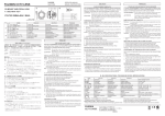
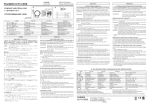
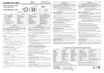
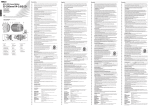
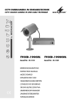
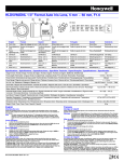
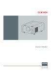
CCTV-FARBKAMERA
CCTV COLOUR CAMERA
TVCCD-400COL
Best.-Nr. 19.3560
BEDIENUNGSANLEITUNG
INSTRUCTION MANUAL
MODE D’EMPLOI
ISTRUZIONI PER L’USO
MANUAL DE INSTRUCCIONES
®
D
A
CH
F
B
CH
E
2
Bevor Sie einschalten ...
Wir wünschen Ihnen viel Spaß mit Ihrem
neuen MONACOR-Gerät. Bitte lesen Sie vor
dem Gebrauch diese Anleitung.
Der deutsche Text beginnt auf der Seite 4.
GB
Before you switch on
We wish you much pleasure with your new
MONACOR unit. Please read these instructions before use.
The English text starts on the page 9.
Avant toute utilisation
Nous vous remercionsd'avoir choisi un appareil MONACOR et vous prions de lire
cette notice.
La version française commence à la
page 14.
I
Prima di accendere
Vi auguriamo buon divertimento con il Vostro
nuovo apparecchio MONACOR. Vi preghiamo di leggere le presenti istruzioni prima dell'uso.
Il testo italiano inizia a pagina 19.
Antes de la conexión
Le agradecemos el haber adquirido un equipo
MONACOR. Por favor, lee atentamente las
instrucciones de uso.
La versión español comienza en la página 24.
BLC OFF
OFF
AGCMIN
GAMMA1
AUTO
IRIS
VIDEO
VIDEO OUT
FLICKERLESS
1/100S NTSC
1/120S PAL
DC
1 2 3 4 5
LEVEL
OFF
BLC ON
SHUTTER
AGCMAX
GAMMA2
➀
➁
1 2 3
4
5
6
3
4
➂
1
3
2
Schalter
AUTO IRIS (2)
Switch
VIDEO
DC
7
für AI-Objektiv
for AI lens
8
VIDEO
DC
9
für DC-Objektiv
for DC lens
Pin 1
Ausgang/output +12 V
Dämpfungsspule -/damp -
Pin 2
Ausgang Videosignal/output of video signal
Dämpfungsspule +/damp +
Pin 3
Masse/ground
Antriebsspule +/drive -
Pin 4
Masse/ground
Antriebsspule -/drive -
10
D
A
Bitte klappen Sie die Seite 3 heraus. Sie sehen
dann immer die beschriebenen Bedienelemente
und Anschlüsse.
CH
1 Übersicht der Bedienelemente und Anschlüsse
1 BNC-Buchse für den Videoausgang, 1 Vss an 75 Ω
2 Umschalter AUTO IRIS zur Einstellung der Kamera auf den verwendeten Objektivtyp,
siehe Tabelle auf der Seite 3
3 Regler LEVEL zum Einstellen des Arbeitspunktes
bei Verwendung eines DC-Objektives
4 Stromversorgungsanschluss für 12 V ,
Mittelkontakt = Pluspol
5 Buchse für den Anschluss eines Objektivs mit
automatischer Blendenregelung (Auto Iris),
Anschlussbelegung siehe Tabelle auf der Seite 3
6 DIP-Schalter zum Um- oder Ein- und Ausschalten
verschiedener Funktionen
1 GAMMA 1/2
Gammakorrektur 0,45 oder 1
2 AGC
autom. Verstärkungsregelung
3 SHUTTER
elektronischer Verschluss
4
4 BLC
Gegenlichtkompensation
5 FLICKERLESS Flimmerkompensation
7 Adapter mit 6,3-mm-Fotogewinde (1/4");
zur Deckenmontage den Adapter auf die Oberseite
der Kamera schrauben
8 Feststellschrauben zum Korrigieren des Auflagemaßes für das Objektiv
9 Adapterring zur Montage eines Objektivs mit
C-Mount-Gewinde
10 Schutzkappe
2 Hinweise für den sicheren Gebrauch
Die Kamera entspricht der EU-Richtlinie 89/336/
EWG für elektromagnetische Verträglichkeit.
● Die Kamera ist nur zur Verwendung im Innenbereich
geeignet. Bei einer Außenmontage muss sie in ein
wetterfestes Schutzgehäuse eingesetzt werden.
● Schützen Sie die Kamera vor Verschmutzung,
Feuchtigkeit und Hitze (zulässiger Einsatztemperaturbereich 0 – 40 °C).
● Verwenden Sie zum Reinigen nur ein trockenes, weiches Tuch, auf keinen Fall Chemikalien oder Wasser.
Wird die Kamera zweckentfremdet, falsch angeschlossen, nicht richtig bedient oder nicht fachgerecht repariert, kann für eventuelle Schäden keine
Haftung übernommen werden.
● Soll die Kamera endgültig aus dem Betrieb genommen werden, übergeben Sie sie zur umweltgerechten Entsorgung einem örtlichen Recyclingbetrieb.
●
3 Einsatzmöglichkeiten
Die PAL-Farbkamera TVCCD-400COL ist speziell für
den Einsatz in Videoüberwachungsanlagen konzipiert. Sie ist u. a. mit einer automatischen Verstärkungsregelung (AGC), einem automatischen elektronischen Verschluss (1/50 – 1/100 000 s), einem automatischem Weißabgleich (Bereich 2400 °K bis 11 000 °K)
und einer Gegenlichtkompensation ausgestattet.
4 Objektiv
Es kann sowohl ein Objektiv mit automatischer
Blendenregelung [AI-Objektiv oder DC-Objektiv (AISObjektiv)] als auch ein Objektiv mit manueller Blendeneinstellung verwendet werden.
1) Mit den Umschaltern AUTO IRIS (2) und SHUTTER (6) den verwendeten Objektivtyp einstellen:
Objektivtyp
videosignalgeregelt
gleichspannungsgesteuert (DC)
manuelle oder
feste Blende
Schalter
AUTO IRIS
Schalter
SHUTTER
VIDEO
OFF
DC
OFF
—
SHUTTER
(untere Position)
D
A
CH
2) Die Schutzkappe (10) abnehmen.
Achtung! Schützen Sie den CCD-BildwandlerChip und die Objektivlinsen vor Staub und Verschmutzung und berühren Sie sie auf keinen Fall
mit den Fingern.
3) Bei Verwendung eines C-Mount-Objektivs zuerst
den mitgelieferten C-Mount-Adapterring (9) auf die
Kamera schrauben und darauf das Objektiv. Bei
Verwendung eines CS-Mount-Objektivs den Adapterring (9) ggf. entfernen und das Objektiv direkt
auf die Kameravorderseite schrauben.
4) Bei einem Objektiv mit gesteuerter Blende dieses
an die Buchse AUTO IRIS (5) anschließen. Bei Be-
5
D
A
CH
darf den beiliegenden Stecker verwenden. Die
Buchse hat, abhängig von der Stellung des Schalters AUTO IRIS (2), folgende Pin-Belegung, siehe
auch Tabelle auf der Seite 3:
Pin
Position VIDEO
Position DC
1
Stromversorgung Pluspol
Dämpfungsspule -
2
Ausgang Videosignal
Dämpfungsspule +
3
Masse
Antriebsspule +
6 Kamera anschließen
4
Masse
Antriebsspule -
1) Die BNC-Ausgangsbuchse VIDEO OUT (1) über
ein 75-Ω-Kabel (z. B. VEC-62/10 von MONACOR)
mit einem Monitor verbinden. Dabei auf den korrekten 75-Ω-Abschluss am Monitor bzw. bei Serienschaltung am letzten Monitor achten. Bei einer
Kabellänge von mehr als 100 m sollte ein Videoverstärker zwischen die Kamera und das lange Kabel geschaltet werden, um die Kabelverluste auszugleichen.
Beim Einsatz von mehreren Kameras einen Video-Splitter (z. B. TVSP-46COL von MONACOR)
oder einen Kamera-Umschalter (z. B. TVS-40 oder
TVS-80 von MONACOR) zwischen die Kameras
und den Monitor schalten.
Achtung! Um Beschädigung von Kamera oder
Objektiv zu vermeiden, vor dem Anschluss des
Objektivs die Stellung des Schalters AUTO IRIS
und die Pin-Belegung des Steckers überprüfen.
5 Montage
Die Kamera kann mit einer Kamerahalterung (z. B.
TVH-Serie von MONACOR) an eine Wand oder Decke montiert werden. Dazu befindet sich auf der
Unterseite ein Adapter (7) mit einem 6,3-mm-Fotoge-
6
winde (1/4"). Für eine Deckenmontage den Adapter auf
die Oberseite der Kamera schrauben.
Bei einer Außenmontage muss die Kamera in ein
wetterfestes Schutzgehäuse (z. B. TVG-300 von
MONACOR) eingesetzt werden. Soll die Kamera ferngesteuert schwenkbar sein, ist ein Kamera-Rotor zu
verwenden (z. B. VPT-50 von MONACOR).
2) Die Betriebsspannung von 12 V
über einen
Kleinspannungsstecker 5,5/2,1 mm (Außen-/Innendurchmesser) an die Versorgungsbuchse (4)
[innerer Kontakt = Pluspol] anschließen. Es ist ein
elektronisch stabilisiertes Netzgerät mit einer Ausgangsspannung von 12 V erforderlich (z. B. PS12CCD oder PS-128A von MONACOR). Die
Stromaufnahme der Kamera beträgt 200 mA.
7 Inbetriebnahme
1) Nach dem Anlegen der Betriebsspannung ist die
Kamera betriebsbereit.
2) Nach dem Einschalten des Monitors die Kamera
auf den Überwachungsbereich ausrichten. Achten
Sie darauf, dass kein Sonnenlicht direkt auf die
Objektivlinsen trifft. Anderenfalls könnte der CCDBildwandler-Chip beschädigt werden!
3) Am Objektiv die Entfernung einstellen. Bei einem
Objektiv mit manuell einstellbarer Blende diese auf
optimale Bildwiedergabe (Schärfentiefe und Helligkeit) einstellen.
4) Ist bei korrekt eingestellter Entfernung das Bild unscharf, das Auflagemaß für das Objektiv korrigie-
ren. Dazu die Feststellschrauben (8) lösen. Durch
Verdrehen des Gewinderings (zusammen mit dem
Objektiv und eventuell dem Adapterring) ein scharfes Bild einstellen. Anschließend die Schrauben
wieder festziehen.
D
A
CH
5) Bei Verwendung eines Objektivs mit gleichspannungsgesteuerter Blende (DC-Objektiv) lässt sich
der Arbeitspunkt der Regelung korrigieren, falls
das Bild zu dunkel oder zu hell erscheint: Durch
Verdrehen des Reglers LEVEL (3) mit einem kleinen Schraubendreher die optimale Helligkeit einstellen. Bei Verwendung eines Objektivs mit videosignalgeregelter Blende befinden sich Regler am
Objektiv.
6) Einstellung der DIP-Schalter (6)
GAMMA 1/GAMMA 2 (Gammakorrektur)
Die Standardeinstellung ist GAMMA 1 für eine
Grauwertumsetzung von 0,45. Lässt sich der
Kontrast am Monitor nicht optimal einstellen,
den Schalter in die Position GAMMA 2 stellen.
AGC (automatische Verstärkungsreglung)
Die Standardeinstellung ist AGC MIN. Bei starken Lichtstärkeschwankungen kann ggf. in der
7
D
A
CH
Position AGC MAX ein besseres Ausregeln
durch die Kamera erreicht werden.
SHUTTER (elektronischer Verschluss)
Die Standardeinstellung für Objektive mit geregelter Blende ist OFF. Bei ausreichender Helligkeit und sich schnell bewegenden Objekten
kann in der unteren Position SHUTTER eine
größere Schärfe erreicht werden.
BLC (Gegenlichtkorrektur)
Stört kein Gegenlicht, den Schalter in die Position OFF stellen, sonst in die Position BLC ON.
FLICKERLESS (Flimmerkompensation)
Die Standardeinstellung ist OFF. Wenn das Bild
auf dem Monitor flimmert, den Schalter in die
obere Position FLICKERLESS stellen.
8 Technische Daten
Bildabtaster:. . . . . . . . . . . . . 8,5-mm-CCD-Chip (1/3")
Farbsystem:. . . . . . . . . . . . . PAL
Synchronisation: . . . . . . . . . horizontal 15 625 Hz,
vertikal 50 Hz (CCIR)
Anzahl der Bildpunkte:. . . . . hor. 500, vertikal 582
8
Auflösung: . . . . . . . . . . . . . . 420 Linien
Mindestbeleuchtung: . . . . . . 0,5 Lux bei Objektiv
1 : 0,75
autom. elektron. Verschluss: 1/50 – 1/100 000 s
Signal/Rauschabstand: . . . . > 50 dB
Ausgänge
Video: . . . . . . . . . . . . . . . 1 Vss/75 Ω (FBAS)
Blendenregelung: . . . . . . 1 Vss, 10 Ω
Gammakorrektur
Gamma 1: . . . . . . . . . . . . 0,45
Gamma 2: . . . . . . . . . . . . 1
autom. Verstärkungsreglung
AGC min.: . . . . . . . . . . . . normaler Modus
AGC max.: . . . . . . . . . . . +6 dB
zulässige Einsatztemperatur: 0–40 °C
Stromversorgung: . . . . . . . . 12 V , 200 mA
Abmessungen (B x H x T): . 48 x 43 x 143 mm
Gewicht, ohne Objektiv:. . . . 190 g
Laut Angaben des Herstellers.
Änderungen vorbehalten.
Please unfold page 3. Then you can always see the
operating elements and connections described.
1 Operating Elements and Connections
1 BNC jack for the video output, 1 Vpp at 75 Ω
2 Selector switch AUTO IRIS for adjusting the camera to the lens type used,
see table on page 3
3 Control LEVEL for adjusting the operating point
when using a DC lens
4 Power supply connection for 12 V ,
centre contact = positive pole
5 Jack for connecting a lens with automatic iris control (auto iris lens),
for pin configuration see table on page 3
6 DIP switches for selecting, activating and deactivating various functions
1 GAMMA 1/2
gamma correction 0.45 or 1
2 AGC
automatic gain control
3 SHUTTER
electronic shutter
4 BLC
backlight compensation
5 FLICKERLESS flicker compensation
7 Adapter with 6.3 mm (1/4") thread;
for ceiling suspension, screw the adapter onto the
upper side of the camera
8 Setscrews for adjusting the mechanical focus setting for the lens
9 Adapter ring for mounting a lens with C-mount
thread
10 Lens cover
GB
2 Safety Notes
The camera corresponds to the directive for electromagnetic compatibility 89/336/EEC.
● The camera is suitable for indoor use only. For outside installation, the camera must be mounted into a
weatherproof outdoor housing.
● Protect the camera against impurities, humidity, and
heat (admissible ambient temperature range
0 – 40 °C).
● For cleaning only use a dry, soft cloth; never use
chemicals or water.
● No liability for any damage will be accepted if the
camera is used for other purposes than originally in-
9
tended, if it is not correctly connected or operated or
not repaired in an expert way.
GB
●
If the camera is to be put out of operation definitively, take it to a local recycling plant for a disposal
which is not harmful to the environment.
Lens type
Switch
AUTO IRIS
Switch
SHUTTER
video signal
controlled
VIDEO
OFF
DC controlled
DC
OFF
—
SHUTTER
(lower position)
manual or fixed iris
3 Applications
The PAL colour camera TVCCD-400COL is specially
designed for applications in video surveillance systems. Among other features it is provided with an automatic gain control (AGC), an automatic electronic
shutter (1/50 – 1/100 000 s), an automatic white balance
(range 2400 °K to 11 000 °K), and a backlight compensation.
4 Lens
It is possible to use a lens with automatic iris control
[AI lens or DC lens (AIS lens)] or a lens with manual
iris control.
1) Adjust the lens type used with the selector
switches AUTO IRIS (2) and SHUTTER (6):
10
2) Remove the lens cover (10).
Attention! Protect the CCD image sensor chip
and the lenses of the lens assembly against dust
and other impurities; never touch them with your
fingers.
3) When using a C-mount lens, screw the supplied
C-mount adapter ring (9) onto the camera first,
then screw the lens onto the ring. When using a
CS-mount lens, remove the adapter ring (9), if required, then screw the lens directly onto the face of
the camera.
4) When using an auto iris lens, connect it to the jack
AUTO IRIS (5). If required, use the supplied plug.
Depending on the position of the switch AUTO IRIS
(2), the jack has the following pin configuration
(also see table on page 3):
Pin
Position VIDEO
Position DC
1
positive pole
of power supply
damp -
2
output of video signal
damp +
3
ground
drive +
4
ground
drive -
Attention! Prior to connecting the lens, check the
position of the switch AUTO IRIS and the pin configuration of the plug to prevent damage to the
camera or the lens.
5 Mounting
The camera can be mounted to a wall or ceiling by
means of a mounting bracket (e. g. MONACOR TVH
series). For this purpose, an adapter (7) with a 6.3 mm
(1/4") thread is provided on the lower side of the camera. For ceiling suspension, screw the adapter onto
the upper side of the camera.
For outside installation, the camera must be placed
in a weatherproof outdoor housing (e. g. MONACOR
TVG-300). For remote-controlled panning of the camera, use a pan/tilt head (e. g. MONACOR VPT-50).
GB
6 Connection
1) Connect the BNC output jack VIDEO OUT (1) to
a monitor via a 75 Ω cable (e. g. MONACOR
VEC-62/10). Observe the correct 75 Ω termination
on the monitor or, in case of series connection, on
the last monitor. With a cable length exceeding
100 m, a video amplifier should be inserted between the camera and the long cable to compensate cable losses.
When using several cameras, insert a video
splitter (e. g. MONACOR TVSP-46COL) or a camera switcher (e. g. MONACOR TVS-40 or TVS-80)
between the cameras and the monitor.
2) Connect the operating voltage of 12 V
to the
power supply jack (4) via a low-voltage plug 5.5/
2.1 mm (outside/inside diameter) [inner contact =
positive pole]. An electronically regulated power
supply unit with an output voltage of 12 V is re-
11
GB
quired (e. g. MONACOR PS-12CCD or PS-128A).
The current consumption of the camera is 200 mA.
7 Operation
1) After applying the operating voltage, the camera is
ready for operation.
2) After switching on the monitor, align the camera to
the surveillance zone in such a way that the lenses
of the lens assembly are not exposed to direct sunlight, otherwise the CCD image sensor chip might
be damaged!
3) Adjust the distance on the lens. In case of a lens
with manual iris control, adjust the iris to optimum
picture reproduction (depth of focus and brightness).
4) If the picture is not sharp despite a correctly adjusted distance, readjust the mechanical focus setting for the lens. For this purpose, release the setscrews (8). Bring the picture into focus by turning
the threaded ring (together with the lens and the
adapter ring, if required). Then retighten the
screws.
12
5) In case of a DC controlled lens, the operating point
of the control can be readjusted if the picture is too
dark or too bright: Adjust an optimum brightness by
turning the control LEVEL (3) with a small screwdriver. When using a lens with video signal controlled iris, the controls can be found on the lens.
6) Adjustment of the DIP switches (6)
GAMMA 1/GAMMA 2 (gamma correction)
The standard adjustment is GAMMA 1 for a grey
scale conversion of 0.45. If an optimum adjustment of the contrast on the monitor is impossible, set the switch to the position GAMMA 2.
AGC (automatic gain control)
The standard adjustment is AGC MIN. In case
of great variations in the luminous intensity, it
may be possible to obtain an optimum control
by the camera in the position AGC MAX.
SHUTTER (electronic shutter)
The standard adjustment for lenses with iris control is OFF. In case of sufficient brightness and
fast-moving objects, enhanced focussing can be
obtained in the lower position SHUTTER.
BLC (backlight compensation)
Without any disturbing backlight, set the switch
to position OFF, otherwise to position BLC ON.
FLICKERLESS (flicker compensation)
The standard adjustment is OFF. In case of flickering of the picture on the monitor, set the
switch to the upper position FLICKERLESS.
8
Specifications
Image sensor: . . . . . . . . . . . 8.5 mm (1/3") CCD chip
Colour system:. . . . . . . . . . . PAL
Synchronization: . . . . . . . . . horizontal 15 625 Hz,
vertical 50 Hz (CCIR)
Number of pixels:. . . . . . . . . hor. 500, vertical 582
Resolution:. . . . . . . . . . . . . . 420 lines
Minimum illumination: . . . . . 0.5 lux for lens 1 : 0.75
Automatic electronic shutter: 1/50 – 1/100 000 s
S/N ratio: . . . . . . . . . . . . . . . > 50 dB
Outputs
video: . . . . . . . . . . . . . . . 1 Vpp/75 Ω (FBAS)
iris control:. . . . . . . . . . . . 1 Vpp, 10 Ω
Gamma correction
Gamma 1: . . . . . . . . . . . .
Gamma 2: . . . . . . . . . . . .
Automatic gain control
AGC min.: . . . . . . . . . . . .
AGC max.: . . . . . . . . . . .
Admissible ambient
temperature: . . . . . . . . . . . .
Power supply: . . . . . . . . . . .
Dimensions (W x H x D): . . .
Weight without lens: . . . . . .
GB
0.45
1
normal mode
+6 dB
0 – 40 °C
12 V , 200 mA
48 x 43 x 143 mm
190 g
According to the manufacturer.
Subject to technical change.
13
F
Ouvrez le présent livret page 3 de manière à visualiser les éléments et branchements.
B
CH
14
1 Eléments et branchements
1 Prise BNC pour la sortie vidéo, 1 Vcc/75 Ω
2 Commutateur AUTO IRIS pour régler la caméra
sur le type d’objectif utilisé, voir tableau page 3
3 Potentiomètre de réglage LEVEL pour régler le
point de travail si on utilise un objectif à commande
par tension DC
4 Borne de connexion alimentation pour une tension
12 V , contact médian = pôle plus
5 Prise pour brancher un objectif à commande automatique de réglage (auto iris) ;
voir tableau page 3 pour la configuration
6 Interrupteurs DIP pour activer/désactiver/commuter diverses fonctions :
1 GAMMA 1/2
correction gamma 0,45 ou 1
2 AGC
adaptation automatique d’un niveau de sortie constant selon les
variations de lumière
3 SHUTTER
obturation électronique
4 BLC
compensation du contre-jour
5 FLICKERNESS compensation scintillement
7 Adaptateur avec filetage 6,3 mm (1/4") ;
pour un montage au plafond, vissez l’adaptateur
sur la face supérieure de la caméra
8 Vis de réglage pour corriger les réglages de l’objectif
9 Anneau adaptateur pour monter un objectif à filetage C-Mount
10 Cache de protection
2 Conseils d’utilisation et de sécurité
La caméra répond à la norme européenne 89/336/
CEE relative à la compatibilité électromagnétique.
● La caméra n’est conçue que pour une utilisation en
intérieur. Pour un montage en extérieur, elle doit
être placée dans un boîtier de protection étanche.
● Protégez la caméra de la poussière, de l’humidité et
de la chaleur (plage de température de fonctionnement autorisée : 0 – 40 °C).
● Pour la nettoyer, utilisez un chiffon sec et doux, en
aucun cas de produits chimiques ou d’eau.
● Nous déclinons toute responsabilité en cas de dommage si la caméra est utilisée dans un but autre que
celui pour lequel elle a été conçue, si elle n’est pas
correctement branchée, utilisée ou réparée par une
personne habilitée.
● Lorsque la caméra est définitivement retirée du
marché, vous devez la déposer dans une usine de
recyclage de proximité pour contribuer à son élimination non polluante.
3 Possibilités de fonctionnement
La caméra PAL couleur TVCCD-400COL est spécialement conçue pour une utilisation dans des installations de surveillance vidéo. Elle est dotée d’une adaptation automatique d’un niveau de sortie constant selon les variations de lumière (AGC), d’une obturation
électronique automatique (1/50 – 1/100 000 s), d’une
compensation automatique du blanc (plage 2400 °K à
11 000 °K) et d’une compensation du contre-jour.
4 Objectif
Il est possible d’utiliser un objectif à commande automatique de diaphragme [objectif Al ou objectif DC
(AIS)] tout comme un objectif à réglage manuel de
diaphragme.
1) Avec le commutateur AUTO IRIS (2), et le interrupteur SHUTTER (6), réglez le type d’objectif utilisé :
interrupteur
interrupteur
Type objectif
AUTO IRIS
SHUTTER
A commande par
VIDEO
OFF
signal vidéo
A commande par
DC
OFF
tension DC
Diaphragme à réSHUTTER
—
glage manuel ou fixe
(position inférieure)
F
B
CH
2) Retirez le cache de protection (10).
Attention ! Protégez la puce CCD et les lentilles
de l’objectif de la poussière et de toute salissure,
ne les touchez jamais avec les doigts.
3) Si vous utilisez un objectif C-Mount, vissez tout d’
abord l’anneau adaptateur C-Mount livré (9) sur la
caméra et vissez l’objectif dessus. Si vous utilisez
un objectif CS-Mount, retirez l’anneau (9) si besoin
et vissez directement l’objectif sur la face avant de
la caméra.
4) Dans le cas d’un objectif à commande de diaphragme par tension, connectez-le à la prise
AUTO IRIS (5). Si besoin, utilisez la fiche livrée. La
15
F
B
CH
prise a, en fonction de la position du commutateur
AUTO IRIS (2) la configuration suivante, voir tableau sur la page 3 :
position DC
Pin
position VIDEO
1
alimentation pôle plus
bobine atténuation -
2
sortie signal vidéo
bobine atténuation +
6 Branchements de la caméra
3
masse
bobine moteur +
4
masse
bobine moteur -
1) Reliez la prise de sortie BNC VIDEO OUT (1) via
un câble 75 Ω (VEC-62/10 de MONACOR p. ex.) à
un moniteur. Veillez à ce que le branchement 75 Ω
sur le moniteur ou, pour un branchement en série,
sur le dernier moniteur, soit correctement effectué.
Pour une longueur de câble supérieure à 100 m, il
est conseillé d’installer un amplificateur vidéo entre
la caméra et le long câble de manière à compenser
les pertes en ligne.
Si vous utilisez plusieurs caméras, un répartiteur vidéo (TVSP-46COL de MONACOR p. ex.) ou
un sélecteur de caméra (TVS-40 ou TVS-80 de
MONACOR p. ex.) doit être branché entre les caméras et le moniteur.
2) Connectez la tension de fonctionnement 12 V
via un adaptateur 5,5/2,1 mm (diamètre extérieur/
diamètre intérieur) à la prise d’alimentation (4)
Attention : Pour éviter tout dommage sur la caméra ou l’objectif, vérifier la position du commutateur AUTO IRIS et la configuration de la fiche
avant de brancher l’objectif.
5 Montage
La caméra peut être montée avec un support de caméra (p. ex. série TVH- de MONACOR) à un mur ou
un plafond. Pour ce faire, un adaptateur (7) avec un filetage 6,3 mm (1/4") se trouve sur la face inférieure.
Pour un montage au plafond, vissez l’adaptateur sur
la face supérieure de la caméra.
16
Pour un montage en extérieur, la caméra doit être
placée dans un boîtier de protection étanche (TVG300 de MONACOR par exemple). Si la caméra doit
être orientée à distance, un rotor de caméra doit être
utilisé (VPT-50 de MONACOR p. ex.).
[contact intérieur : pôle plus]. Une alimentation stabilisée électroniquement avec une tension de sortie de 12 V est nécessaire (PS-12CCD ou PS-128A
de MONACOR p. ex.). La consommation est de
200 mA.
7 Fonctionnement
1) Une fois la tension de fonctionnement appliquée,
la caméra est prête à fonctionner.
2) Une fois le moniteur allumé, dirigez la caméra sur
la zone à surveiller. Veillez à ce qu’aucun rayon du
soleil n’éclaire directement les lentilles de l’objectif,
la puce CCD pourrait être endommagée.
3) Sur l’objectif, réglez la distance : pour un objectif à
réglage manuel de diaphragme, réglez-la pour une
restitution optimale de l’image (profondeur de
champ et luminosité).
4) Si l’image manque de netteté malgré un réglage
correct de la distance, il convient d’effectuer certains réglage sur l’objectif : desserrez les vis de
réglages (8). En tournant l’anneau fileté (avec l’objectif et le cas échéant l’anneau adaptateur), réglez
une image nette. Revissez ensuite les vis.
5) Si vous utilisez un objectif à commande par tension DC (objectif DC), le point de travail du réglage
peut être corrigé dans le cas où l’image est trop
sombre ou trop claire. En tournant le potentiomètre
de réglage LEVEL (3) avec un petit tournevis, réglez la luminosité optimale. Si vous utilisez un objectif à commande de diaphragme par signal vidéo,
les réglages se trouvent sur l’objectif.
6) Réglage des interrupteurs DIP (6)
GAMMA 1/GAMMA 2 (correction gamma)
Le réglage standard est GAMMA 1 pour une
conversion des niveaux de gris de 0,45. Si le
contraste sur le moniteur ne peut être réglé de
manière optimale, mettez le sélecteur sur la position GAMMA 2.
AGC (adaptation automatique d’un niveau de sortie constant selon les variations de lumière)
Le réglage standard est AGC MIN. En cas de
fluctuations importantes de la luminosité, il est
possible d’atteindre un meilleur réglage dans la
position AGC MAX.
SHUTTER (obturation électronique)
Le réglage standard pour des objectifs à commande de diaphragme est sur OFF. Si la lumi-
F
B
CH
17
F
B
CH
nosité est suffisante, et pour des objets se déplaçant rapidement, il est possible d’obtenir
plus grande précision en mettant le réglage sur
la position inférieure SHUTTER.
BLC (correction contre-jour)
S’il n’y a pas de contre-jour, mettez le commutateur sur la position OFF, sinon sur la position
BLC ON.
FLICKERNESS (compensation scintillement)
Le réglage standard est sur OFF ; si sur le moniteur, l’image scintille, mettez le réglage sur la
position supérieure FLICKERNESS.
8 Caractéristiques techniques
Système :. . . . . . . . . . . . . . . puce CCD, 8,5 mm (1/3")
Système couleur : . . . . . . . . PAL
Synchronisation : . . . . . . . . . horizontal 15 625 Hz,
vertical 50 Hz (CCIR)
Nombre de points : . . . . . . . horizontal 500,
vertical 582
Résolution : . . . . . . . . . . . . . 420 lignes
18
Luminosité minimale : . . . . . 0,5 lux pour objectif
1 : 0,75
Obturation électr. autom. :. . 1/50 – 1/100 000 s
Rapport signal/bruit :. . . . . . > 50 dB
Sorties
Vidéo : . . . . . . . . . . . . . . . 1 Vcc/75 Ω (FBAS)
Réglage diaphragme :. . . 1 Vcc, 10 Ω
Correction gamma
Gamma 1 : . . . . . . . . . . . 0,45
Gamma 2 : . . . . . . . . . . . 1
Réglage AGC
AGC min. : . . . . . . . . . . . mode normal
AGC max. : . . . . . . . . . . . +6 dB
Temp. fonction. autorisée : . 0 – 40 °C
Alimentation :. . . . . . . . . . . . 12 V , 200 mA
Dimensions (L x H x P) : . . . 48 x 43 x 143 mm
Poids sans objectif :. . . . . . . 190 g
D’après les données du constructeur.
Tout droit de modification réservé.
Vi preghiamo di aprire completamente la pagina 3.
Così vedrete sempre gli elementi di comando e i
collegamenti descritti.
1 Comandi e collegamenti
1 Presa BNC per l’uscita video, 1 Vpp su 75 Ω
2 Commutatore AUTO IRIS per impostare la telecamera secondo il tipo di obiettivo,
vedi tabella a pag. 3
3 Regolatore LEVEL per impostare il punto di lavoro
usando un obiettivo DC
4 Presa di alimentazione per 12 V ;
contatto centrale = positivo
5 Presa per il collegamento di un obiettivo con regolazione automatica del diaframma (auto iris);
per i contatti vedi tabella a pag. 3
6 Dip-switch per selezionare o dis/attivare diverse
funzioni
1 GAMMA 1/2
correzione del gamma 0,45 o 1
2 AGC
regolazione automatica del guadagno
3 SHUTTER
otturatore elettronico
4 BLC
compensazione della controluce
5 FLICKERLESS compensazione dello sfarfallio
7 Adattatore con filettatura 6,3 mm (1/4") [tipo fotografico];
per il montaggio al soffitto avvitare l’adattatore sul
lato superiore della telecamera
8 Viti di fissaggio per correggere la posizione dell’
obiettivo
9 Anello adattatore per avvitare un obiettivo C-mount
10 Cappuccio di protezione
I
2 Avvertenze di sicurezza
La telecamera è conforme alla direttiva UE 89/366/
CEE sulla compatibilità elettromagnetica.
● La telecamera è prevista solo per l’uso in locali. Nel
caso di montaggio all’esterno occorre sistemarla in un
contenitore di protezione resistente alle intemperie.
● Proteggere la telecamera dallo sporco, dall’umidità
e dal calore (temperatura d’impiego ammessa
0 – 40 °C).
● Per la pulizia usare solo un panno morbido, asciutto; non impiegare in nessun caso prodotti chimici
o acqua.
19
I
Nel caso di uso improprio della telecamera, di collegamenti sbagliati, di impiego scorretto o di riparazione non a regola d’arte non si assume nessuna
responsabilità per eventuali danni.
● Se si desidera eliminare la telecamera definitivamente, consegnarla per lo smaltimento ad un’istituzione locale per il riciclaggio.
●
3 Possibilità d’impiego
La telecamera PAL a colore TVCCD-400 COL è realizzata in particolar modo per l’impiego in impianti di
sorveglianza video. La telecamera è equipaggiata fra
l’altro con regolazione automatica del guadagno
(AGC), con un otturatore elettronico automatico
(1/50 – 1/100 000 sec.), con compensazione automatica
del bianco (da 2400 °K fino a 11000 °K) e con compensazione della controluce.
4 Obiettivo
20
Si possono utilizzare sia obiettivi con regolazione
automatica del diaframma [obiettivi AI o DC (AIS)] che
obiettivi con regolazione manuale del diaframma.
1) Con i commutatori AUTO IRIS (2) e SHUTTER (6)
impostare il tipo di obiettivo impiegato:
Tipo di obiettivo
regolazione dal
segnale video
comandato dalla
tensione continua
(DC)
diaframma
manuale o fisso
Commutatore
AUTO IRIS
Commutatore
SHUTTER
VIDEO
OFF
DC
OFF
—
SHUTTER
(posizione inferiore)
2) Staccare il cappuccio di protezione (10).
Attenzione! Proteggere il chip del sensore CCD
assolutamente dalla polvere o da ogni altro tipo di
sporco. Non toccarlo in nessun caso con le dita.
3) Nel caso di utilizzo di un obiettivo con filettatura
C-mount avvitare dapprima l’anello adattatore (9)
in dotazione sulla telecamera e su di esso l’obiettivo. Nel caso di utilizzo di un obiettivo con filettatura CS-mount svitare eventualmente l’anello adattatore (9) ed avvitare l’obiettivo direttamente sul
lato anteriore della telecamera.
4) Nel caso di utilizzo di un obiettivo con diaframma
comandato, collegare l’obiettivo con la presa
AUTO IRIS (5). Se necessario, utilizzare la spina in
dotazione. La presa presenta, a seconda della posizione del commutatore AUTO IRIS (2), i seguenti
contatti; vedi anche la tabella a pag. 3:
Per il montaggio all’esterno, la telecamera deve
essere protetta da una custodia (p. es. TVG-300 della
MONACOR). Se la telecamera deve essere orientabile mediante telecomando, occorre impiegare un apposito rotore (p. es. VPT-50 della MONACOR).
Pin
Posizione VIDEO
Posizione DC
1
Alimentazione positivo
Bobina di smorzamento -
2
Uscita segnale video
Bobina di smorzamento +
3
Massa
Bobina di azionamento +
6 Collegamento della telecamera
4
Massa
Bobina di azionamento -
1) Collegare la presa d’uscita VIDEO OUT (1) con un
monitor, utilizzando un cavo 75 Ω (p. es. VEC-62/10
della MONACOR). Controllare bene la corretta terminazione 75 Ω sul monitor o sull’ultimo monitor nel
caso di un collegamento in serie. Se il cavo supera i
100 metri si dovrebbe inserire un amplificatore del
segnale video fra telecamera e cavo per compensare le perdite dovute al cavo.
Se si usano diverse telecamere occorre inserire un videosplitter (p. es. TVSP-46COL della
MONACOR) oppure un selettore (p. es. TVS-40 o
TVS-80 della MONACOR) fra le telecamere ed il
monitor.
Attenzione! Per non danneggiare la telecamera
o l’obiettivo, verificare la posizione del commutatore AUTO IRIS e i contatti della spina prima di
collegare l’obiettivo.
5 Montaggio
La telecamera può essere montata alla parete o al
soffitto mediante l’impiego di un supporto (p. es. serie
TVH-... della MONACOR). A tale scopo, sul lato inferiore si trova un adattatore (7) con una filettatura tipo
apparecchio fotografico 6,3 mm (1/4"). Per il montaggio
al soffitto avvitare l’adattatore sul lato superiore della
telecamera.
2) Applicare la tensione d’esercizio di 12 V
alla
presa d’alimentazione (4) [contatto interno = positivo] per mezzo di un connettore per piccole ten-
I
21
I
sioni 5,5/2,1 mm (diametro esterno/interno). È
richiesto un alimentatore stabilizzato elettronicamente con tensione d’uscita di 12 V (p. es. PS12CCD o PS-128A della MONACOR). L’assorbimento della telecamera è 200 mA.
7 Messa in funzione
1) Dopo aver applicata la tensione di alimentazione,
la telecamera è pronta per l’uso.
2) Dopo aver acceso il monitor, orientare la telecamera sulla zona da sorvegliare. Fare attenzione
che la luce del sole non colpisca direttamente le
lenti dell’obiettivo, altrimenti il sensore ottico potrebbe essere danneggiato.
3) Regolare la distanza sull’obiettivo. Per gli obiettivi
con regolazione manuale del diaframma portare il
diaframma al massimo rendimento (profondità di
campo e luminosità).
4) Se con una distanza corretta, l’immagine non è a
fuoco, occorre correggere la posizione dell’obiettivo. A tale scopo allentare le viti di fissaggio (8).
Mettere a fuoco l’immagine, girando l’anello filet-
22
tato (con l’obiettivo e eventualmente anche con l’anello adattatore). Quindi stringere di nuovo le viti.
5) Se si utilizza un obiettivo con diaframma comandato dalla tensione continua (obiettivo DC), è possibile correggere il punto di lavoro della regolazione quando l’immagine pare troppo scura o
troppo chiara. Girando il regolatore LEVEL (3) per
mezzo di un piccolo cacciavite, si può impostare la
luminosità ottimale. Se si utilizza un obiettivo con
diaframma regolato dal segnale video, i regolatori
si trovano sull’obiettivo stesso.
6) Impostazione dei dip-switch (6)
GAMMA 1/GAMMA 2 (correzione del gamma)
L’impostazione standard è GAMMA 1 con un
valore dei grigi di 0,45. Se il contrasto sul monitor non può essere regolato in maniera ottimale, portare il selettore su GAMMA 2.
AGC (regolazione automatica del guadagno)
L’impostazione standard è AGC MIN. Di fronte
a forti oscillazioni della luminosità, la posizione
AGC MAX può permettere eventualmente una
regolazione migliore della telecamera.
SHUTTER (otturatore elettronico)
L’impostazione standard per obiettivi con dia-
framma regolato è OFF. Se la luminosità è sufficiente e se gli oggetti si muovono velocemente, la posizione inferiore SHUTTER può migliorare la messa a fuoco.
BLC (compensazione della controluce)
Se non è presente una controluce che disturba,
portare il commutatore in posizione OFF, altrimenti su BLC ON.
FLICKERLESS (compensazione dello sfarfallio)
L’impostazione standard è OFF. Nel caso di sfarfallio dell’immagine sul monitor, portare il commutatore nella posizione superiore FLICKERLESS.
8 Dati tecnici
Sensore ottico:. . . . . . . . . . . chip CCD 8,5 mm (1/3")
Sistema colore: . . . . . . . . . . PAL
Luminosità minima: . . . . . . . 0,5 lux con obiettivo
1 : 0,75
Otturatore elet. autom.: . . . . 1/50 – 1/100 000 s
Rapporto S/R: . . . . . . . . . . . > 50 dB
Uscite
video: . . . . . . . . . . . . . . . 1 Vpp/75 Ω (FBAS)
regolazione diaframma: . 1 Vpp/10 Ω
Correzione del gamma
Gamma 1: . . . . . . . . . . . . 0,45
Gamma 2: . . . . . . . . . . . . 1
Regolazione autom. del guadagno
AGC min.: . . . . . . . . . . . . modalità normale
AGC max.: . . . . . . . . . . . +6 dB
Temp. d’esercizio ammessa: 0–40 °C
Alimentazione: . . . . . . . . . . . 12 V , 200 mA
Dimensioni (l x h x p): . . . . . 48 x 43 x 143 mm
Peso (senza obiettivo): . . . . 190 g
I
Sincronizzazione: . . . . . . . . 15 625 Hz orizz.,
50 Hz vert. (CCIR)
Numero pixel: . . . . . . . . . . . 500 orizz. x 582 vert.
Risoluzione: . . . . . . . . . . . . . 420 righe
Dati forniti dal costruttore.
Con riserva di modifiche tecniche.
23
E
Abrir el libro página 3 de manera a visualizar los
elementos y las conexiones.
1 Elementos y conexiones
24
1 Toma BNC para la salida vídeo, 1 Vcc/75 Ω
2 Conmutador AUTO IRIS para regular la cámara en
el tipo de objetivo utilizado, vea tabela página 3
3 Potenciómetro de reglaje LEVEL para regular el
punto de trabajo si se utiliza un objetivo con mando
por tensión DC
4 Borne de conexión de alimentación para una tensión 12 V ,
contacto mediano = polo positivo
5 Toma para conectar un objetivo con mando automático de reglaje (auto iris);
vea tabela página 3 para la configuración
6 Interruptores DIP para activar/desactivar/conmutar diversas funciones:
1 GAMMA 1/2
corrección gamma 0,45 o 1
2 AGC
reglaje automático de la amplificación
3 SHUTTER
obturación electrónica
4 BLC
compensación de la contraluz
5 FLICKERNESS compensación centelleo
7 Adaptador con fileteado 6,3 mm (1/4");
para un montaje en techo, atornille el adaptador en
la parte superior de la cámara
8 Tuercas de reglaje para corregir el reglaje del objetivo
9 Anilla adaptadora para montar un objetivo con fileteado C-Mount
10 Tapa de protección
2 Consejos de utilización y seguridad
La cámara responde a la normativa europea 89/336/
CEE relacionada con la compatibilidad electromagnética.
● La cámara está fabricada solo para una utilización
en interior. Para un montaje exterior, debe instalarse en un caja de protección estanca.
● Protégela de la suciedad, de la humedad y del calor
(temperatura de funcionamiento autorizado:
0 – 40 °C).
● Para limpiarla, utilice un trapo seco y blando, en
ningún caso productos químicos o agua.
Rechazamos toda responsabilidad en caso de daños si la cámara se utiliza en otro fin para el cual ha
sido fabricada, si no se conecta o utiliza correctamente o repara por una persona habilitada.
● Cuando la cámara está definitivamente sacada del
servicio, debe depositarla en una fábrica de reciclaje a proximidad para contribuir a una eliminación
no contaminante.
●
3 Posibilidades de funcionamiento
La cámara PAL color TVCCD-400COL está especialmente fabricada para una utilización en instalaciones
de vigilancia vídeo. Dispone de un reglaje automático
de amplificación (AGC), de una obturación electrónica
automática (1/50 – 1/100 000 s), de una compensación
automática del blanco (2400 °K a 11 000 °K) y de una
compensación de la contraluz.
4 Objetivo
Es posible de utilizar un objetivo con mando automático de diafragma [objetivo Al o objetivo DC (objetivo
AIS)] tanto como un objetivo con reglaje manual de
diafragma.
1) Con los interruptores AUTO IRIS (2) y SHUTTER
(6), regule el tipo de objetivo utilizado:
Tipo de objetivo
Con mando por
señal vídeo
Con mando por
tensión (DC)
Diafragma con
reglaje
Interruptor
AUTO IRIS
Interruptor
SHUTTER
VIDEO
OFF
DC
OFF
—
SHUTTER
(posición inferior)
E
2) Saque la tapa de protección (10).
¡Atención! Proteja la lente CCD y las lentes del
objetivo del polvo y de toda suciedad, no las manipule nunca con los dedos.
3) Si se utiliza un objetivo C-Mount, atornille antes de
todo la anilla adaptadora C-Mount entregada (9)
con la cámara y atornille el objetivo encima. Si se
utiliza un objetivo CS-Mount, saque la anilla (9), si
es necesario, y atornille directamente el objetivo
en la parte delantera de la cámara.
4) En el caso de un objetivo con mando de diafragma, conéctelo con la toma AUTO IRIS (5). Si
es necesario, utilice la toma entregada. La toma,
25
E
en funcion de la posición del conmutador AUTO
IRIS (2), tiene la configuración siguiente, vea tabela en la página 3:
Pin
Posición VIDEO
1
alimentación polo positivo bobina atenuación -
Posición DC
2
salida señal vídeo
bobina atenuación +
3
masa
bobina motor +
4
masa
bobina motor -
¡Atención! Para evitar todo daño en la cámara o
el objetivo, verifique la posición del conmutador
AUTO IRIS y la configuración de la toma antes de
conectar el objetivo.
5 Montaje
La cámara puede montarse con un soporte de cámara
(la serie TVH- de MONACOR p. ej.) en pared o en techo. Para efectuar el montaje, hay un adaptador (7)
con un fileteado de 6,3 mm (1/4") en la parte inferior.
Para un montaje en techo, atornille el adaptador en la
parte superior de la cámara.
26
Para un montaje en exterior, la cámara debe estar
colocada en una caja de protección estanca (TVG-300
de MONACOR p. ej.). Si la cámara debe estar orientada a distancia, debe utilizar un rotor de cámara
(VPT-50 de MONACOR p. ej.).
6 Conexiones de la cámara
1) Conecte la toma de salida BNC VIDEO OUT (1)
con un cable 75 Ω (VEC-62/10 de MONACOR
p. ej.) con un monitor. Verifique que la conexión
75 Ω en el monitor o, para una conexión en serie,
en él último monitor, sea correctamente efectuada.
Para una longitud de cable superior a 100 m, le
aconsejamos instalar un amplificador vídeo entre
la cámara y el cable de manera a compensar las
perdidas en línea.
Si se utiliza varias cámaras, conecte un repartidor vídeo (TVSP-46COL de MONACOR p. ej.) o
un selector de cámara (TVS-40 o TVS-80 de
MONACOR p. ej.) entre las cámaras y el monitor.
2) Conecte la tensión de funcionamiento 12 V a través un adaptador de baja tensión 5,5/2,1 mm (diámetro exterior/diámetro interior) con la toma de ali-
mentación (4) [contacto interior: polo positivo]. Una
alimentación estabilizada electrónicamente con
una tensión de salida de 12 V es necesaria
(PS-12CCD o PS-128A de MONACOR p. ej.). El
consumo es de 200 mA.
7 Funcionamiento
1) Una vez la tensión de funcionamiento aplicada, la
cámara está lista para funcionar.
2) Una vez el monitor conectado, dirige la cámara en
la zona de vigilancia. Verifique que ningún rayo de
sol ilumine directamente las lentes del objetivo, la
lente CCD podría sufrir daños.
3) En el objetivo, regule la distancia. Para un objetivo
con reglaje manual de diafragma, regúlela para
una restitución óptima de la imagen (nitidez y luminosidad).
4) Si la imagen no es nítida a pesar de un reglaje correcto de la distancia, le aconsejamos de efectuar
algunos reglajes en el objetivo: destornille las tuercas de reglajes (8). Girando la anilla fileteada (con
el objetivo y, si es necesario, la anilla adaptadora),
regule una imagen nítida. Atornille después las
tuercas.
5) Si se utiliza un objetivo con mando por tensión DC
(objetivo DC), el punto de trabajo del reglaje puede
corrigirse en el caso la imagen está demasiada oscura o demasiada clara: Girando el potenciómetro
del reglaje LEVEL (3) con un pequeño destornillador, regule la luminosidad óptima. Sí se utiliza un
objetivo con mando de diafragma por señal vídeo,
los reglajes se hacen en el objetivo.
6) Reglaje de los interruptores DIP (6)
GAMMA 1/GAMMA 2 (corrección gamma)
El reglaje estándar es GAMMA 1, la conversión
de los niveles de gris es de 0,45. Si el contraste
en el monitor no puede estar regulado de manera óptima, ponga el selector en la posición
GAMMA 2.
AGC (reglaje automático de amplificación)
El reglaje estándar es AGC MIN. En caso de
fluctuaciones importantes de la luminosidad, es
posible alcanzar un mejor reglaje en la posición
AGC MAX, si es necesario.
SHUTTER (obturación electrónica)
El reglaje estándar para objetivos con mando
E
27
E
de diafragma está en OFF. Si la luminosidad es
suficiente, y para un reglaje de los objetivos
que se desplazan rápidamente, es posible obtener una precisión más grande poniendo el reglaje en la posición inferior SHUTTER.
BLC (corrección contraluz)
Si no hay contraluz, ponga el conmutador en la
posición OFF, sino en la posición BLC ON.
FLICKERNESS (compensación centelleo)
el reglaje estándar está en OFF; si en el monitor,
la imagen en el monitor tiene un centelleo, ponga
el reglaje en la posición superior FLICKERNESS.
8 Características técnicas
Sistema:. . . . . . . . . . . . . . . . lente CCD, 8,5 mm (1/3")
Sistema color: . . . . . . . . . . . PAL
Sincronización: . . . . . . . . . . horizontal 15 625 Hz,
vertical 50 Hz (CCIR)
Cantidad de puntos: . . . . . . horizontal 500,
vertical 582
Resolución: . . . . . . . . . . . . . 420 líneas
28
Luminosidad mínima: . . . . . 0,5 lux para objetivo
1 : 0,75
Obturación elec. auto.: . . . . 1/50 – 1/100 000 s
Relación señal ruido:. . . . . . > 50 dB
Salidas
Vídeo: . . . . . . . . . . . . . . . 1 Vcc/75 Ω (FBAS)
Reglaje diafragma: . . . . . 1 Vcc, 10 Ω
Corrección gamma
Gamma 1: . . . . . . . . . . . . 0,45
Gamma 2: . . . . . . . . . . . . 1
Reglaje amplificación automática
AGC min.: . . . . . . . . . . . . modo normal
AGC max.: . . . . . . . . . . . +6 dB
Temperatura funcionamiento
autorizado . . . . . . . . . . . . . . 0 – 40 °C
Alimentación: . . . . . . . . . . . . 12 V , 200 mA
Dimensiones (L x A x P): . . . 48 x 43 x 143 mm
peso sin objetivo:. . . . . . . . . . . 190 g
Según datos del fabricante.
Todo derecho de modificacion reservado.
®
Copyright © by MONACOR ® INTERNATIONAL GmbH & Co. KG, Bremen, Germany
All rights reserved. www.monacor.com
A-0005.99.02.07.2002