1
POWERLOGIC® Input/Output Option Card IOC44
Setting Up the IOC44 Card in SMS
SETTING UP THE IOC44 CARD
63230-303-200R/A2
7/2000
After you have installed the IOC44 card and restored power to the circuit
monitor and equipment, the circuit monitor automatically recognizes that the
IOC44 card is installed. Then, you need to set up the IOC44 from the display
or from SMS as described in the sections that follow.
When setting up inputs and outputs of the IOC44 card, you can give them a
new name (label) and change the operating mode. See the Input/Output
Capabilities and Operation chapters in the Circuit Monitor Series 4000
instruction bulletin (no. 63230-300-203) for more about operating inputs and
outputs. For relays that are set to circuit monitor alarm control, you can
associate one or more alarms with the relay.
About I/O Point Numbers
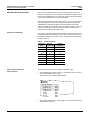
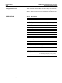
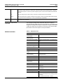
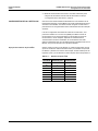
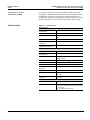
Each input or output is assigned a unique I/O point number, which the circuit
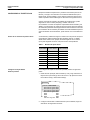
monitor uses internally to identify each I/O. Table 1 lists these numbers. For
example, the digital input S1 in slot A (A-S1) is assigned the corresponding
I/O point number 3.
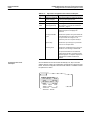
Table 1:
Setting Up the IOC44 Card
from the Display
I/O Point Numbers
IOC44 Card
Label
Slot A I/O
Point Number
Slot B I/O
Point Number
S1
3
19
S2
4
20
S3
5
21
S4
6
22
R1
7
23
R2
8
24
R3
9
25
R0
10
26
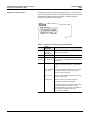
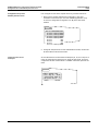
To set up the IOC44 card from the display, follow these steps:
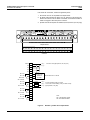
1. From the Main Menu, select Setup > I/O, and select the IOC44 card that
you installed (either slot A or slot B).
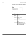
The IOC44 Slot A (or B) Setup menu displays.
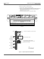
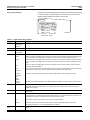
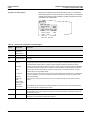
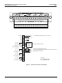
IOC-44 SETUP
Digital In
Digital In
Digital In
Digital In
Relay
Relay
Relay
Dig Out
BS1
BS2
BS3
BS4
BR1
BR2
BR3
BR0
2. Set up each individual input or output that you have wired, as described
in the following sections.
8
© 2000 Schneider Electric All Rights Reserved