1
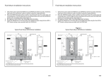
63249-402-200/A2
1/2002
Instruction Bulletin
Power Supply
for use with POWERLINK™ G3 systems
para utilizarse en los sistemas POWERLINK™ G3 (instructionnes en español: page 9)
CONTENTS
CONTENTS . . . . . . . . . . . . . . . . . . . . . . . . . . . . . . . . . . . . . . . . . . . . . . .1
INTRODUCTION . . . . . . . . . . . . . . . . . . . . . . . . . . . . . . . . . . . . . . . . . . .2
INSTALLING THE POWER SUPPLY . . . . . . . . . . . . . . . . . . . . . . . . . . . .3
CONNECTING TO A CONTROLLER . . . . . . . . . . . . . . . . . . . . . . . . . . . .5
CONNECTING TO A SUBNETWORK . . . . . . . . . . . . . . . . . . . . . . . . . . .6
COMPLETING THE INSTALLATION . . . . . . . . . . . . . . . . . . . . . . . . . . . .7
1
Power Supply
Introduction
INTRODUCTION
63249-402-200/A2
1/2002
This bulletin explains how to install the POWERLINK G3 power supply, which
is used to provide voltage for operating ECB-G3 remotely operated circuit
breakers, POWERLINK G3 controllers, and POWERLINK G3 control busses.
The power supply is installed in a NF panelboard by connecting the power
supply, which mounts like a standard circuit breaker, to the interior bus. There
are two different types of power supplies. The first is intended for direct panel
connection. Primary power is supplied by connecting it to the panelboard
interior mounting rail and securing the white neutral wire to the panelboard
neutral. The second type is intended for connection to a remote AC power
source. Both are available in three different voltage ratings (see Table 1).
Power Supply
(Panelboard
Bus Powered)
Power Supply
(Externally
Powered)
Voltage Rating
(+/- 10%)
System Voltage
NF120PSG3
NF120PSG3L
110-120 Vac
50/60 Hz
120/240 Vac
208Y/120 Vac
NF240PSG3
NF240PSG3L
220-240 Vac
50/60 Hz
380Y/220 Vac
415Y/240 Vac
NF277PSG3
NF277PSG3L
277 Vac
50/60 Hz
480Y/277 Vac
Table 1:
Power supply catalog numbers and voltage ratings
Two LEDs are located on the power supply labeled CL1 and CL2. The CL1
LED represents Class 1 power supplied to the control busses, while the CL2
LED represents Class 2 power supplied to the controller and any devices
connected to the controller.
2
© 2002 Schneider Electric All Rights Reserved
63249-402-200/A2
1/2002
INSTALLING THE POWER
SUPPLY
Power Supply
Installing The Power Supply
Follow these instructions to install the power supply on a NF panelboard.
Figure 2 illustrates the installation.
DANGER
HAZARD OF ELECTRIC SHOCK, BURN, OR EXPLOSION
• Turn off all power supplying the panelboard interior and the
equipment in which it is installed before working on it.
• Use a properly rated voltage sensing device to confirm that all power
is off.
Failure to follow this instruction will result in death or
serious injury.
1. Disconnect all power to the panelboard.
2. Remove the panelboard cover and deadfront. Verify that power is off
using a properly rated voltage sensing device.
3. Insert the power supply’s bus connectors into the vertical bus
connections on the left control bus (see Figure 1).
NOTE: If you are using a standard NF panelboard, the power supply is
installed at the top of the left control bus. If you are using a column-width
panelboard, the power supply is installed at the bottom of the panelboard
(see Figure 2).
4. Push the power supply onto the control bus until the mounting feet snap
onto the panelboard mounting rail.
bus connector
neutral
wire
(white)
line terminal
power
wire
(red)*
mounting feet
left
control
bus
Figure 1:
vertical bus
connections
Power supply installation
* Only available on power supplies NF120PSG3L, NF240PSG3L, and NF277PSG3L.
5. After installing the power supply, the line terminal will line up with the hole
on the panelboard interior bus bar. Use a screwdriver to secure the line
terminal, torquing the screw 20 to 30 lbs-in.
6. Connect the power supply’s white neutral wire to the panelboard neutral
bar assembly.
© 2002 Schneider Electric All Rights Reserved
3
Power Supply
Installing The Power Supply
63249-402-200/A2
1/2002
7. If you are installing power supply NF120PSG3L, NF240PSG3L, or
NF277PSG3L, connect the red wire to the external power source and the
white neutral wire to the panelboard neutral bar assembly. You must also
connect the neutral side of the remote power source to the panelboard
neutral bar assembly.
CL1
CL2
standard
panelboard
CL1
CL2
power
supply
column-width
panelboard
Figure 2:
4
Power supplies on standard and column-width panelboards
© 2002 Schneider Electric All Rights Reserved
63249-402-200/A2
1/2002
CONNECTING TO A CONTROLLER
Power Supply
Connecting To A Control Module
Follow these instructions to connect the power supply to the controller. Figure
3 illustrates the process.
1. Install the controller according to its instruction sheet.
2. Push the power supply connector plug into the power connection on the
controller (see Figure 3).
NOTE: If you are using a column-width NF panelboard, the column-width
controller cable NFCWG3 is required to connect the power supply and
controller.
power supply
connector
power supply
Figure 3:
© 2002 Schneider Electric All Rights Reserved
power connection
controller
Connecting to the controller
5
Power Supply
Connecting To A Subnetwork
CONNECTING TO A SUBNETWORK
63249-402-200/A2
1/2002
If your NF panelboard is part of a subnetwork, follow these instructions to
connect the subnet connector to the power supply.
1. Using the 4-wire, 18 AWG subnet cable (General Cable 236100, Belden
27326, or equivalent) from the main network, insert one of the colored
wires into the first terminal of the subnet connector plug.
NOTE: If you are connecting to one or more slave panelboards, refer to
the installation and wiring instruction sheet for the slave address selector.
4-wire, 18 AWG subnet cable
terminals
B
screws
Figure 4:
A–
+
Subnet connector plug wire installation
2. Once you have the wire in place, secure it in the terminal by torquing the
screw 5 lbs-in.
3. Using the same process above, secure the wires into the remaining three
terminals A, –, and + (see Figure 4).
NOTE: It is important to use the same wire color sequence for all subnet
connector plugs. For example, if you inserted a blue wire into the first terminal
for the first subnet connector plug, you must insert the blue wire into the first
terminal on all additional subnet connector plugs.
4. Push the subnet connector plug into the mating connection on the left
side of the power supply (see Figure 5).
4-wire,18 AWG
subnet cable from
the subnetwork
subnet
connector plug
Figure 5:
6
mating
connection
Connecting the subnet connector plug to the power supply
© 2002 Schneider Electric All Rights Reserved
63249-402-200/A2
1/2002
COMPLETING THE INSTALLATION
© 2002 Schneider Electric All Rights Reserved
Power Supply
Completing The Installation
1. Verify that the power supply is installed correctly by noting whether the
CL1 and CL2 LEDs are lit. If they are lit, the power supply was installed
correctly.
2. To allow the power supply to protrude through the panelboard deadfront,
remove the twist-outs in the deadfront corresponding with the power
supply position.
3. Proceed with the installation of other panelboard components according
to their instruction sheets. If you are finished with the installation, replace
the deadfront and panelboard cover, and turn on the power to the
POWERLINK G3 system.
7
63249-402-200/A2
1/2002
Power Supply
Completing The Installation
Electrical equipment should be serviced only by qualified maintenance personnel. No responsibility
is assumed by Square D for any consequences arising out of the use of this material.
8
Class No. 1210
© 2002
2000 Schneider Electric
All Rights Reserved
Manual de instrucciones
63249-402-200/A2
1/2002
Suministro de energía
para utilizarse en los sistemas POWERLINK™ G3
for use with POWERLINK™ G3 systems (instructions in English: page 1)
ÍNDICE
ÍNDICE. . . . . . . . . . . . . . . . . . . . . . . . . . . . . . . . . . . . . . . . . . . . . . . . . . . . . 9
INTRODUCCIÓN . . . . . . . . . . . . . . . . . . . . . . . . . . . . . . . . . . . . . . . . . . . . 10
INSTALACIÓN DEL SUMINISTRO DE ENERGÍA . . . . . . . . . . . . . . . . . . 11
CONEXIÓN A UN CONTROLADOR . . . . . . . . . . . . . . . . . . . . . . . . . . . . . 13
CONEXIÓN A UNA SUBRED . . . . . . . . . . . . . . . . . . . . . . . . . . . . . . . . . . 14
TERMINACIÓN DE LA INSTALACIÓN . . . . . . . . . . . . . . . . . . . . . . . . . . . 15
9
Suministro de energía
Introducción
INTRODUCCIÓN
63249-402-200/A2
1/2002
Este manual explica la manera en que deberá instalarse el suministro de
energía POWERLINK G3, el cual se utiliza para proporcionar tensión a los
interruptores automáticos ECB-G3 de funcionamiento remoto, controladores
POWERLINK G3 y buses de control POWERLINK G3.
El suministro de energía se instala en un tablero NF conectándolo al interior
del bus. El montaje de este se realiza de la misma manera que un interruptor
automático normal. Existen dos tipos distintos de suministros de energía. El
primero se utiliza en conexiones directas al tablero. La alimentación primaria
se obtiene conectándolo al riel de montaje interior del tablero y sujetando el
conductor neutro blanco al neutro del tablero. El segundo tipo se utiliza para
conectar suministros de energía de ~ (CA) remotos. Ambos están
disponibles en tres tensiones nominales diferentes (consulte la Tabla1).
Suministro de
energía
(tablero
alimentado por el
bus)
Suministro de
energía
(alimentado
externamente)
Tensión
nominal
(+/- 10%)
Tensión del
sistema
NF120PSG3
NF120PSG3L
110-120 V~ (CA)
50/60 Hz
120/240 V~ (CA)
208Y/120 V~ (CA)
NF240PSG3
NF240PSG3L
220-240 V~ (CA)
50/60 Hz
380Y/220 V~ (CA)
415Y/240 V~ (CA)
NF277PSG3
NF277PSG3L
277 V~ (CA)
50/60 Hz
480Y/277 V~ (CA)
Tabla 1:
Números de catálogo y tensiones nominales de los
suministros de energía
El suministro de energía viene con dos LED marcados CL1 y CL2. El LED
CL1 representa la alimentación clase 1 que suministra a los buses de
control, mientras que el LED CL2 representa la alimentación clase 2 que
suministra al controlador y a los dispositivos conectados a éste.
10
© 2002 Schneider Electric Todos los derechos reservados
63249-402-200/A2
1/2002
INSTALACIÓN DEL
SUMINISTRO DE ENERGÍA
Suministro de energía
Instalación del suministro de energía
Siga estas instrucciones para instalar el suministro de energía en un tablero
NF. La Figura 2 ilustra la instalación.
PELIGRO
RIESGO DE DESCARGA ELÉCTRICA, QUEMADURAS O
EXPLOSIÓN
• Antes de iniciar cualquier operación, apague el suministro eléctrico
del interior del tablero y del equipo en el que está instalado.
• Utilice un dispositivo sensible a la tensión adecuado para confirmar
que el equipo esté totalmente apagado.
El incumplimiento de estas instrucciones podrá provocar la muerte
o lesiones serias.
1. Desconecte el suministro eléctrico al tablero.
2. Extraiga la cubierta del tablero y del frente muerto. Utilice un dispositivo
sensible a la tensión adecuado para comprobar que esté apagado el
suministro de energía.
3. Inserte los conectores del bus del suministro de energía en las
conexiones verticales del bus de control izquierdo (vea la Figura 1).
NOTA: Si utiliza un tablero NF estándar, el suministro de energía se
instala en la parte superior del bus de control izquierdo. Si utiliza un
tablero de columna ancha, el suministro de energía se instala en la parte
inferior del tablero (vea la Figura 2).
4. Presione el suministro de energía sobre el bus de control hasta encajar
los pies de montaje en el riel de montaje del tablero.
conector del bus
conductor
neutro
(blanco)
terminal
de línea
conductor
de aliment.
(rojo)*
bus de
control
izquierdo
Figura 1:
pies de mtj.
conexiones
del bus
vertical
Instalación del suministro de energía
* Disponible solamente en los suministros de energía NF120PSG3L, NF240PSG3L y
NF277PSG3L.
5. Después de instalar el suministro de energía, el terminal de línea se
alineará con las perforaciones en la barra del bus interior del tablero.
Utilice un desatornillador para sujetar el terminal de línea y apriete el
tornillo de 2,3 a 3,4 N•m (20 a 30 lbs-pulg).
© 2002 Schneider Electric Todos los derechos reservados
11
Suministro de energía
Instalación del suministro de energía
63249-402-200/A2
1/2002
6. Conecte el conductor neutro blanco del suministro de energía al conjunto
de barra del neutro del tablero.
7. Si está instalando el suministro de energía NF120PSG3L, NF240PSG3L
o NF277PSG3L, conecte el conductor rojo a la fuente de energía externa
y el conductor neutro blanco al conjunto de barra del neutro del tablero.
Deberá también conectar el lado del neutro de la fuente de energía
remota al conjunto de barra del neutro del tablero.
CL1
CL2
tablero
normal
CL1
CL2
suministro
de
energía
tablero de
columna ancha
Figura 2:
12
Suministros de energía en tableros normales y de columna
ancha
© 2002 Schneider Electric Todos los derechos reservados
63249-402-200/A2
1/2002
CONEXIÓN A UN CONTROLADOR
Suministro de energía
Conexión a un controlador
Siga estas instrucciones para conectar el suministro de energía al
controlador. La Figura 3 ilustra este proceso.
1. Instale el controlador de acuerdo con las instrucciones que lo
acompañan.
2. Enchufe el conector del suministro de energía a la conexión de
alimentación del controlador (vea la Figura 3).
NOTA: Si utiliza un tablero NF de columna ancha, necesitará el cable
NFCWG3 del controlador de columna ancha para conectar el suministro
de energía y el controlador.
conector de suministro
de energía
suministro de energía
Figura 3:
© 2002 Schneider Electric Todos los derechos reservados
conexión de alimentación
controlador
Conexión al controlador
13
Suministro de energía
Conexión a una subred
CONEXIÓN A UNA SUBRED
63249-402-200/A2
1/2002
Si su tablero NF es parte de una subred, siga estas instrucciones para
conectar el conector de la subred al suministro de energía.
1. Utilizando el cable de subred de 4 hilos 0,82 mm2 (18 AWG) (cable
general 236100, Belden 27326 o uno equivalente) de la red principal,
inserte uno de los hilos de color en el primer terminal del enchufe del
conector de la subred.
NOTA: Si lo va a conectar a uno o más tableros esclavos, consulte la hoja
de instalación e instrucciones de cableado para conocer el selector de la
dirección del esclavo.
cable de subred de 4 hilos, 0,82 mm2 (18 AWG)
terminales
B
tornillos
Figura 4:
A–
+
Instalación de los hilos del enchufe del conector de la
subred
2. Una vez que esté bien instalado el hilo, sujételo en el terminal apretando
el tornillo a 0,56 N•m (5 lbs-pulg).
3. De la misma manera, sujete los hilos en los otros tres terminales A,
– y + (vea la Figura 4).
NOTA: Es importante utilizar la misma secuencia de color de hilos para todos
los enchufes de los conectores de la subred. Por ejemplo, si insertó un hilo
azul en el primer terminal del primer enchufe del conector de la subred,
deberá insertar el hilo azul en el primer terminal de los demás enchufes del
conector de la subred.
4. Enchufe el conector de la subred en la conexión de acoplamiento que se
encuentra sobre el lado izquierdo del suministro de energía (vea la
Figura 5).
cable de subred de
4 hilos, 0,82 mm2
(18 AWG) de la subred
enchufe del
conector de
la subred
Figura 5:
14
conexión de acoplamiento
Conexión del enchufe del conector de la subred al
suministro de energía
© 2002 Schneider Electric Todos los derechos reservados
63249-402-200/A2
1/2002
TERMINACIÓN DE LA
INSTALACIÓN
© 2002 Schneider Electric Todos los derechos reservados
Suministro de energía
Terminación de la instalación
1. Compruebe que el suministro de energía esté correctamente instalado
asegurándose de que estén iluminados los LED CL1 y CL2. Si están
iluminados, el suministro de energía está correctamente instalado.
2. Para que el suministro de energía salga por el frente muerto del tablero,
quite las placas removibles del frente muerto correspondientes a la
posición del suministro de energía.
3. Continúe con la instalación de los componentes del tablero según las
hojas de instrucciones que los acompañan. Si ha terminado la
instalación, vuelva a colocar el frente muerto y la cubierta del tablero, y
conecte la alimentación al sistema POWERLINK G3.
15
63249-402-200/A2
1/2002
Importado en México por:
Schneider Electric México, S.A. de C.V.
Calz. Javier Rojo Gómez 1121-A
Col. Gpe. del Moral 09300 México, D.F.
Tel. 5804-5000
www.schneider-electric.com.mx
16
Clase no. 1210
Suministro de energía
Terminación de la instalación
Solamente el personal de mantenimiento eléctrico especializado deberá prestar servicios de
mantenimiento al equipo eléctrico. Schneider Electric no asume responsabilidad alguna por las
consecuencias emergentes de la utilización de este material.
© 2002 Schneider Electric
Todos los derechos reservados